Table of Contents
Advertisement
Quick Links
Microlectra bv.
HITACHI INVERTER
REMOTE OPERATOR
INSTRUCTION MANUAL
Thank you for purchase of "Remote Operator". This manual explains about
treatment of "Remote Operator". By reading this manual and an instruction manual of
inverter use practically for installation, maintenance, and inspection. After reading this
manual, keep it handy for future reference.
Make sure to reach this manual to the end user.
After reading this manual, keep it handy for future reference.
www.microlectra.nl
WOP
info@microlectra.nl
N T 2 1 4 X
Advertisement
Table of Contents

Related Manuals for Hitachi REMOTE OPERATOR WOP


Summary of Contents for Hitachi REMOTE OPERATOR WOP
- Page 1 Microlectra bv. www.microlectra.nl info@microlectra.nl HITACHI INVERTER REMOTE OPERATOR INSTRUCTION MANUAL Thank you for purchase of “Remote Operator”. This manual explains about treatment of “Remote Operator”. By reading this manual and an instruction manual of inverter use practically for installation, maintenance, and inspection. After reading this manual, keep it handy for future reference.
- Page 2 SAFETY To get best performance with the Remote Operator, carefully read this manual and all of the warning labels attached to the Remote Operator before installing and operating it, and follow the instructions exactly. Keep this manual handy for quick reference. Definitions and Symbols A safety instruction (message) includes a "Safety Alert Symbol"...
- Page 3 SAFETY PRECAUTIONS WARNING Never modify the unit. Otherwise, there is a danger of electric shock and/or injury. CAUTION Avoid locations of high temperatures, high humidity, dew condensation, dust, corrosive gases, explosive gases, combustible gases, coolant mist and sea damage etc. Install indoors, to avoid direct sunlight and the unit should be well ventilated.
-
Page 4: Table Of Contents
TABLE OF CONTENTS Chapter 1 Introduction....................1 1.1 Main Features ..................... 1 1.2 Unpacking and Inspection ................... 1 1.3 Request upon asking................... 2 1.4 Warranty for the unit .................... 2 1.5 About the handling ....................2 Chapter 2 Name of parts and functions of WOP ............3 2.1 Name of parts and contents ................ -
Page 5: Main Features
Chapter 1 Introduction 1.1 Main Features This remote operator WOP features state-of-the-art components and functions to provide user-friendly interface. WOP can connect to WJ200 inverter (Ver.2.0 or above) and has 5-line display that shows parameters (function code and name). WOP makes it possible to operate the inverter remotely. -
Page 6: Request Upon Asking
Chapter 1 Introduction 1.3 Request upon asking To receive technical support for WOP you purchased, please contact the Hitachi inverter dealer from you purchased the operator, the sales office or factory. Please provide the following information: (1) Model (2) Serial Number (S/N) -
Page 7: Chapter 2 Name Of Parts And Functions Of Wop
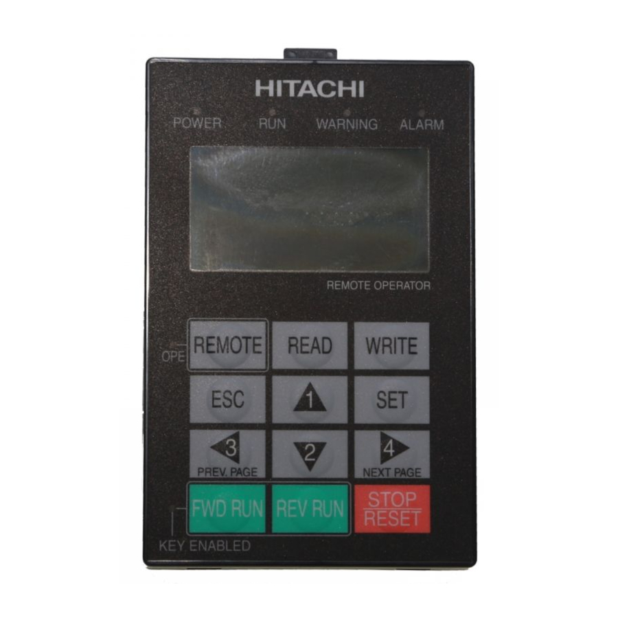
Chapter 2 Name of parts and contents Chapter 2 Name of parts and functions of WOP 2.1 Name of parts and contents 2 RUN LED 9 Connector (RJ45) 3 WARNING LED 4 ALARM LED 1 POWER LED ○ ○ ○ ○... -
Page 8: Operation Keys And Their Functions
Chapter 2 Name of parts and functions of WOP 2.2 Operation keys and their functions ○ ○ ○ ○ REMOTE OPERATOR ○ ○ In the case of connecting to WJ200 (Ver.2.0 or above) or NE-S1, key functions are shown in Tab. -
Page 9: Initialize Inverter
Chapter 2 Name of parts and functions of WOP Key Name Function ·The key is used to move left. ·It moves to the previous mode when the display is navigation layer. ·The key is used to move right. ·It changes display mode from one to another when the display is navigation layer. -
Page 10: Lcd Display
Chapter 2 Name of parts and functions of WOP 2.4 LCD display In the case of connecting to WJ200 (Ver.2.00 or above) or NE-S1, the status and color of LCD backlight and the details of LCD display are described as follow. Backlight When connecting to WJ200 (Ver.2.0 or above) or NE-S1, there are two kinds of backlight colors of LCD display, white and orange, and the state of the inverter is displayed by different... - Page 11 Chapter 2 Name of parts and functions of WOP Tab. 5 The first line of LCD display Item Display character Contents MONITOR-A Monitor mode A MONITOR-B Monitor mode B FUNCTION Function mode Display mode TRIP Trip mode WARNING Warning mode (Alarm) OPTION Option mode The first control object...
-
Page 12: Connect To Sj700,L700,X200 And Wj200 (Before Version 2.0)
Chapter 2 Name of parts and functions of WOP 2.5 Connect to SJ700,L700,X200 and WJ200 (before Version 2.0) Display contents and operation system of WOP are different according to the inverter type that is connected to. When WOP is connected to SJ700, L700, X200 and WJ200 (before Version 2.0), it displays in the same way of former remote operators such as SRW-OJ and SRW-OEX. -
Page 13: Chapter 3 Connection, Wiring, And Attaching
Chapter 3 Connection, wiring, and attaching Chapter 3 Connection, wiring, and attaching Before install the operator on the control panel, please fix with M3 screws from the back of the control panel. (2 holes, the same measurement as figure 4, has to be made at first ) When connecting to the inverter, please use cable which is recommended. -
Page 14: Chapter 4 Operation
Chapter 4 Operation Chapter 4 Operation 4.1 Changing display mode When connecting to WJ200 (Ver.2.0 or above) or NE-S1, WOP has four display modes which can be changed from one to another via pressing the [] or [] key at Navigation level. Moreover, there are 3 other modes: Read mode, Write mode and Option mode. - Page 15 Chapter 4 Operation The outline of each mode is shown as follows. The chosen of parameter b038 decides the power-on display of inverter when connecting to WJ200 (Ver.2.0 or above) or NE-S1. Monitor mode A (Monitor + Setting) On the same screen in this mode, the “d” group inverter MONITOR-A M1-STOP ALL parameters can be displayed , moreover, “F”, “A”, “b”, “C”, “H”,...
-
Page 16: Operation Of Monitor Mode A
Chapter 4 Operation 4.2 Operation of Monitor mode A 1. Please select monitor mode A via pressing the [] or [] MONITOR-A M1-STOP ALL key at navigation layer. The cursor will not appear at this d001 Output FQ layer until pressing the [SET] key. 0.00Hz F001 6.00Hz... -
Page 17: Operation Of Monitor Mode B
Chapter 4 Operation 4.3 Operation of Monitor mode B 1. Please select monitor mode B via pressing the [] or [] MONITOR-B M1-STOP ALL key at navigation layer. The cursor will not appear at this Output FQ 0.00Hz layer until pressing the [SET] key. Output current 0.00A Input... -
Page 18: Operation Of Function Mode
Chapter 4 Operation 4.4 Operation of Function mode 1. Please select function mode via pressing the [] or [] FUNCTION M1-STOP ALL key at navigation level. The cursor will not appear at this F001 layer. Set Frequency(OPE) 6.00Hz [0.00 - 50.00] FUNCTION M1-STOP ALL 2. -
Page 19: Operation Of Trip Mode
Chapter 4 Operation 4.5 Operation of Trip mode 1. Pressing the [] or [] key to select trip mode at TRIP M1-STOP ALL navigation layer. E09.3 UnderVoltage 2. Pressing the [SET] key entries into the below layer.This 10/07/18 11:52 Const. mode will display the past trip information (6 times) and warning information (1 time). -
Page 20: Operation Of Option Mode
Chapter 4 Operation Operation of Option mode 1. Please press the [], [] and [] key at the same time to OPTION MODE OPTION MODE enter into the OPTION MODE. The cursor will appear in 1.Language 1.Language the first row .Pressing the [] or [] key to select the item. 2.Set Clock 2.Date and Time Pressing the [ESC] key it will return to previous display. - Page 21 Chapter 4 Operation Tab. 8 The contents of Option mode Item Content Setting range Default 01: English 02: Deutsch (German) 03: Français (French) 04: Español (Spanish) Setting language. 05: Italiano (Italian) If the language is not installed, it is 06: Portuguës(Portuguese) Language English displayed in English.
- Page 22 Chapter 4 Operation Item Content Setting range Default Resetting all the settings of WOP to the default. 01: YES Operator Reset After reset operation, date and time 02: NO setting is required. 1.Key & Led Check 2.Lcd Check 3.RTC Check Checking whether LED and key etc.
-
Page 23: Chapter 5 Read, Write Function And Operation
Chapter 5 Read, Write function and operation Chapter 5 Read, Write function and operation WOP can read and save Inverter parameter, and copy them to another inverter. WOP can save four inverters’ parameter or one inverter’s parameter and its EzSQ program. It can be selected via changing item of R/W Storage Mode in Option mode. -
Page 24: R/W Storage Mode: Single ・ Read Function
Chapter 5 Read, Write function and operation 5.1 R/W Storage Mode: Single ・ READ function When the R/W Storage Mode is selected to [01: Single], the parameter Read or Write is executed immediately after pressing [READ] or [WRITE] key. It is convenient to write the parameters into numerous inverters (the same type) continuously. -
Page 25: R/W Storage Mode: Single ・ Write Function
Chapter 5 Read, Write function and operation R/W Storage Mode: Single ・ WRITE function After pressing the [WRITE] key in any display mode except Read mode and Option mode, the parameter settings stored in WOP are transferred to the inverter. EzSQ program is transferred to the inverter automatically after parameter copy is finished if the Inverter supports EzSQ function. -
Page 26: R/W Storage Mode: Quad ・ Read Function
Chapter 5 Read, Write function and operation R/W Storage Mode: Quad ・ READ function It is possible to handle four sets of inverter parameters or read/write EzSQ program independently when the item of [R/W storage mode] is selected to [02: Quad]. In this case, WOP can save four sets of inverter parameters or one set of inverter parameters and one EzSQ program. - Page 27 Chapter 5 Read, Write function and operation READ In any display mode except Write mode and Option mode, 1.------ --:-- ----- the read screen is displayed after pressing the [READ] key. If there are no parameters stored in operator, it shows “--”, as 2.------ --:-- ----- described in the right figture.
-
Page 28: R/W Storage Mode: Quad ・ Verify Function
Chapter 5 Read, Write function and operation R/W Storage Mode: Quad ・ VERIFY function In any display mode except Write mode and Option mode, READ the read screen is displayed after pressing the [READ] key. 1.100718 14:50 INV81 Use the [] or [] key to move the cursor up and down to E.------ --:-- ----- select the data number to be verified. -
Page 29: R/W Storage Mode: Quad ・ Write Function
Chapter 5 Read, Write function and operation R/W Storage Mode: Quad ・ WRITE function WRITE In any display mode except READ mode and Option mode, 1.100718 14:50 INV81 the write screen is displayed after pressing the [WRITE] key . E.------ --:-- ----- Use the [] or [] key to move the cursor up and down to select the data number to be written. -
Page 30: Operation Condition Of Read And Write Function
Chapter 5 Read, Write function and operation 5.6 Operation condition of read and write function Please note that the read and write function are invalidated according to the state and the setting of inverter as shown in below table. The operation condition of reading or verifying parameter (WOP INV) ... -
Page 31: Chapter 6 Inverter Setting Concerning Wop
Chapter 6 Inverter setting concerning WOP Chapter 6 Inverter setting concerning WOP The example below explains parameter settings of WJ200 (Ver.2.0 or above) concerning WOP. Tab.9 The parameter of inverter related to WOP Code Function name Content Setting parameter You could set the frequency when Output frequency F001 the frequency instruction is done... -
Page 32: Chapter 7 Error Message
Chapter 7 Error message Chapter 7 Error message Error messages displayed on the screen are classified into errors related to inverter and WOP errors. They appears on the screen as shown below. (For inverter error messages、please refer to the inverter instruction manual) (1) The message related to inverter Display Cause... - Page 33 Chapter 7 Error message (2) WOP error message Display Cause Check item Resetting Method WOP’s EEPROM Check read operation is If the copy function is EEPROM is comes to its usage available when needed, please replace broken! life. inverter is power-on again. the remote operator.
-
Page 34: Chapter 8 Trouble Shooting
Please contact your chapter 3. Hitachi representative. (2) In Option Mode, Read mode or Write mode, [REMOTE] key, [READ] key, [WRITE] key, [FWD RUN] key and [REV RUN] run key are invalid. (3) If the operator screen becomes dark or characters cannot be identified, inductive noise may be entered from the cable. -
Page 35: Chapter 9 Specification
Chapter 9 Specification Chapter 9 Specification 9.1 Specification Tab. 10 WOP’s standard specification Specification Contents Model Display Liquid Crystal Display (132×64 dots) Language Multi- language for WJ200 (Ver.2.0 or above). (NOTE 1) display English for L700, SJ700, X200, NE-S1 and WJ200 (version before 2.0) External 123(H) ×... -
Page 36: Dimensions
Chapter 9 Specification 9.2 Dimensions F i g. 6 D i me nsi on o f W O P... -
Page 37: Battery Exchange
Chapter 9 Specification 9.3 Battery exchange There is a real time clock IC built-in whose power is supplied by a battery when outside power supply is turned off. When the battery comes to its life, the clock IC won’t renew the time when power supply of WOP is turned off.