
Related Manuals for Honeywell AQ25A Series


Summary of Contents for Honeywell AQ25A Series
- Page 1 Hydronics Technical Reference Book Aquatrol Hydronic Boiler Controls 63-9963_Tech_Ref_Cover_5_10.indd 1 5/7/10 11:20:58 AM...
- Page 2 63-9963 Rev. 05-10...
- Page 3 Hydronic Technical Reference Book Contents Aquatrol Hydronic Boiler Controls Form Number Page Control Modules AQ25A Series Programmable Boiler Control Panels Product Data 69-2119-02 AQ250 Series Hydronic Control Panels Product Data 68-0306-02 AQ251 Series Boiler Reset Control Panels Product Data 69-1974-04...
- Page 4 63-9963 Rev. 05-10...
- Page 5 Control Modules Rev. 05-10 63-9963...
- Page 6 63-9963 Rev. 05-10...
-
Page 7: Table Of Contents
AQ25A Series Programmable Boiler Control Panels PRODUCT DATA FEATURES The AQ25A Series Programmable Boiler Control Panels have the following features: • Boiler supply and return temperature sensors • Outdoor temperature sensor • Zoning equipment (zone valves or pumps) • Availability of two Zoning Modules: the AQ15740B, for... -
Page 8: Specifications
If you have additional questions, need further information, or would like to comment on our products or services, please write or phone: 1. Your local Honeywell Automation and Control Products Sales Office (check white pages of your phone directory). 2. Honeywell Customer Care... -
Page 9: Installation Preparation
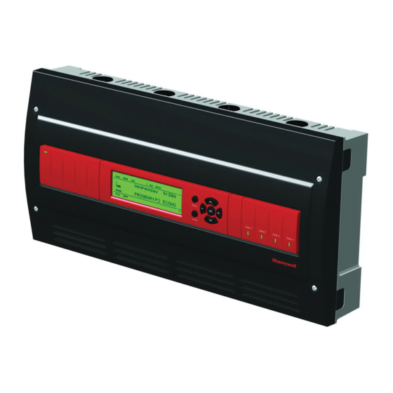
(i.e., AQ25744B) is used; • Zoning equipment (zone valves or pumps) — Control Module refers to the component within an AQ25A Series Control Panel that performs the master Read All Instructions Carefully Before control operations. See Table 1 on page 2 for specific models. - Page 10 VOLTAGE (120 V) FOR THE AQ25A42B TERMINALS CAN BE LINE VOLTAGE (IF USED WITH PUMPS) OR LOW VOLTAGE (IF USED WITH ZONE VALVES) M27753A Fig. 1. AQ25A Series Programmable Boiler Control Panel layout (AQ25A42B shown). CONTACTS SYMBOL Menu Zone 1...
-
Page 11: Mounting
Mount the control panel on the wall: Expansion Zoning Panel, ensuring it is level with the 1. Use the template supplied with the AQ25A Series adjoining Control Panel, and install two lower screws. Programmable Boiler Control Panel to mark mounting 3. - Page 12 AQ25A SERIES PROGRAMMABLE BOILER CONTROL PANELS TO EXPANSION ZONING MODULES (IF INSTALLED) STEP 1 STEP 2 STEP 3 Menu Zone 1 Zone 2 Zone 3 Zone 4 Home STEP 6 STEP 5 STEP 4 M27755A Fig. 4. Wiring sequence. Step 1 – Transformer Wiring Step 2 –...
- Page 13 AQ25A SERIES PROGRAMMABLE BOILER CONTROL PANELS The Boiler Return sensor should be installed on the return piping as close to the entrance port to the boiler as practical, using the other AQ12C11 strap-on sensor supplied with the AQ25A. The correct location is one that will measure the temperature of all combined sources of water returning back to the boiler.
- Page 14 AQ25A SERIES PROGRAMMABLE BOILER CONTROL PANELS minutes of a call for heat and then allows the space heating These contacts are made any time the system has a request needs to be added in for the next 30 minutes. This cycle for boiler operation, unless the water supply temperature is continues until the call for heat is satisfied.
- Page 15 AQ25A SERIES PROGRAMMABLE BOILER CONTROL PANELS Step 3 – Thermostats Wiring Step 4 – Zoning Equipment Wiring Because the Zoning Module of the AQ25A Control Panel can NOTE: The new AQ2000 panels will work with digital (elec- be used with either line voltage pumps or valves, or low voltage tronic) non-communicating thermostats.
- Page 16 AQ10X38 transformer supplied with the AQ25A Control Panel. This integral transformer has enough power to operate 4 motorized zone valves (such as Honeywell V8043E valves or 4 valves using low- amperage draw, heat motor actuators such as FROM LOW VOLTAGE...
- Page 17 AQ25A SERIES PROGRAMMABLE BOILER CONTROL PANELS 100 VA TRANSFORMER 115 VAC 100 VA TRANSFORMER THERMOSTATS THERMOSTATS ZONE 1 ZONE 2 ZONE 3 ZONE 4 ZONE 1 ZONE 2 ZONE 3 ZONE 4 115 VAC 24 VAC USING AN AQ15740B USING AN AQ15540B...
- Page 18 AQ25A SERIES PROGRAMMABLE BOILER CONTROL PANELS Step 5 – Line Voltage System Outputs Refer to Fig. 15 and follow the steps in this section to wire these devices to the AQ25A Control Module. “1. Boiler Pump” “2. DHW Device” “3. Line Voltage Rated Aux Output (Aux. Pump)” on page 13...
- Page 19 AQ25A SERIES PROGRAMMABLE BOILER CONTROL PANELS 3. Line Voltage Rated Aux Output (Aux. Pump) NOTE: Use of this output is optional. The Aux. pump dry contacts are line voltage-rated but unpowered. A low To connect a line voltage auxiliary device to these contacts,...
-
Page 20: Program And Configure The Control Panel
Panel. 4 PROGRAM AND CONFIGURE THE CONTROL PANEL M23731A Only two steps are required to set up the AQ25A Series Control Panel: Fig. 20. Location of Zoning Modules DIP switches. 1. Check the program settings for the Control Module: Operation of the AQ25A's Control Module is set by the... - Page 21 AQ25A SERIES PROGRAMMABLE BOILER CONTROL PANELS When you finish setting the DIP switches for all the Zoning NOTE: The snap-on DIP switch covers are designed so they Modules, replace the front cover of the AQ25A Control Panel cannot be removed (exposing the DIP switches) and the cover of each Expansion Zoning Panel.
- Page 22 AQ25A SERIES PROGRAMMABLE BOILER CONTROL PANELS AQ25A – System Programming and v Press these buttons to scroll up/down in the menu items. Pressing one of these buttons automatically This section describes how to navigate the user interface using saves your current selection, exits the edit mode, the keypad and LCD display, and how to program the AQ25A and moves to the previous or next menu item.
- Page 23 AQ25A SERIES PROGRAMMABLE BOILER CONTROL PANELS LCD Display Navigation NOTES: Home Page display upon restart after a power failure of more than four hours: This section describes how the keypad is used to navigate the Upon restarting the AQ25A following a power dis- LCD display and menus.
-
Page 24: Test And Check Out The Installation
AQ25A SERIES PROGRAMMABLE BOILER CONTROL PANELS Refer to Table 5 on page 24 in the “Appendix” for all of the displayed at the top or bottom of the LCD display (refer to User Menu options for the AQ25A Control Panel, the factory Fig. -
Page 25: Purge Air From All System And Zone Piping
OF ALL SYSTEM SETTINGS c. Depending on the settings for the AUX.PUMP (line After the AQ25A Series Control Panel has been set up, and the voltage rated dry contacts) and the AUX OUT (low entire hydronic installation is operating properly, it is important voltage rated dry contacts), either or both of these to document all the system settings for future reference. -
Page 26: Troubleshooting
AQ25A SERIES PROGRAMMABLE BOILER CONTROL PANELS be copied to the AQ25A’s CURRENT settings and the This diagnostic information is very valuable and the System Control Panel begins to operate with these values Status page is the first place a contractor should look for immediately. - Page 27 AQ25A SERIES PROGRAMMABLE BOILER CONTROL PANELS Single Zone Freeze Protection mode is disabled when the measured by the supply temperature sensor. This target outdoor temperature is above the warm weather shutdown temperature is the reset temp (if the boiler RESET parameter = (WWSD) temperature setting.
- Page 28 AQ25A SERIES PROGRAMMABLE BOILER CONTROL PANELS Table 4. LCD Status Notices and Error Messages. (Continued) LCD Display Parameter Meaning HEATING Boiler is active to serve zones. IDLE Boiler is not active. BOILER: (continued) INIT Boiler contacts (terminals 22-23) on the AQ152A, which are connected to the boiler's T-T terminals, have been shorted and the boiler is beginning its firing sequence.
-
Page 29: Appendix
AQ25A SERIES PROGRAMMABLE BOILER CONTROL PANELS APPENDIX NOTES: PLS SET DAY/TIME displays after a power outage of more than 4 hours. The appendix provides AQ25A Control Panel user interface PROGRAM displays the current active program information for the: (Leave, Return, Sleep, Wake, Occ, or Unocc). - Page 30 AQ25A SERIES PROGRAMMABLE BOILER CONTROL PANELS Table 5. User Menu. Factory Menu Option Range Default Description SYSTEM STATUS Identifies what is happening within the system. See Table 4 on Multiple status and alarm messages can display on this page 21 page.
- Page 31 AQ25A SERIES PROGRAMMABLE BOILER CONTROL PANELS Table 5. User Menu. (Continued) Factory Menu Option Range Default Description ZONE SETTINGS Displays all information pertaining to the selected zone(s). There are four possible sub- menu displays: 1. EDIT ALL ZONES 2. EDIT SINGLE ZONE - Ambient Style (see page 26) 3.
- Page 32 AQ25A SERIES PROGRAMMABLE BOILER CONTROL PANELS Table 5. User Menu. (Continued) Factory Menu Option Range Default Description EDIT SINGLE ZONE Ambient Style — Selecting this menu item displays the following options: ZONE #A-X A-1 to A-16 Each zone on the AQUATROL network has a unique …...
- Page 33 AQ25A SERIES PROGRAMMABLE BOILER CONTROL PANELS Table 5. User Menu. (Continued) Factory Menu Option Range Default Description EDIT SINGLE ZONE Floor Style — Selecting this menu item displays the following options: FLOOR TEMP 32°F to 158°F Display only. This is the temperature measured by the floor (0ºC to 70°C)
- Page 34 AQ25A SERIES PROGRAMMABLE BOILER CONTROL PANELS Table 5. User Menu. (Continued) Factory Menu Option Range Default Description EDIT SINGLE ZONE Ambient/Floor Style (continued) 41°F to 100°F 100°F Maximum floor temperature allowed for a given zone that is FLOOR LIMIT HI (5ºC to 38 °C)
- Page 35 AQ25A SERIES PROGRAMMABLE BOILER CONTROL PANELS Table 5. User Menu. (Continued) Factory Menu Option Range Default Description Displays the summary and zone relay activity (hours of operation or cycles since last STATISTICS reset). LAST DATA RESET Max. 24,855 days 2000 JAN 01 Date of last reset formatted as YYYY MMM DD.
-
Page 36: Installer Menu
AQ25A SERIES PROGRAMMABLE BOILER CONTROL PANELS Installer Menu NOTE: Illustrations of the complete Installer Menu begin on page 38. The Installer Menu allows you to set up and modify system settings that typically would be adjusted by a trained installer. - Page 37 AQ25A SERIES PROGRAMMABLE BOILER CONTROL PANELS Table 6. Installer Menu – Equipment Setup. (Continued) EQUIPMENT SETUP Factory Menu Option Range Default Description BOILER OPERATION CYCLES/HOUR 2 to 6 The number of heating cycles per hour that the control will operate the boiler...
- Page 38 AQ25A SERIES PROGRAMMABLE BOILER CONTROL PANELS Table 6. Installer Menu – Equipment Setup. (Continued) EQUIPMENT SETUP Factory Menu Option Range Default Description DOMEST.HOT WATER (continued) DHW PURGE YES / NO Displays only if DHW = ENABLE. Selects whether or not a purge should be applied after a DHW demand has been served.
- Page 39 AQ25A SERIES PROGRAMMABLE BOILER CONTROL PANELS Table 6. Installer Menu – Equipment Setup. (Continued) EQUIPMENT SETUP Factory Menu Option Range Default Description Settings which the AQ25A uses to control the system based on input to the AUX. IN terminals or AUXILIARY I/O to control the activation of the AUX.OUT and AUX.PUMP outputs.
- Page 40 AQ25A SERIES PROGRAMMABLE BOILER CONTROL PANELS Table 6. Installer Menu – Equipment Setup. (Continued) EQUIPMENT SETUP Factory Menu Option Range Default Description A/C EQUIP CONFIG Central A/C – Available only if no AQ158 controller is present on the network. ZONE A-1 to D-16 Selects the desired zone.
- Page 41 AQ25A SERIES PROGRAMMABLE BOILER CONTROL PANELS Table 7. Installer Menu – Test and Purge. TEST and PURGE Factory Menu Option Range Default Description TEST OUTPUTS Tests the individual system outputs to ensure correct operation. BOILER PUMP ON / OFF Energizes / de-energizes the line voltage terminals marked Boiler when switched to ON / OFF respectively.
- Page 42 AQ25A SERIES PROGRAMMABLE BOILER CONTROL PANELS Table 7. Installer Menu – Test and Purge. (Continued) TEST and PURGE Factory Menu Option Range Default Description TEST ZONES Tests the zone equipment individually, or sequentially, to ensure correct operation ALL ZONES Sequentially energizes / de-energizes all zones connected to the AQUATROL network.
- Page 43 AQ25A SERIES PROGRAMMABLE BOILER CONTROL PANELS Menu Structure User Menu Structure Press the Menu button on the keypad to display the User This section illustrates the complete menu structure for: Menu. Fig. 24 illustrates all possible User Menu selections. • User Menu •...
- Page 44 AQ25A SERIES PROGRAMMABLE BOILER CONTROL PANELS Installer Menu Structure To display the Installer Menu, go to the Home Page, press and hold the OK button for 3 seconds until the message INSTALLER MODE – ARE YOU SURE? displays. Select YES and press the OK button. Fig. 25 and Fig. 26 on page 39 illustrate all possible Installer Menu selections.
- Page 45 AQ25A SERIES PROGRAMMABLE BOILER CONTROL PANELS INSTALLER MODE INSTALLER MODE ARE YOU SURE? INSTALLER MENU EQUIPMENT SETUP TEST AND PURGE TEST AND PURGE EXIT INSTALLER TEST OUTPUTS TEST OUTPUTS TEST SENSORS BOILER PUMP: TEST ZONES AUX. PUMP: PURGE DHW PUMP:...
- Page 46 AQ25A SERIES PROGRAMMABLE BOILER CONTROL PANELS AQUATROL® is a registered trademark of Honeywell International Inc. Aquastat® is a registered trademark of Honeywell International Inc. Automation and Control Solutions Honeywell International Inc. Honeywell Limited-Honeywell Limitée 1985 Douglas Drive North 35 Dynamic Drive...
- Page 47 AQ250 Series Hydronic Control Panels PRODUCT DATA FEATURES Need new photo of AQ250 The AQ250 Series Hydronic Control Panels have the following features: • Zoning Control for up to four, single-stage zones or two, two-stage zones as shipped; can be expanded to a total of 16 zones with AQ255 or AQ257 expansion zoning panels, and up to 64 zones by using up to three AQ254 Add-a-Temperature expansion panels and...
-
Page 48: Specifications
If you have additional questions, need further information, or would like to comment on our products or services, please write or phone: 1. Your local Honeywell Automation and Control Products Sales Office (check white pages of your phone directory). 2. Honeywell Customer Care... -
Page 49: Installation Preparation
Refer to Fig. 1 on page 4. All AQ250 Control Panels consist of panel enclosure. Zoning Modules are available in either three functional components: 4-zone or 8-zone configurations. Refer to Honeywell 1. AQ10X38 transformer (power supply module), which literature Form No. 69-1981 for more information on connects to 120 Vac power and supplies 24 Vac power to these products. -
Page 50: Mounting
AQ250 SERIES HYDRONIC CONTROL PANELS In general, the top terminals of the AQ2000 Series components For these the two exceptions, the bottom terminals of the carry low voltage (24 Vac) power and the bottom terminals Transformer and Control Module carry line voltage (120 Vac), carry line voltage (120 Vac) power. -
Page 51: Wiring Procedure
• “Step 3 – Thermostats Wiring” on page 8 ment. For additional information, refer to • “Step 4 – Zoning Equipment Wiring” on page 8 http:// customer.honeywell.com or your local distribu- • “Step 5 – Line Voltage System Outputs” on page 10 tor. - Page 52 AQ250 SERIES HYDRONIC CONTROL PANELS TO EXPANSION ZONING MODULES (IF INSTALLED) STEP 1 STEP 2 STEP 3 Boiler Aux. Boiler STEP 6 STEP 5 STEP 4 M29034A Fig. 4. Wiring sequence. Step 1 – Transformer Wiring Temperature Sensor Wiring Connect the lead wires of each sensor to the corresponding Factory pre-wiring of the Control Panels is shown as dotted terminals on top of the AQ15000B Control Module.
- Page 53 If Communication Bus Wiring shielded cable is used, Honeywell recommends the All AQ2000 components communicate with each other on the use of shielded cable with a continuous ground plane, AQUATROL network using communication bus wiring.
- Page 54 AQ250 SERIES HYDRONIC CONTROL PANELS Step 3 – Thermostats Wiring Step 4 – Zoning Equipment Wiring Because the Zoning Module of the AQ25042B Control Panel NOTE: The new AQ2000 panels will work with either digital can be used with either line voltage pumps or valves, or low (electronic) non-communicating thermostats or voltage zone valves (with or without end switches), field AQ1000 communicating thermostats.
- Page 55 Control Panel. This integral transformer has enough field wiring is required. power to operate 4 motorized zone valves (such as Honeywell V8043E valves or 4 valves using low- amperage draw, heat motor actuators, such as Honeywell MV100 actuators), plus power the electronics of the AQ250's Control Module and up to 16 AQ1000 thermostats.
- Page 56 AQ250 SERIES HYDRONIC CONTROL PANELS 100 VA TRANSFORMER 115 VAC 100 VA TRANSFORMER THERMOSTATS THERMOSTATS ZONE 1 ZONE 2 ZONE 3 ZONE 4 ZONE 1 ZONE 2 ZONE 3 ZONE 4 115 VAC 24 VAC USING AN AQ15740B USING AN AQ15540B VALVE ZONING MODULE PUMP ZONING MODULE Zone 1...
- Page 57 AQ250 SERIES HYDRONIC CONTROL PANELS TO BOILER TERMINALS 11-12 ON TOP OF AQ15200B CONTROL MODULE L8124, L7224 JUMPERED AT FACTORY FROM LINE TO AUXILIARY DEVICE VOLTAGE 120V (INSTALLER-DEFINED) TERMINALS (N AND L) ON BOTTOM OF TRANSFORMER BOILER (HOT) PUMP R8184 C554 BLACK ORANGE...
- Page 58 AQ250 SERIES HYDRONIC CONTROL PANELS 1. Boiler Pump NOTE: If the AQ250 is connected to a modulating condensing boiler, the DHW pump will probably need Connect the N and L wires of the boiler loop pump to the N and to be connected to the boiler, not the AQ250.
- Page 59 AQ250 SERIES HYDRONIC CONTROL PANELS Step 6 – Connection To Line Voltage Power CAUTION Connect the N and L line voltage inputs of the primary on the AQ250 transformer to the electrical distribution panel and Electrical Shock or Equipment Damage Hazard. power up the Control.
-
Page 60: Configure The Control Panel Dip Switches
Control Module and the Zoning Module(s) are suitable, AQ250 Control Module DIP Switch Location Honeywell recommends that they be reviewed, and changed as necessary, to get optimal performance of the hydronic Operation of the AQ250’s Control Module is set by the system controlled by the AQ2000 Series products. - Page 61 AQ250 SERIES HYDRONIC CONTROL PANELS Table 2. AQ15000B Control Module DIP switch arrangement DIP Switch Switch Description Label and Factory Settings AQ15000B Diagnostic Diagnostic Test Test DHW Device: Pump or Valve DHW Priority: Off or Priority DHW Priority Override: Off or O/Ride (override) Boiler post purge location: Off = zones only;...
- Page 62 AQ250 SERIES HYDRONIC CONTROL PANELS Table 3. AQ15540B Zoning Module (Pump Zoning Module) DIP Switch Arrangement. Switch Switch Description Label and Factory Settings Zone Address: The positions of these 4 DIP switches define the unique address for each zone on the AQUATROL network. For each group of 4 zones, there can be only one DIP switch in the right hand (On) position.
-
Page 63: Test And Check Out The Installation
AQ250 SERIES HYDRONIC CONTROL PANELS 5 TEST AND CHECK OUT THE 5. Pressing the Test button at any time during the Auto Test routine pauses the routine indefinitely. While paused, the INSTALLATION Diagnostic LED blinks slowly. 6. Pressing the Test button while the Auto Test routine is paused advances the routine to the start of the next step Startup in the routine (testing the next output) and the Auto Test... - Page 64 AQ250 SERIES HYDRONIC CONTROL PANELS Checkout 4. Pressing the Test button at any time during the Auto Test routine pauses the routine indefinitely. While paused, the 1. If present, turn down the DHW Aquastat to avoid interfer- Diagnostic LED blinks slowly. ing with space heating control operation.
-
Page 65: Purge Air From All System And Zone Piping
AQ250 SERIES HYDRONIC CONTROL PANELS 6 PURGE AIR FROM ALL SYSTEM TROUBLESHOOTING AND ZONE PIPING The following information helps the installer correctly identify system problems, making troubleshooting much faster. Table 4 Purging air from all zones in the hydronic system is easily and Table 5 on page 20 describe the possible error codes that accomplished with the AQ250 by using a modification to the can be communicated on the diagnostic LEDs of the... - Page 66 Communication lost with ALL Check thermostat wiring to Zoning pause thermostats Modules. AQUATROL® is a registered trademark of Honeywell International Inc. Aquastat® is a registered trademark of Honeywell International Inc. Automation and Control Solutions Honeywell International Inc. Honeywell Limited-Honeywell Limitée...
- Page 67 AQ251 Series Boiler Reset Control Panels PRODUCT DATA FEATURES The AQ251 Series has the following features: • Outdoor temperature compensation (reset), or Load reset based on indoor temperature feedback, or none • Domestic hot water (DHW) priority and priority override protection. •...
-
Page 68: Specifications
If you have additional questions, need further information, or would like to comment on our products or services, please write or phone: 1. Your local Honeywell Automation and Control Products Sales Office (check white pages of your phone directory). 2. Honeywell Customer Care... -
Page 69: Installation Preparation
AQ251 SERIES BOILER RESET CONTROL PANELS Mixing Valve Output (floating, open/close) (dry relay): Thermostat Compatibility: Digital thermostats and/or AQ1000 Series 2-wire communicating thermostats 24 Vac, 12 VA Supply/Return Loop Sensor: 10K ohm NTC thermistor at Interface and Timings: 77°F (25°C) ± 0.5°F (±0.3°C). Lead length: 10 ft. (3.0 m); up User Interface (Setting, Programming): LCD Display to 500 ft. - Page 70 AQ251 SERIES BOILER RESET CONTROL PANELS Familiarize Yourself With the AQ251 Control AQ251 Control Panels can control a maximum of 16 zones by connecting additional Expansion Zoning Panels to the AQ251 Panel Layout Control Panel. Each Expansion Zoning Panel is configured with its own bank of DIP switches, located in the left-most Refer to Fig.
-
Page 71: Mounting
Several wiring diagrams are included in this document. For additional information, refer to If not done already, run low voltage thermostat wire (24 gauge http:// customer.honeywell.com or your local or heavier) from the thermostats back to the Zoning Modules distributor. -
Page 72: Wiring Procedure
AQ251 SERIES BOILER RESET CONTROL PANELS 3 WIRING PROCEDURE Beginning with the top left of Fig. 4 and moving clockwise around the panel, wire components to the AQ251 Control The AQ251 Control Panel is pre-wired at the factory, making Panel and Expansion Zoning Panels (if installed) in the for faster installation: following six steps: •... - Page 73 AQ251 panel. Do not ground the shield or conduit at any other location or electromagnetic shielding will be ineffective. If shielded cable is used, Honeywell recommends the use of shielded cable with a continuous ground plane, such as foil, with an integral drain wire for bonding to earth ground.
- Page 74 AQ251 SERIES BOILER RESET CONTROL PANELS DOMESTIC HOT WATER These contacts are made any time the system has a request for boiler operation, unless the water supply temperature is Wire the DHW (terminals 13 and 14) to the Aquastat or above the target temp at that time, at which time the system thermostat on the domestic hot water tank.
- Page 75 AQ251 SERIES BOILER RESET CONTROL PANELS Step 3 – Thermostats Wiring Step 4 – Zoning Equipment Wiring Because the Zoning Module of the AQ25142B Control Panel NOTE: The new AQ2000 panels will work with either digital can be used with either low voltage zone valves (without end (electronic) non-communicating thermostats or switches) or line voltage pumps or valves, field installed wiring AQ1000 communicating thermostats.
- Page 76 AQ10X38 transformer supplied with the AQ251 Control Panel. This integral transformer has enough power to operate 4 motorized zone valves (such as Honeywell V8043E valves or 4 valves using low- amperage draw, heat motor actuators, such as FROM LOW VOLTAGE...
- Page 77 AQ251 SERIES BOILER RESET CONTROL PANELS 100 VA TRANSFORMER 115 VAC 100 VA TRANSFORMER THERMOSTATS THERMOSTATS ZONE 1 ZONE 2 ZONE 3 ZONE 4 ZONE 1 ZONE 2 ZONE 3 ZONE 4 115 VAC 24 VAC USING AN AQ15740B USING AN AQ15540B VALVE ZONING MODULE PUMP ZONING MODULE Zone 1...
- Page 78 AQ251 SERIES BOILER RESET CONTROL PANELS Step 5 – Line Voltage System Outputs Refer to Fig. 15 and follow the steps in this section to wire these devices to the AQ251 Control Module. “1. Boiler Pump” “2. DHW Device” “3. Line Voltage Rated Aux Output (Aux. pump)” on page 13 FROM LINE VOLTAGE 120V TERMINALS (N AND L) ON TO AUXILIARY DEVICE...
- Page 79 AQ251 SERIES BOILER RESET CONTROL PANELS 3. Line Voltage Rated Aux Output (Aux. pump) NOTE: Use of this output is optional. The Aux. pump dry contacts are line voltage-rated but unpowered. A low To connect a line voltage auxiliary device to these contacts, voltage device can be connected to these such as a boiler bypass pump, power the pump from the N and programmable contacts, but the wire's insulation must...
-
Page 80: Program And Configure The Control Panel
Zoning Module are suitable for many installations, Panel and the front cover of the Panel is removed, Honeywell recommends that they be reviewed, and changed there is a risk of electrocution. Be careful to avoid as necessary, to get optimal performance of the hydronic contact with the line voltage (N and L) terminals, either system controlled by the AQ2000 Series products. - Page 81 AQ251 SERIES BOILER RESET CONTROL PANELS Zoning Module DIP Switch Settings 3. DIP Switch 8 functionality: • The factory setting enables 1-stage per zone A chart of the different settings for each DIP switch is attached thermostat. The zoning module operates as four 1- to the inside of each DIP switch cover.
- Page 82 AQ251 SERIES BOILER RESET CONTROL PANELS AQ251 – System Programming and v Press these buttons to scroll up/down in the menu items. Pressing one of these buttons automatically This section describes how to navigate the user interface using saves your current selection, exits the edit mode, the keypad and LCD display, and how to program the AQ251 and moves to the previous or next menu item.
- Page 83 AQ251 SERIES BOILER RESET CONTROL PANELS • If the active menu item requires you to define a value (e.g., Until the DAY and TIME OF DAY settings are a setpoint), use the – or + button to decrease or increase adjusted, the control remains in permanent the value until the desired value is displayed.
-
Page 84: Test And Check Out The Installation
AQ251 SERIES BOILER RESET CONTROL PANELS Test Sensors TO ACCESS THE INSTALLER MENU: 1. Press the Home button to return to the Home Page When TEST SENSORS is selected, the AQ251 LCD displays display. the temperature that each of the SUPPLY, RETURN, SECONDARY and OUTDOOR sensors is measuring. -
Page 85: Purge Air From All System And Zone Piping
AQ251 SERIES BOILER RESET CONTROL PANELS c. Depending on the settings for the AUX.PUMP (line 7. Turn down the DHW Aquastat to end the call for hot voltage-rated dry contacts) and the AUX OUT (low water. Space heating operation should continue (if DHW voltage-rated dry contacts), either or both of these priority is disabled) or resume (if DHW PRIOrity is relays may also close. -
Page 86: Document And Keep A Record Of All System Settings
AQ251 SERIES BOILER RESET CONTROL PANELS 7 DOCUMENT AND KEEP A RECORD • SETUP settings are the specific settings for this installation which an installer has saved after the AQ251 is set up and OF ALL SYSTEM SETTINGS operating well. These are saved for future recall, in case the system’s settings are inadvertently changed. - Page 87 AQ251 SERIES BOILER RESET CONTROL PANELS Communications Loss Single Zone Freeze Protection mode is disabled when the outdoor temperature is above the warm weather shutdown Because all AQ2000 Series components communicate with (WWSD) temperature setting. each other via the dedicated AQUATROL network when controlling a hydronic system, one possible failure mode of the The AQ251 provides Zoning Module diagnostic information via AQ251 would be loss of communication between the AQ1510...
- Page 88 AQ251 SERIES BOILER RESET CONTROL PANELS Table 3. AQ155 / AQ157 Zoning Module LED Display and System Condition. DIAGNOSTIC LED Status System Condition Action Required Steady (no blinking) No system problem detected None Fast blinking (4 blinks per second) Auto Test is in operation None.
-
Page 89: Appendix
AQ251 SERIES BOILER RESET CONTROL PANELS APPENDIX NOTES: PLS SET DAY/TIME displays after a power outage of more than 4 hours. The appendix provides AQ251 Control Panel user interface PROGRAM displays the current active program information for the: (Leave, Return, Sleep, Wake, Occ, or Unocc). —... - Page 90 AQ251 SERIES BOILER RESET CONTROL PANELS Table 5. User Menu. Factory Menu Option Range Default Description SYSTEM STATUS Identifies what is happening within the system. See Table 4 on Multiple status and alarm messages can display on this page 22 page.
- Page 91 AQ251 SERIES BOILER RESET CONTROL PANELS Table 5. User Menu. (Continued) Factory Menu Option Range Default Description ZONE SETTINGS Displays all information pertaining to the selected zone(s). There are four possible sub- menu displays (available only with AQ1000 thermostats): 1. EDIT ALL ZONES 2.
- Page 92 AQ251 SERIES BOILER RESET CONTROL PANELS Table 5. User Menu. (Continued) Factory Menu Option Range Default Description Ambient Style — Selecting this menu item displays the following options: EDIT SINGLE ZONE ZONE #A-X A-1 to A-16 Each zone on the AQUATROL network has a unique …...
- Page 93 AQ251 SERIES BOILER RESET CONTROL PANELS Table 5. User Menu. (Continued) Factory Menu Option Range Default Description Floor Style — Selecting this menu item displays the following options: EDIT SINGLE ZONE FLOOR TEMP 32°F to 158°F Display only. This is the temperature measured by the floor (0ºC to 70°C) temperature sensor.
- Page 94 AQ251 SERIES BOILER RESET CONTROL PANELS Table 5. User Menu. (Continued) Factory Menu Option Range Default Description EDIT SINGLE ZONE Ambient/Floor Style (continued) 41°F to 100°F 100°F Maximum floor temperature allowed for a given zone that is FLOOR LIMIT HI (5ºC to 38 °C) (38°C) controlled by a floor / slab sensor connected to that zone's...
- Page 95 AQ251 SERIES BOILER RESET CONTROL PANELS Table 5. User Menu. (Continued) Factory Menu Option Range Default Description Displays the summary and zone relay activity (hours of operation or cycles since last STATISTICS reset). LAST DATA RESET Max. 24,855 days 2000 JAN 01 Date of last reset formatted as YYYY MMM DD.
-
Page 96: Installer Menu
AQ251 SERIES BOILER RESET CONTROL PANELS Installer Menu NOTE: Illustrations of the complete Installer Menu begin on page 39. The Installer Menu allows you to set up and modify system settings that typically would be adjusted by a trained installer. To access the Installer Menu: These include equipment settings (for boiler operation, DHW 1. - Page 97 AQ251 SERIES BOILER RESET CONTROL PANELS Table 6. Installer Menu – Equipment Setup. (Continued) EQUIPMENT SETUP Factory Menu Option Range Default Description BOILER SETTINGS (continued) OUTDOOR -60°F to 32°F (-51°C to 0°C) 10 °F The lowest annual outdoor temperature for the location (-12°C) where the system is installed, also referred to as the Design Temperature.
- Page 98 • YES = On = Allow DHW Priority override. • NO = Off = Do not allow DHW Priority override. If DHW Priority is selected, Honeywell strongly recommends setting the DHW PRIOR.OVER to YES. DHW DEVICE...
- Page 99 AQ251 SERIES BOILER RESET CONTROL PANELS Table 6. Installer Menu – Equipment Setup. (Continued) EQUIPMENT SETUP Factory Menu Option Range Default Description PRIO.OVER YES / NO Displays only if HT DMND PRIO = YES. Selects whether (following a 30 minute uninterrupted call for Heat Demand) the priority given to the Heat Demand can be overridden to minimize the chance of freeze up or excessive cool down of the space heating zones.
- Page 100 AQ251 SERIES BOILER RESET CONTROL PANELS Table 6. Installer Menu – Equipment Setup. (Continued) EQUIPMENT SETUP Factory Menu Option Range Default Description Central A/C – Available only if no AQ158 controller is present on the network. A/C SETTINGS 2 / 3 / 4 / 5 / 6 The maximum number of times the controller will permit CYCLES/HOUR the central A/C to cycle in each hour.
- Page 101 AQ251 SERIES BOILER RESET CONTROL PANELS Table 6. Installer Menu – Equipment Setup. (Continued) EQUIPMENT SETUP Factory Menu Option Range Default Description SAVE / RESTORE Options for saving settings or restoring previously-saved settings RESTORE Selecting this option restores all settings to their factory FACTORY defaults RESTORE...
- Page 102 AQ251 SERIES BOILER RESET CONTROL PANELS Table 7. Installer Menu – Test and Purge. TEST and PURGE Factory Menu Option Range Default Description TEST OUTPUTS Tests the individual system outputs to ensure correct operation. BOILER PUMP ON / OFF Energizes / de-energizes the line voltage terminals marked Boiler when switched to ON / OFF respectively.
- Page 103 AQ251 SERIES BOILER RESET CONTROL PANELS Table 7. Installer Menu – Test and Purge. (Continued) TEST and PURGE Factory Menu Option Range Default Description TEST ZONES Tests the zone equipment individually, or sequentially, to ensure correct operation ALL ZONES Sequentially energizes / de-energizes all zones connected to the AQUATROL network.
- Page 104 AQ251 SERIES BOILER RESET CONTROL PANELS Menu Structure User Menu Structure Press the Menu button on the keypad to display the User This section illustrates the complete menu structure for: Menu. Fig. 24 illustrates all possible User Menu selections. • User Menu •...
- Page 105 AQ251 SERIES BOILER RESET CONTROL PANELS Installer Menu Structure To display the Installer Menu, go to the Home Page, press and hold the OK button for 3 seconds until the message INSTALLER MODE – ARE YOU SURE? displays. Select YES and press the OK button. Fig. 25 and Fig. 26 illustrate all possible Installer Menu selections. INSTALLER MODE INSTALLER MODE ARE YOU SURE?
- Page 106 THE FACTORY DEFAULT VALUES ARE SHOWN. M27752 Fig. 26. Installer Menu Structure. – Test and Purge. AQUATROL® is a registered trademark of Honeywell International Inc. Aquastat® is a registered trademark of Honeywell International Inc. Automation and Control Solutions Honeywell International Inc.
- Page 107 AQ252 Universal Injection/Mixing Boiler Reset Control Panels PRODUCT DATA FEATURES The AQ252 family have the following features: • Controls one boiler loop and one mixed temperature loop. • Outdoor temperature compensation (reset), or Load reset based on indoor temperature feedback, or none. •...
- Page 108 If you have additional questions, need further information, or would like to comment on our products or services, please write or phone: 1. Your local Honeywell Automation and Control Products Sales Office (check white pages of your phone directory). 2. Honeywell Customer Care...
-
Page 109: Installation Preparation
AQ252 Universal Injection/Mixing Boiler Reset Control Panels Temperature Ratings: Modulating Output: )-10 or 2-10 Vdc for variable speed pump or modulating boiler Boiler Design Temperature: 80°F to 210°F (26°C to 99°C) Mixing Valve (Com, O, C): 324 Vac, 0.5A, 12VA Boiler Differential: 2°F to 41°F (1°C to 23°C), or Auto R–C Input (on Control and Zoning Modules): 24 Vac Class II... - Page 110 AQ252 Universal Injection/Mixing Boiler Reset Control Panels One of two different 4-zone Zoning Modules: WARNING • AQ15740B (part of the AQ25244B Control Panel) for zoning with 24 Vac zone valves with end Risk of electrical shock. switches. Can cause severe injury, property damage or death. •...
-
Page 111: Mounting
AQ252 Universal Injection/Mixing Boiler Reset Control Panels TRANSFORMER CONTROL MODULE ZONING MODULE VOLTAGE (24 V) Zone 1 Zone 2 Zone 3 Zone 4 LINE VOLTAGE (120 V) FOR THE AQ25242B TERMINALS CAN BE LINE VOLTAGE (IF USED WITH PUMPS) OR LOW VOLTAGE (IF USED WITH ZONE VALVES) M27682A Fig. - Page 112 AQ252 Universal Injection/Mixing Boiler Reset Control Panels WIRE CHANNEL PLUGS WIRE CHANNEL PLUGS M23733A Fig. 3. Orientation of wire channel plugs for creating pass-through wire channel and for joining Control Panel to Expansion Zoning Panels. 69-1986—02...
-
Page 113: Wiring Procedure
• “Step 4 – Zoning Equipment Wiring” on page 11 document. For additional information, refer to • “Step 5 – Line Voltage System Outputs” on page 13 http:// customer.honeywell.com or your local • “Step 6 – Connection To Line Voltage Power” on page 14 distributor. - Page 114 AQ252 Universal Injection/Mixing Boiler Reset Control Panels M27685A Fig. 5. Low voltage wiring for the AQ15200B Control Module. Temperature Sensor Wiring SECONDARY (MIXED) LOOP SUPPLY SENSOR The secondary sensor should be installed on the secondary Connect the lead wires of each sensor to the corresponding (mixed) water piping, far enough downstream of the mixing terminals on top of the AQ1520 Control Module.
- Page 115 If Secondary Loop Control: If a 0-10V or 2-10V driven shielded cable is used, Honeywell recommends the variable speed injection pump or a modulating mixing use of shielded cable with a continuous ground plane,...
- Page 116 AQ252 Universal Injection/Mixing Boiler Reset Control Panels Communication Bus Wiring AUX-OUT If the Auxiliary Out low voltage output will be used, wire it now All AQ2000 components communicate with each other on the to the device (e.g., A/C compressor) that will be switched when AQUATROL network using communication bus wiring.
- Page 117 AQ252’s transformer, through the wiring channel across Control Panel. This integral transformer has enough power to operate 4 motorized zone valves (such as Honeywell V8043E valves or 4 valves using low- amperage draw, heat motor actuators, such as Honeywell MV100 actuators), plus power the electronics of the AQ252's Control Module and up to 69-1986—02...
- Page 118 AQ252 Universal Injection/Mixing Boiler Reset Control Panels 16 AQ1000 thermostats. If zone valves with high- CAUTION amperage draw heat-motor actuators are used (such as Taco 500 series zone valves), additional 24 Vac Equipment Damage Hazard. transformer capacity will need to be wired to the Can damage internal circuitry of Zoning Module.
- Page 119 AQ252 Universal Injection/Mixing Boiler Reset Control Panels Step 5 – Line Voltage System Outputs “1. Boiler Pump” “2. DHW Device” Refer to Fig. 15 and follow these steps to wire the devices to “3. Line Voltage Rated Variable Injection Pump” the AQ252 Control Module.
- Page 120 AQ252 Universal Injection/Mixing Boiler Reset Control Panels Setup is enabled in the EQUIPMENT SETUP > SECONDARY NOTE: Use of this output is optional. The Aux. pump dry con- LOOP sub-menu when the INJECT parameter is set to tacts are line voltage-rated but unpowered. A low volt- ENABLE (see Fig.
-
Page 121: Program And Configure The Control Panel
Unpredictable zone behavior may occur if more than and each Zoning Module are suitable for many installations, one Zoning Module has DIP switches (1-4) set to Honeywell recommends that they be reviewed, and changed the same address. as necessary, to get optimal performance of the hydronic 2. - Page 122 AQ252 Universal Injection/Mixing Boiler Reset Control Panels valves. The valve logic induces a delay before • When using digital 2-stage thermostats (non activating the boiler pump even when zone pumps AQ1000 thermostats), the system set-up process are used. When Zone Synchronization is not changes slightly.
- Page 123 AQ252 Universal Injection/Mixing Boiler Reset Control Panels AQ252 – System Programming and v Press these buttons to scroll up/down in the menu items. Pressing one of these buttons automatically This section describes how to navigate the user interface using saves your current selection, exits the edit mode, the keypad and LCD display, and how to program the AQ252 and moves to the previous or next menu item.
- Page 124 AQ252 Universal Injection/Mixing Boiler Reset Control Panels LCD Display Navigation NOTES: Home Page display upon restart after a power failure of more than four hours: This section describes how the keypad is used to navigate the Upon restarting the AQ252 following a power dis- LCD display and menus.
-
Page 125: Test And Check Out The Installation
AQ252 Universal Injection/Mixing Boiler Reset Control Panels Refer to Table 5 on page 25 in the “Appendix” for all of the displayed at the top or bottom of the LCD display (refer to User Menu options for the AQ252 Control Panel, the factory Fig. -
Page 126: Purge Air From All System And Zone Piping
AQ252 Universal Injection/Mixing Boiler Reset Control Panels 3. Turn up the setpoint of one of the thermostats associated After you have defined which loops to purge (all loops, or an with the Boiler (Primary) loop. individual loop) and for how long (using the AQ252’s menus), position the indicator arrow (←) beside the START PURGE a. -
Page 127: Troubleshooting
AQ252 Universal Injection/Mixing Boiler Reset Control Panels • FACTORY settings are the default values loaded at the When an AQ1000 thermostat is disconnected from the factory and are the starting point for programming the AQUATROL network, a message displays on the System AQ252. - Page 128 AQ252 Universal Injection/Mixing Boiler Reset Control Panels wall while a room is being painted. When used with 2-stage The AQ252 provides Zoning Module diagnostic information via thermostat operation, only the first stage will be activated in the the DIAGNOSTIC LEDs located above the DIP switches on its freeze protection mode.
- Page 129 AQ252 Universal Injection/Mixing Boiler Reset Control Panels Table 4. LCD Status Notices and Error Messages. (Continued) LCD Display Parameter Meaning FRZ PROT Boiler freeze protection activated: • Communication between Control Module and Zoning Module has been lost for more than 1 minute •...
-
Page 130: Appendix
AQ252 Universal Injection/Mixing Boiler Reset Control Panels APPENDIX Press the Home button on the keypad to display the Home Page. The appendix provides AQ252 Control Panel user interface NOTES: information for the: PLS SET DAY/TIME displays after a power outage —... - Page 131 AQ252 Universal Injection/Mixing Boiler Reset Control Panels Table 5. User Menu. Factory Menu Option Range Default Description SYSTEM STATUS Identifies what is happening within the system. See Table 4 on Multiple status and alarm messages can display on this page 22 page.
- Page 132 AQ252 Universal Injection/Mixing Boiler Reset Control Panels Table 5. User Menu. (Continued) Factory Menu Option Range Default Description ZONE SETTINGS Displays all information pertaining to the selected zone(s). There are four possible sub- menu displays (available only with AQ1000 thermostats): 1.
- Page 133 AQ252 Universal Injection/Mixing Boiler Reset Control Panels Table 5. User Menu. (Continued) Factory Menu Option Range Default Description Ambient Style — Selecting this menu item displays the following options: EDIT SINGLE ZONE ZONE #A-X A-1 to A-16 Each zone on the AQUATROL network has a unique …...
- Page 134 AQ252 Universal Injection/Mixing Boiler Reset Control Panels Table 5. User Menu. (Continued) Factory Menu Option Range Default Description Floor Style — Selecting this menu item displays the following options: EDIT SINGLE ZONE FLOOR TEMP 32°F to 158°F Display only. This is the temperature measured by the floor (0ºC to 70°C) temperature sensor.
- Page 135 AQ252 Universal Injection/Mixing Boiler Reset Control Panels Table 5. User Menu. (Continued) Factory Menu Option Range Default Description EDIT SINGLE ZONE Ambient/Floor Style (continued) 41°F to 100°F 100°F Maximum floor temperature allowed for a given zone that is FLOOR LIMIT HI (5ºC to 38 °C) (38°C) controlled by a floor / slab sensor connected to that zone's...
- Page 136 AQ252 Universal Injection/Mixing Boiler Reset Control Panels Table 5. User Menu. (Continued) Factory Menu Option Range Default Description Displays the summary and zone relay activity (hours of operation or cycles since last STATISTICS reset). LAST DATA RESET Max. 24,855 days 2000 JAN 01 Date of last reset formatted as YYYY MMM DD.
- Page 137 AQ252 Universal Injection/Mixing Boiler Reset Control Panels Installer Menu NOTE: Illustrations of the complete Installer Menu begin on page 41. The Installer Menu allows you to set up and modify system settings that typically would be adjusted by a trained installer. To access the Installer Menu: These include equipment settings (for boiler operation, DHW 1.
- Page 138 AQ252 Universal Injection/Mixing Boiler Reset Control Panels Table 6. Installer Menu – Equipment Setup. EQUIPMENT SETUP Factory Menu Option Range Default Description Installer-defined settings for the system design parameters (e.g., boiler supply and return BOILER SETTINGS temperatures, reset mode, and outdoor low temperature) HIGH LIMIT 120°F to 225°F (49°C to 190°F...
- Page 139 AQ252 Universal Injection/Mixing Boiler Reset Control Panels Table 6. Installer Menu – Equipment Setup. (Continued) EQUIPMENT SETUP Factory Menu Option Range Default Description BOILER OPERATION CYCLES/HOUR 2 to 6 The number of heating cycles per hour that the control will operate the boiler.
- Page 140 • YES = On = Allow DHW Priority override. • NO = Off = Do not allow DHW Priority override. If DHW Priority is selected, Honeywell strongly recommends setting the DHW PRIOR.OVER to YES. DHW DEVICE...
- Page 141 AQ252 Universal Injection/Mixing Boiler Reset Control Panels Table 6. Installer Menu – Equipment Setup. (Continued) EQUIPMENT SETUP Factory Menu Option Range Default Description ZONING Settings which the AQ252 uses specifically for Zone operation HEAT DMND RESET / SETPT RESET Defines whether the device connected to Heat (terminals 13 and 14) is a conventional (non-communicating) thermostat (RESET) or a setpoint load (SETPT) - such as a pool or spa.
- Page 142 AQ252 Universal Injection/Mixing Boiler Reset Control Panels Table 6. Installer Menu – Equipment Setup. (Continued) EQUIPMENT SETUP Factory Menu Option Range Default Description Settings which the AQ252 uses to control the system based on input to the AUX. IN terminals or AUXILIARY I/O to control the activation of the AUX.OUT and AUX.PUMP outputs.
- Page 143 AQ252 Universal Injection/Mixing Boiler Reset Control Panels Table 6. Installer Menu – Equipment Setup. (Continued) EQUIPMENT SETUP Factory Menu Option Range Default Description A/C EQUIP CONFIG Central A/C – Available only if no AQ158 controller is present on the network. ZONE A-1 to D-16 Selects the desired zone.
- Page 144 AQ252 Universal Injection/Mixing Boiler Reset Control Panels Table 6. Installer Menu – Equipment Setup. (Continued) EQUIPMENT SETUP Factory Menu Option Range Default Description SAVE / RESTORE Options for saving settings or restoring previously-saved settings RESTORE Selecting this option restores all settings to their factory FACTORY defaults RESTORE...
- Page 145 AQ252 Universal Injection/Mixing Boiler Reset Control Panels Table 7. Installer Menu – Test and Purge. (Continued) TEST and PURGE Factory Menu Option Range Default Description TEST SENSORS Tests the supply, return and outdoor temperature sensors to ensure correct operation OUTDOOR Displays the temperature measured by the outdoor sensor.
- Page 146 AQ252 Universal Injection/Mixing Boiler Reset Control Panels Table 7. Installer Menu – Test and Purge. (Continued) TEST and PURGE Factory Menu Option Range Default Description PURGE Purges all (or individual) zones for the period of time selected in the PURGE TIME menu option PURGE TIME 1 to 30 5:00...
- Page 147 AQ252 Universal Injection/Mixing Boiler Reset Control Panels Installer Menu Structure To display the Installer Menu, go to the Home Page, press and hold the OK button for 3 seconds until the message INSTALLER MODE – ARE YOU SURE? displays. Select YES and press the OK button. Fig. 25 and Fig. 26 illustrate all possible Installer Menu selections. INSTALLER MODE INSTALLER MODE ARE YOU SURE?
- Page 148 THE FACTORY DEFAULT VALUES ARE SHOWN. START PURGE: PURGE OFF: M27702 Fig. 26. Installer Menu Structure. – Test and Purge. ® AQUATROL is a registered trademark of Honeywell International Inc. ® Aquastat is a registered trademark of Honeywell International Inc. 69-1986—02...
- Page 149 AQ252 Universal Injection/Mixing Boiler Reset Control Panels 69-1986—02...
- Page 150 AQ252 Universal Injection/Mixing Boiler Reset Control Panels Automation and Control Solutions Honeywell International Inc. Honeywell Limited-Honeywell Limitée 1985 Douglas Drive North 35 Dynamic Drive Golden Valley, MN 55422 Toronto, Ontario M1V 4Z9 customer.honeywell.com ® U.S. Registered Trademark © 2009 Honeywell International Inc. 69-1986—02 M.S. Rev. 10-09...
- Page 151 Expansion Relays Rev. 05-10 63-9963...
- Page 152 63-9963 Rev. 05-10...
- Page 153 AQ25400B “Add-A-Temperature” Expansion Control Panel PRODUCT DATA mixing higher temperature water from the primary (boiler) loop with cooler water returning from the heat emitters in the secondary loop that is being controlled by the AQ254. The mixing action is accomplished by one of three outputs on the AQ254’s Control Module: •...
-
Page 154: Specifications
If you have additional questions, need further information, or would like to comment on our products or services, please write or phone: 1. Your local Honeywell Automation and Control Products Sales Office (check white pages of your phone directory). 2. Honeywell Customer Care... -
Page 155: Installation Preparation
AQ25400B “ADD-A-TEMPERATURE” EXPANSION CONTROL PANEL 1 INSTALLATION PREPARATION When Installing this Product… Product Data sheet before beginning the installation. Failure to follow them could damage the product or cause a hazardous 1. Read these instructions carefully. Failure to follow condition. them could damage the product or cause a hazardous condition. - Page 156 AQ25400B “ADD-A-TEMPERATURE” EXPANSION CONTROL PANEL Mount AQ254 Control Panel modulating signal to drive a modulating mixing valve or a variable speed pump, and a 24 Vac set of terminals that Mount the control panel on the wall using Fig. 2 as a guide: provides a floating signal to a motorized mixing valve.
-
Page 157: Wiring Procedure
AQ254 housing. See Fig. 3 for distributor. location of this spare fuse. If additional replacement fuses are needed, please contact Honeywell Technical Support at 1-800- Beginning with the top left of Fig. 4 on page 6 and moving 318-0815. - Page 158 AQ25400B “ADD-A-TEMPERATURE” EXPANSION CONTROL PANEL STEP 3 STEP 1 STEP 2 FLOATING 24 VAC TO ACTION EXPANSION VALVE ZONING PANELS SECONDARY (IF INSTALLED) SENSOR 10 VDC FACTORY WIRING (LOW VOLTAGE) FIELD WIRING (LOW VOLTAGE) FACTORY WIRING (LINE VOLTAGE) FIELD WIRING (LINE VOLTAGE) 120V TO SECONDARY...
- Page 159 AQ25400B “ADD-A-TEMPERATURE” EXPANSION CONTROL PANEL AQ250, AQ25A, AQ251, OR AQ252 Menu Zone 1 Zone 2 Zone 3 Zone 4 Zone 1 Zone 2 Zone 3 Zone 4 Zone 1 Zone 2 Zone 3 Zone 4 Zone 1 Zone 2 Zone 3 Zone 4 Home AQ254 #1...
- Page 160 AQ25400B “ADD-A-TEMPERATURE” EXPANSION CONTROL PANEL Step 3 – Communications Bus Wiring Step 5 – Connection to Expansion Zoning Panels Connect the communication bus wiring from the Exp Bus Out (terminals 13 and 14) of the last Zoning Module or Panel Connect the N and L line voltage inputs of the AQ254 (at the connected to the AQ2000 Series Master Control Panel, to the bottom of the AQ10X38 transformer) to the N and L line...
-
Page 161: Program And Configure The Expansion Control Panel
Although these factory default values are suitable for many / v: / v buttons of the AQ254 have three uses while installations, Honeywell recommends that they be reviewed, in the INSTALLER menus: and changed as necessary, to get optimal performance of the 1. - Page 162 AQ25400B “ADD-A-TEMPERATURE” EXPANSION CONTROL PANEL LCD Display Navigation HOME PAGE DISPLAY The Home Page is the default view displayed on the AQ254 This section describes how the keypad is used to navigate the Control Panel's LCD screen (refer to “Home Page and System LCD display and menus.
-
Page 163: Test And Check Out The Installation
AQ25400B “ADD-A-TEMPERATURE” EXPANSION CONTROL PANEL 4 TEST AND CHECK OUT THE To leave the TEST SENSOR menu, scroll down to the EXIT menu item and press OK to move up one menu level to the INSTALLATION main TEST menu. Test Zones Startup Scroll down to position the indicator arrow beside the ZONES menu item and press OK. -
Page 164: Purge Air From All System And Zone Piping
AQ25400B “ADD-A-TEMPERATURE” EXPANSION CONTROL PANEL 4. Turn down the set point of the AQ1000 zone thermostat. Note that only the loops controlled by the AQ254 are purged. The zone valve or pump associated with that zone will This means that: turn off. -
Page 165: Troubleshooting
AQ25400B “ADD-A-TEMPERATURE” EXPANSION CONTROL PANEL TROUBLESHOOTING — To retrieve the SETUP values at any time in the future, return to the SETUP > RESTORE menu and select RESTORE to load those values as the CURRENT set- The following information helps the installer correctly identify tings. -
Page 166: Appendix
AQ25400B “ADD-A-TEMPERATURE” EXPANSION CONTROL PANEL APPENDIX LCD DISPLAY KEYPAD HOME PAGE B LOOP The appendix provides AQ254 Expansion Control Panel User OUT: interface information for the: SEC: 100 — The Home Page and System Status Page — Installer Programming menu —... -
Page 167: Installer Programming Menu
AQ25400B “ADD-A-TEMPERATURE” EXPANSION CONTROL PANEL Installer Programming Menu To access the Installer Menu, press and hold the OK button for 3 seconds. The Installer Menu allows you to set up and modify system settings that typically would be adjusted by a trained installer. NOTE: To exit Installer Mode, select the Installer Exit menu These include settings such as mixing temperatures limits, option. - Page 168 AQ25400B “ADD-A-TEMPERATURE” EXPANSION CONTROL PANEL Table 3. Installer Menu. (Continued) EQUIPMENT SETUP Factory Menu Option Range Default Description Settings which the AQ252 uses to control the closure of the AUX.OUT dry contacts. AUX: ZONE OPN / BOILER / ZONE OPN Based on the setting chosen, the AQ252 closes the GROUP AUX OUT dry contact terminals when: •...
- Page 169 AQ25400B “ADD-A-TEMPERATURE” EXPANSION CONTROL PANEL Table 3. Installer Menu. (Continued) EQUIPMENT SETUP Factory Menu Option Range Default Description TEST (continued) SENSOR Tests the secondary mixed loop temperature sensor to ensure correct operation Displays the temperature measured by the secondary mixed water sensor. -49°...
- Page 170 AQ25400B “ADD-A-TEMPERATURE” EXPANSION CONTROL PANEL Table 3. Installer Menu. (Continued) EQUIPMENT SETUP Factory Menu Option Range Default Description STATISTICS Displays the summary activity (hours of operation or cycles since last reset) LAST RST Max. 24,855 days (68 years) Number of days since last reset. AUX.PMP: Maximum of 596,523 hours Hours of operation of the relay since last reset.
- Page 171 AQ25400B “ADD-A-TEMPERATURE” EXPANSION CONTROL PANEL Installer Menu Structure To display the Installer Menu, press and hold the OK button for 3 seconds. Fig. 9 illustrates all possible Installer Menu selections. INSTALLER MODE ENTER INSTALLER MODE? INSTALLER MENU MIXING LOOP: MIX HIGH MIXING TEMP: PRI/SEC...
- Page 172 AQ25400B “ADD-A-TEMPERATURE” EXPANSION CONTROL PANEL AQUATROL® is a registered trademark of Honeywell International Inc. Aquastat® is a registered trademark of Honeywell International Inc. Automation and Control Solutions Honeywell International Inc. Honeywell Limited-Honeywell Limitée 1985 Douglas Drive North 35 Dynamic Drive...
- Page 173 AQ255 and AQ257 Series Expansion Zoning Panels PRODUCT DATA FEATURES AQ25742B The AQ255/AQ257 Series Expansion Zoning Panels have the following features: • Availability of 4 Expansion Zoning Panels. • Zone control of either pumps or zone valves, in multiples of 4 zones •...
- Page 174 If you have additional questions, need further information, or would like to comment on our products or services, please write or phone: 1. Your local Honeywell Automation and Control Products Sales Office (check white pages of your phone directory). 2. Honeywell Customer Care...
-
Page 175: Installation Preparation
AQ255 AND AQ257 SERIES EXPANSION ZONING PANELS 1 INSTALLATION PREPARATION NOTES: Throughout these instructions, the following WARNING terminology conventions are used: — AQ155 refers to the AQ15540B Zoning Module. Risk of electrical shock. — AQ157 refers to the AQ15740B Zoning Module. Can cause severe injury, property damage or death. - Page 176 AQ255 AND AQ257 SERIES EXPANSION ZONING PANELS ZONING MODULE ZONING MODULE LOW VOLTAGE (24 V) Zone 1 Zone 2 Zone 3 Zone 1 Zone 2 Zone 3 Zone 4 Zone 4 LINE VOLTAGE (120 V) M27831A Fig. 1. AQ255 Expansion Zoning Panel Layout (AQ25582B shown). TRANSFORMER ZONING MODULE VOLTAGE...
-
Page 177: Mounting
To wire the Expansion Zoning Panel to an AQ2000 Series document. For additional information, refer to Control Panel or another AQ255 / AQ257 Expansion Zoning http://customer.honeywell.com or your local Panel: distributor. 1. Ensure the power to the AQ2000 Series Main Control Panel is disconnected before proceeding. -
Page 178: Configure The Expansion Zoning Panel(S) Dip Switches
Although for many installations, these factory default DIP “Exp.Bus OUT” terminals is connected to which of the B- switch settings will be suitable, Honeywell recommends that B “Exp.Bus IN” terminals. they be reviewed and changed, as necessary, to get optimal 4. - Page 179 AQ255 AND AQ257 SERIES EXPANSION ZONING PANELS Series Control panel), make sure that DIP switch #1 b. Dip Switch 8 functionality: is set to the right hand position (ON) and DIP • The factory setting enables 1-stage per zoned switches #2- 4 are set to the left (OFF). thermostat.
-
Page 180: Test And Check Out The Installation
AQ255 AND AQ257 SERIES EXPANSION ZONING PANELS 5 TEST AND CHECK OUT THE DIAGNOSTIC LED This light is used by the AQ155 / AQ157 to communicate INSTALLATION diagnostic data to the user: • Constantly ON indicates that the unit is working properly. If this AQ255 / AQ257 Expansion Zoning Panel is part of a •... -
Page 181: Purge Air From All System And Zone Piping
AQ255 AND AQ257 SERIES EXPANSION ZONING PANELS When zone valves are tested simultaneously, the valves are 6. When the DHW device energizes, its LED lights up. energized immediately but the boiler pump is energized only Quickly press the TEST button to pause the Auto Test after either: routine and purge the DHW loop for as long as a. - Page 182 AQ255 AND AQ257 SERIES EXPANSION ZONING PANELS There are three levels of settings in the AQ25A’s memory – — To save this installation's settings for the first time, go to CURRENT, FACTORY and SETUP. the Control Panel’s EQUIPMENT SETUP > SAVE/ RESTORE sub-menu.
-
Page 183: Troubleshooting
AQ255 AND AQ257 SERIES EXPANSION ZONING PANELS TROUBLESHOOTING Zoning Module Reaction When a Zoning Module loses communication with the Control Module (as long as there is at least one other Zoning Module The following information helps the installer correctly identify communicating with the Control Module), the Zoning Module system problems, making troubleshooting much faster. -
Page 184: Appendix
AQ255 AND AQ257 SERIES EXPANSION ZONING PANELS APPENDIX This appendix provides examples for wiring Expansion Zoning Panels to AQ2000 Series Control Panels and wiring additional low voltage VA capacity. Wiring Diagrams Fig. 5. Wiring of AQ25542B Expansion Zoning Panel to AQ2000 Series Control Panel. 69-1981—03... - Page 185 AQ255 AND AQ257 SERIES EXPANSION ZONING PANELS ZONING MODULE OF AN EXISTING AQ25582B AQ2000 SERIES CONTROL PANEL FROM “C” ON AQ10X38 FROM “R” TRANSFORMER ON AQ10X38 FROM B-B TRANSFORMER “EXP .BUS OUT” TO B-B CONNECTION “EXP .BUS IN” ON AQ1554P2 (#1) CONNECTION ON AQ15540B (#2) THERMOSTATS...
- Page 186 4 motorized valve motor's end switch. If power is applied to these zone valves (such as Honeywell V8043E valves or 4 contacts (for example, by running line voltage through valves using low-amperage draw, heat motor actua- the zone valves’...
- Page 187 AQ255 AND AQ257 SERIES EXPANSION ZONING PANELS ZONING MODULE OF AN EXISTING AQ25742B AQ2000 SERIES CONTROL P ANEL FROM B-B “EXP .BUS OUT” TO B-B CONNECTION THERMOST A TS THERMOST A TS “EXP .BUS IN” ON AQ15540B (#1) ZONE 1 ZONE 2 ZONE 3 ZONE 4 ZONE 1 ZONE 2 ZONE 3 ZONE 4 CONNECTION ON AQ15540B (#2)
- Page 188 OVERLOAD PROTECTION AS REQUIRED. M27836C Fig. 9. Wiring of AQ25744B Expansion Zoning Panel to AQ2000 Series Control Panel. AQUATROL® is a registered trademark of Honeywell International Inc. Aquastat® is a registered trademark of Honeywell International Inc. Automation and Control Solutions Honeywell International Inc.
- Page 189 Thermostats Rev. 05-10 63-9963...
- Page 190 63-9963 Rev. 05-10...
- Page 191 Hydronic Zoning Thermostat AQ1000TN2 OWNER’S GUIDE Place Bar Code Here...
- Page 192 Need Help? For assistance with this product please visit http://yourhome.honeywell.com or call Honeywell Customer Care toll-free at 1-800-468-1502. Read and save these instructions. ® U.S. Registered Trademark. Patents pending. © 9-06 Honeywell International Inc. All rights reserved. 69-2005EF...
- Page 193 Table of contents User’s section About your new thermostat..................1 Screen display ....................... 2 Power-up / modes of operation................3 User’s configuration menu..................4 Temperature display and setting................6 Installer’s section Installation......................7 Configuration switches................... 8 Installer’s configuration menu ................9 Appendix Technical specifications ..................
-
Page 194: About Your New Thermostat
About your new thermostat Honeywell’s AQ1000TN2 hydronic zoning ther- mostat can be used to control the ambient air temperature or floor temperature. You can choose among the following temperature con- trol modes (see page 8): Screen • controls and displays the... -
Page 195: Screen Display
Screen display The arrow appears when the setpoint is displayed Indoor temperature Temperature control mode Outdoor temperature Heating is On Keypad lock Comfort / Unoccupied mode Freeze Protection mode (see next page) (see next page) The outdoor temperature will be displayed only if the data is available. This icon appears to indicate that the thermostat settings cannot be modified as the hydronic zoning controller has locked the keypad. -
Page 196: Power-Up / Modes Of Operation
Power-up / modes of operation The thermostat is powered through the wires connecting it to the AQ2000 Series hydronic zoning controller. Therefore, the thermostat turns on when the controller is powered. The thermostat can be placed in one of the 3 following modes of operation: Comfort Mode The thermostat is normally in the Comfort mode. -
Page 197: User's Configuration Menu
User’s Configuration Menu 1. Press the backlight button for 3 seconds to access the configuration menu. The first parameter is displayed. 2. To modify a parameter, press either of the buttons. 3. To display the next parameter, briefly press the backlight button. - Page 198 Display Format Use this parameter to choose the temperature display mode. When the automatic mode is selected, the thermostat displays the temperature format set on the hydronic zoning controller. If °F or °C is selected, the thermostat displays the temperature in the selected format respectively.
-
Page 199: Temperature Display And Setting
Temperature Display and Setting The thermostat generally displays the actual (measured) temperature. To display the setpoint temperature, press one of the buttons once. The setpoint will be displayed for the next 5 seconds. An arrow appears at the left of the setpoint temperature display. -
Page 200: Installation
Installation Remove the faceplate from the base by unscrewing the screw underneath the ther- mostat and tilting the bottom of the faceplate up. Note that the screw remains cap- tive on the base. Insert the wires through the center hole of the base and secure the base to the wall or onto an electrical box. -
Page 201: Configuration Switches
Configuration switches The configuration (DIP) switches are located behind the thermostat faceplate. NOTE : DIP switch 1 is not used. Installer Configuration Menu (switch 2) Use DIP switch 2 to set the thermostat in either Installer or User mode. Temperature Control Mode (switches 3 & 4) Use DIP switches 3 and 4 to select the temperature control mode (A, F or AF). -
Page 202: Installer's Configuration Menu
Installer’s Configuration Menu The parameters in the installer’s configuration menu must be modified by qualified personnel only. Incorrect settings can result in property damages. Remove the thermostat from its base. Place switch 2 on the back of the thermostat in the up position (Installer mode). Return the thermostat to its base. - Page 203 Minimum Setpoint Temperature This parameter is the minimum temperature at which the thermostat can be set. Maximum Setpoint Temperature This parameter is the maximum temperature at which the thermostat can be set. Freeze Protection Temperature This parameter is used to prevent frozen pipes inside the room where the thermostat is located.
- Page 204 Minimum Floor Limit Temperature This parameter is used only if the thermostat has been configured for AF temperature control. If the floor temperature is below that limit, the pump or valve will be activated regardless of the ambient tempera- ture. Maximum Floor Limit Temperature This parameter is used only if the thermostat has been configured for AF temperature control.
-
Page 205: Technical Specifications
Technical Specifications Power supply: powered by the boiler controller Default setpoint range: 40 °F to 100 °F (5 °C to 38 °C) Default floor limit (AF model): 40 °F to 100 °F (5 °C to 38 °C) Setpoint interval: ± 1.0 °F (0.5 °C) Indoor temperature display range: 32 °F to 158 °F (0 °C to 70 °C) Outdoor temperature display range: -58 °F to 212 °F (-50 °C to 100 °C) Display resolution: ±... -
Page 206: 2-Year Limited Warranty
Honeywell that the defect or malfunction was caused by damage which occurred while the product was in the possession of a consumer. Honeywell’s sole responsibility shall be to repair or replace the product within the terms stated above. HONEYWELL SHALL NOT BE LIABLE FOR ANY LOSS OR DAMAGE OF ANY KIND,... - Page 207 This warranty gives you specific legal rights, and you may have other rights which vary from state to state. If you have any questions concerning this warranty, please write Honeywell Customer Relations, 1985 Douglas Dr, Golden Valley, MN 55422 or call 1-800-468-1502. In Canada, write Retail Products ON15-02H, Honeywell Limited/Honeywell Limitée, 35 Dynamic Drive, Scarborough, Ontario...
- Page 208 Automation and Control Solutions Honeywell International Inc. Honeywell Limited-Honeywell Limitée 1985 Douglas Drive North 35 Dynamic Drive Golden Valley, MN 55422 Toronto, Ontario M1V 4Z9 yourhome.honeywell.com ® U.S. Registered Trademark © 2006 Honeywell International Inc. 69-2005EF Rev. 9-06...
- Page 209 Thermostat de zonage hydronique AQ1000TN2 GUIDE DU PROPRIÉTAIRE Place Bar Code Here...
- Page 210 Besoin d’aide? Pour obtenir de l’aide sur ce produit, veuillez consulter le http://yourhome.honeywell.com ou joindre le service à la clientèle en composant sans frais le 1 800 468-1502 Veuillez lire le mode d’emploi et le conserver en lieu sûr. ® Marque de commerce enregistrée aux États-Unis. Brevets en instance.
- Page 211 Table des matières Section de l’utilisateur À propos du thermostat ..................1 Affichage........................ 2 Mise sous tension / modes de fonctionnement............3 Menu de configuration de l’utilisateur ..............4 Affichage et réglage de la température..............6 Section de l’installateur Installation......................7 Commutateurs de configuration................
-
Page 212: À Propos Du Thermostat
À propos du thermostat thermostat zonage hydronique AQ1000TN2 de Honeywell permettent de réguler la température ambiante ou la tempé- rature du plancher. Vous pouvez choisir l’un des modes de régulation de la température Écran suivants (voir la page 8) : Mode A : •... -
Page 213: Affichage
Affichage La flèche apparaît lorsque la température de consigne est affichée Température intérieure Mode de régulation de la température Température extérieure Chauffage en cours Clavier verrouillé Mode Confort / Inoccupé Mode Hors-gel (voir la page suivante) (voir la page suivante) La température extérieure sera affichée uniquement si les données sont disponibles. -
Page 214: Mise Sous Tension / Modes De Fonctionnement
Mise sous tension / modes de fonctionnement Le thermostat est alimenté au moyen des fils qui le relient au régulateur hydronique de zonage Série AQ2000. Le thermostat est donc mis sous tension en même temps que le régulateur. On peut placer le thermostat dans l’un des modes de fonctionnement suivants : Mode Confort Le thermostat est normalement en mode Confort. -
Page 215: Menu De Configuration De L'utilisateur
Menu de configuration de l’utilisateur 1. Appuyer sur le bouton de rétroéclairage pendant 3 secondes pour accéder au menu de configuration. Le premier paramètre apparaît. 2. Pour modifier un paramètre, appuyer sur l’un des boutons 3. Pour afficher un autre paramètre, appuyer brièvement sur le bouton de rétroéclairage . - Page 216 Format d’affichage Ce paramètre permet de choisir le format d’affichage de la température. Si vous choisissez le mode automatique (Au), le thermostat affichera la température dans le format utilisé par le régulateur hydronique de zonage. Si vous choisissez le mode °F ou °C, le thermostat affichera respectivement la température en °F ou °C.
-
Page 217: Affichage Et Réglage De La Température
Affichage et réglage de la température Le thermostat affiche généralement la température réelle (mesurée). Pour afficher la température de consigne, appuyer une fois sur l’un des boutons . La température de consigne sera affichée pendant les 5 secondes suivantes. Une flèche apparaît à gauche de la température de consigne affichée. -
Page 218: Installation
Installation Retirer la façade du socle en desserrant la vis située sous le thermostat et en tirant sur la partie inférieure. Noter que la vis reste captive sur le socle. Insérer les fils à travers l’ouverture du centre du socle et fixer le socle sur le mur ou sur une boîte électrique. -
Page 219: Commutateurs De Configuration
Commutateurs de configuration Les commutateurs de configuration (DIP switch) sont situés au dos de la façade du thermostat. NOTA : Le commutateur 1 n’est pas utilisé. Menu de configuration de l’installateur (commutateur 2) Utiliser le commutateur 2 pour mettre le thermostat en mode Installateur ou Utilisateur. -
Page 220: Menu De Configuration De L'installateur
Menu de configuration de l’installateur Seuls des installateurs compétents sont autorisés de modifier les paramètres du menu de configuration. Des réglages inappropriés peuvent causer des dommages à la propriété. Retirer le thermostat du socle. Positionner le commutateur 2, au dos du thermostat, vers le haut (mode Installateur). Remettre le thermostat sur son socle. - Page 221 Température de consigne minimale Ce paramètre est la température minimale à laquelle le thermostat peut être réglé. Température de consigne maximale Ce paramètre est la température maximale à laquelle le thermostat peut être réglé. Température Hors-gel Ce paramètre sert à empêcher le gel dans les tuyaux dans la pièce où...
- Page 222 Limite de température minimale du plancher Ce paramètre servira uniquement si le thermostat est configuré en mode AF. Si la température du plancher est inférieure à cette limite, la pompe ou valve sera activée peu importe la température ambiante. Limite de température maximale du plancher Ce paramètre servira uniquement si le thermostat est configuré...
-
Page 223: Fiche Technique
Fiche technique Alimentation : Alimenté par le régulateur hydronique de zonage Plage de réglage par défaut : 5 °C à 38 °C (40 °F à 100 °F) Limite du plancher par défaut (modèle AF) : 5 °C à 38 °C (40 °F à 100 °F) Intervalle de consigne : ±... -
Page 224: Garantie Limitée De 2 Ans
Garantie limitée de 2 ans Honeywell garantit ce produit, à l'exception des piles, contre tout vice de fabrication ou de matière dans la mesure où il en est fait une utilisation et un entretien convenables, et ce, pour deux (2) ans à partir de la date d'achat par le consommateur. En cas de défectuosité ou de mauvais fonctionnement pendant la période de garantie, Honeywell remplacera ou réparera le... - Page 225 Pour toute question concernant la présente garantie, prière d'écrire aux Services à la clientèle de Honeywell à l'adresse suivante : Honeywell Customer Relations, 1985 Douglas Drive, Golden Valley, MN 55422, ou encore composer le 1 800 468-1502. Au Canada, prière de s'adresser au service des Produits de détail, Honeywell Limited/Honeywell Limitée, 35,...
- Page 226 Honeywell International Inc. Honeywell Limited-Honeywell Limitée 1985 Douglas Drive North 35, Dynamic Drive Golden Valley, MN 55422 Toronto, (Ontario) M1V 4Z9 yourhome.honeywell.com ® Marque de commerce déposée aux É.-U. © 2006 Honeywell International Inc. Tous droits réservés 69-2005EF Rev. 10-06...
- Page 227 7-day Programmable Hydronic Thermostat AQ1000TP2 OWNER’S GUIDE Place Bar Code Here...
- Page 228 IMPORTANT This thermostat is to be used with an AQ2000 Series hydronic control panel. Need Help? For assistance with this product please visit http://yourhome.honeywell.com or call Honeywell Customer Care toll-free at 1-800-468-1502. Read and save these instructions. ® U.S. Registered Trademark. Patents pending.
- Page 229 Table of contents User’s section About your new thermostat ........................1 Overview of display and controls........................ 2 Powering up and setting the temperature ....................3 Setting the thermostat Hold/Run mode ...................... 4 Setting the system Heat/Cool mode......................5 Setting the fan On/Auto mode ........................6 Setting the clock and date ..........................
-
Page 230: About Your New Thermostat
About your new thermostat Honeywell’s AQ1000TP2 is a programmable thermostat designed to be used with an AQ2000 Series hydronic control panel to operate a hydronic system, a HVAC system or both. It displays both indoor and outdoor temperatures and incorporates the following functions: A/F/AF regulation modes: The thermostat can control the ambient air temperature (A), the floor temperature (F) or the ambient air temperature with floor temperature limits (AF) (see page 19). -
Page 231: Overview Of Display And Controls
Overview of display and controls Period Time Menu button Indoor temperature Clear button Outdoor temperature Fan On/Auto mode Fan button System button System Heat/Cool mode Hold/Run button Thermostat Hold/Run mode Cooling is on Heating is on Keypad is locked Temperature (up) (down) buttons 69-2245EF... -
Page 232: Powering Up And Setting The Temperature
Powering up and setting the temperature Powering up The thermostat is powered through the AQ2000 hydronic control panel. It turns on when the zoning module is energized. At power-up, the message will flash for the first 15 seconds if the thermostat has been ALL ZONES SCHEDULE configured for ALL-ZONES scheduling (see page 19). -
Page 233: Setting The Thermostat Hold/Run Mode
Setting the thermostat Hold/Run mode Select one of the following modes of operation: Run mode Place the thermostat in Run mode using the button. In this mode, the HOLD setpoint is automatically adjusted according to the schedule (see page 9). Hold Mode Place the thermostat in Hold mode using the button. -
Page 234: Setting The System Heat/Cool Mode
Setting the system Heat/Cool mode Press the button to place the system in one of the following modes of operation: SYSTEM Cool mode The air cooling system is on. System mode indicator Heat mode button SYSTEM The hydronic heating system is on. Auto mode The system is in automatic changeover mode. -
Page 235: Setting The Fan On/Auto Mode
Setting the fan On/Auto mode When the thermostat is used to operate a fan in an HVAC system, you can press the button to place the fan in one of the two following modes of operation: On mode The fan runs all the time. Auto mode The fan runs only during a call for heat or cool. -
Page 236: Setting The Clock And Date
Setting the clock and date Press the button to Press the Menu button. Press CLOCK set the time ( ). Press and hold the button to scroll faster. Press NEXT 69-2245EF... - Page 237 Press the button to Press the button to Press the button to set the year ( ). Press set the month ( ). Press set the day ( ). Press the NEXT NEXT Menu button ( ) to exit. NOTE: If you do not press any button for a period of 60 seconds, the thermostat will automatically end the clock and date programming after saving all modifications.
-
Page 238: Default Schedule
Default schedule When the thermostat is set to Run mode, it automatically adjusts its temperature setpoint according to the programmed schedule. The schedule consists of 4 periods per day which represents a typical week day. You can program the thermostat to skip the periods that do not apply to your situation. -
Page 239: New Schedule
New schedule You can program up to 4 periods (Wake, Leave, Return and Sleep) per day. To program a period, you need to set the start time, the heating setpoint and the cooling setpoint. You can have a different program every day. NOTE: The heating setpoint is always at least 2 °F (1 °C) lower than the cooling setpoint. -
Page 240: Modifying The Schedule
Modifying the schedule Select ** ( ) or press ALL DAYS Press the Menu button*. Press SCHEDULE button to select the day ( ). Press NEXT * If appears, any modifications made to the schedule on this thermostat will be applied to other ALL ZONES SCHEDULE thermostats (see page 19). - Page 241 Press the button NOTE: erase period’s Press the button to to select the period ( settings*, press the Clear button ( set the start time ( ). Press Press once. Press Clear again to display and hold the button to scroll NEXT and select the period’s default faster.
- Page 242 Press the button to Press the button to If necessary, go back to step set the heating setpoint ( set the cooling setpoint ( 3 to set another day or step 4 Press Press to set another period. To exit, NEXT NEXT press the Menu button.
-
Page 243: User's Configuration Menu
User’s configuration menu 1. Press the Menu button for 3 seconds to access the configuration menu. The first parameter is displayed. 2. To modify a parameter, press the button. 3. To display the next parameter, press NEXT 4. To exit the menu, press the Menu button. The parameters will appear in the order shown in the following table. - Page 244 Temperature Display Mode Use this parameter to choose the temperature display mode. If the automatic mode ( ) is selected, the thermostat displays the temperature in the format specified in the AQ2000 control panel. If °F or °C is selected, the thermostat displays the temperature in the selected format, regardless of the format specified in the AQ2000 control panel.
- Page 245 Permanent Backlight Use this parameter to select whether or not the thermostat’s screen is permanently illuminated. If you do not choose permanent backlight, the screen will lit for 12 seconds when any button is pressed. Time Display Format Use this parameter to select between the 12-hour format and the 24-hour format.
-
Page 246: Alert Messages
Alert messages The temperature measured by the thermostat is below the thermostat’s display range. The temperature measured by the thermostat is above the thermostat’s display range. The thermostat has lost communications with the AQ2000 control panel. The thermostat might be defective. The floor sensor may also be defective if the thermostat has been configured for F mode (see page 19). -
Page 247: Installation
Installation Remove the thermostat from its wallplate by unscrewing the screw underneath the thermostat and tilting the bottom of the thermostat up. Note that the screw remains captive on the wallplate. Insert the wires through the center hole of the wallplate and secure the wallplate to the wall or onto an electrical box. -
Page 248: Configuration Switches
Configuration switches The configuration DIP switches are located on the back of the thermostat faceplate. Scheduling Mode (switch 1) Use DIP switch 1 to select between 1-ZONE and ALL-ZONES scheduling. • All thermostats configured for ALL-ZONES scheduling share the same schedule settings as the AQ2000 hydronic control panel. -
Page 249: Installer's Configuration Menu
Installer’s configuration menu The parameters in the Installer’s configuration menu must be modified by qualified personnel only. Incorrect settings can result in property damage. 1. Remove the thermostat from its wallplate. 2. Place DIP switch 2 on the back of the thermostat in the up position (Installer mode). - Page 250 Minimum Air Setpoint This parameter is available only when the thermostat is configured in A or AF mode (see page 19). Default setting 41 °F (5 °C) Range 41 °F (5 °C) to 100 °F (38 °C) Maximum Air Setpoint This parameter is available only when the thermostat is configured in A or AF mode (see page 19).
- Page 251 Vacancy Heating Setpoint This parameter is the heating setpoint when the thermostat is in Vacancy mode (see page 4). Default setting 41 °F (5 °C) Range between the minimum and maximum setpoints Vacancy Cooling Setpoint This parameter is the cooling setpoint when the thermostat is in Vacancy mode (see page 4).
-
Page 252: Technical Specifications
Technical Specifications Power supply: powered by the zoning module (24 to 34 VDC) Default setpoint range: 41 °F to 100 °F (5 °C to 38 °C) Default floor limit (AF mode): 41 °F to 100 °F (5 °C to 38 °C) Setpoint interval: ±... -
Page 253: 2-Year Limited Warranty
2-year limited warranty Honeywell warrants this product, excluding battery, to be free from defects in the workmanship or materials, under normal use and service, for a period of two (2) years from the date of purchase by the installing contractor. If at any time during the warranty period the product is determined to be defective or malfunctions, Honeywell shall repair or replace it (at Honeywell’s... - Page 254 Honeywell’s sole responsibility shall be to repair or replace the product within the terms stated above. HONEYWELL SHALL NOT BE LIABLE FOR ANY LOSS OR DAMAGE OF ANY KIND, INCLUDING ANY INCIDENTAL OR CONSEQUENTIAL DAMAGES RESULTING, DIRECTLY OR INDIRECTLY, FROM ANY BREACH OF ANY WARRANTY, EXPRESS OR IMPLIED, OR ANY OTHER FAILURE OF THIS PRODUCT.
- Page 255 Thermostat hydronique programmable 7 jours AQ1000TP2 GUIDE DU PROPRIÉTAIRE Place Bar Code Here...
- Page 256 AQ2000. Besoin d’aide? Pour obtenir de l’aide sur ce produit, veuillez consulter le http://yourhome.honeywell.com ou joindre le service à la clientèle en composant sans frais le 1 800 468-1502 Veuillez lire le guide et le conserver en lieu sûr.
- Page 257 Table des matières Section de l’utilisateur À propos de votre nouveau thermostat ...................... 1 Aperçu de l’affichage et des contrôles ....................... 2 Mise sous tension et réglage de la température ..................3 Sélection du mode du thermostat « » ..................4 HOLD Sélection du mode du système «...
-
Page 258: À Propos De Votre Nouveau Thermostat
À propos de votre nouveau thermostat Le thermostat programmable AQ1000TP2 de Honeywell est conçu pour être utilisé avec un panneau de commande hydronique de la série AQ2000 pour commander un système hydronique et/ou un système CVAC. Il affiche les températures intérieure et extérieure, et est muni des fonctions suivantes : Sélection du mode de... -
Page 259: Aperçu De L'affichage Et Des Contrôles
Aperçu de l’affichage et des contrôles jour période heure bouton Menu température intérieure bouton Annulation température extérieure mode du ventilateur « » AUTO bouton « » bouton « » SYSTEM mode du système « » HEAT COOL bouton « » HOLD mode du thermostat «... -
Page 260: Mise Sous Tension Et Réglage De La Température
Mise sous tension et réglage de la température Mise sous tension Le thermostat reçoit l’alimentation à partir du panneau de commande hydronique AQ2000. Il est mis sous tension en même temps que le module de zonage. Lors de la mise sous tension, le message « »... - Page 261 Sélection du mode du thermostat Sélectionner l’un des modes suivants : Mode « » (programmation) Mettre le thermostat en mode « » à l’aide du bouton « ». En ce mode, le HOLD thermostat ajuste la température de consigne selon l’horaire (voir la page 9). Mode «...
- Page 262 Sélection du mode du système Appuyer sur le bouton « » pour mettre le système dans l’un des modes de fonctionnement suivants : SYSTEM Mode « » (climatisation) COOL indicateur de Le système de climatisation est opérationnel. mode du système Mode «...
- Page 263 Sélection du mode du ventilateur Quand le thermostat est utilisé pour commander un ventilateur du système CVAC, vous pouvez appuyer sur le bouton « » pour mettre le ventilateur dans l’un des deux modes de fonctionnement suivants : Mode « »...
-
Page 264: Réglage De L'horloge Et De La Date
Réglage de l’horloge et de la date Appuyer sur le bouton Appuyer sur le bouton Menu. Appuyer sur « » CLOCK pour régler l’heure ( ). Maintenir (horloge). le bouton enfoncé pour défiler l’heure plus rapidement. Appuyer sur NEXT 69-2245EF... - Page 265 Appuyer sur le bouton Appuyer sur le bouton Appuyer sur le bouton pour régler l’année ( pour régler le mois ( pour régler le jour ( ). Appuyer Appuyer sur Appuyer sur sur le bouton Menu pour sortir NEXT NEXT de la programmation ( NOTA : Si vous n'appuyez sur aucun bouton pendant 60 secondes, le thermostat automatiquement enregistrera toute modification et sortira de la programmation.
-
Page 266: Horaire Par Défaut
Horaire par défaut Lorsqu’on met le thermostat en mode « », il ajuste automatiquement la température de consigne selon l’horaire programmé. L’horaire se compose de 4 périodes par jour, ce qui représente un jour de semaine typique. Vous pouvez programmer le thermostat pour sauter les périodes qui ne s'appliquent pas à... -
Page 267: Nouvelle Horaire
Nouvel horaire Vous pouvez programmer jusqu'à 4 périodes (« » [réveil], « » [départ], « » [retour] et « » WAKE LEAVE RETURN SLEEP [coucher]) par jour. Pour programmer une période, vous devez régler l'heure du début de la période, la consigne de chauffage et la consigne de climatisation. -
Page 268: Modification De L'horaire
Modification de l’horaire Sélectionner ** ( ALL DAYS Appuyer sur le bouton Appuyer sur SCHEDULE ou appuyer sur le bouton Menu*. pour sélectionner le jour ). Appuyer sur NEXT * Si « » (programmation globale) apparaît à l’écran, toute modification d’horaire faite sur le thermostat ALL ZONES SCHEDULE sera appliquée aux autres thermostats (voir la page 19). - Page 269 Appuyer sur le bouton NOTA: Pour effacer les réglages Appuyer sur le bouton pour sélectionner la de la période, appuyer une fois pour régler l’heure du début ( période ( ). Appuyer sur sur le bouton Clear ( ). Appuyer Maintenir le bouton enfoncé...
- Page 270 Appuyer sur le bouton Appuyer sur le bouton Au besoin, retourner à l’étape 3 pour modifier pour régler la consigne de pour régler la consigne de les réglages d’un autre jour ou à l’étape 4 chauffage ( ). Appuyer sur climatisation ( ).
-
Page 271: Menu De Configuration De L'utilisateur
Menu de configuration de l’utilisateur Appuyer sur le bouton Menu pendant 3 secondes pour accéder au menu de configuration. Le premier paramètre est affiché. Pour modifier un paramètre, appuyer sur le bouton Pour afficher le paramètre suivant, appuyer sur NEXT Pour sortir du menu, appuyer sur le bouton Menu. - Page 272 Mode d’affichage de la température Ce paramètre permet de choisir le mode d'affichage de la température. Quand le mode automatique (Au) est sélectionné, le thermostat affiche la température dans le format tel que spécifié dans le panneau de commande AQ2000. Si le °F ou le °C est sélectionné, le thermostat affiche la température dans le format sélectionné, sans tenir compte du format spécifié...
- Page 273 Rétroéclairage permanent Ce paramètre permet de sélectionner ou non le rétroéclairage permanent. Si vous n’optez pas pour le rétroéclairage permanent, l’écran s’illuminera pendant 12 secondes à chaque fois que vous appuyez sur un bouton. Format d’affichage de l’heure Ce paramètre permet de sélectionner entre le format 12 heures et le format 24 heures.
-
Page 274: Messages D'alerte
Messages d’alerte La température mesurée est au-dessous de la plage d’affichage du thermostat. La température mesurée est au-dessus de la plage d’affichage du thermostat. Le thermostat a perdu tout lien de communication avec le panneau de commande AQ2000. Le thermostat pourrait être défectueux. La sonde du plancher pourrait aussi être defectueuse si le thermostat est configuré... -
Page 275: Installation
Installation Enlever le thermostat de sa plaque murale en desserrant la vis située sous le thermostat et en tirant sur la partie inférieure. Noter que la vis reste captive sur la plaque murale. Insérer les fils à travers de l’ouverture au centre de la plaque murale et fixer la plaque murale sur le mur ou sur une boîte électrique. -
Page 276: Sélecteurs De Configuration
Sélecteurs de configuration Les sélecteurs de configuration sont situés à l’arrière de la façade du thermostat. Mode de programmation (sélecteur 1) Sélecteur 1 permet de choisir entre la programmation « 1-ZONE » (locale) et la programmation « ALL-ZONES » (globale). •... -
Page 277: Menu De Configuration De L'installateur
Menu de configuration de l’installateur Seuls des installateurs compétents sont autorisés à modifier les paramètres du menu de configuration. Des mauvais réglages peuvent causer des dommages à la propriété. 1. Enlever le thermostat de la plaque murale. 2. Placer le sélecteur 2, à l’arrière du thermostat, vers le haut (mode Installateur). 3. - Page 278 Consigne minimale de l’air ambiant Ce paramètre est offert seulement si le thermostat est configuré en mode A ou AF (voir la page 19). Réglage par défaut 5 °C (41 °F) Plage 5 °C (41 °F) à 38 °C (100 °F) Consigne maximale de l’air ambiant Ce paramètre est offert seulement si le thermostat est configuré...
- Page 279 Consigne de chauffage en mode Vacance Ce paramètre est la consigne de chauffage lorsque le thermostat est en mode Vacance (voir la page 4), Réglage par défaut 41 °F (5 °C) Plage entre les consignes minimale et maximale Consigne de climatisation en mode Vacance Ce paramètre est la consigne de climatisation lorsque le thermostat est en mode Vacance (voir la page 4).
-
Page 280: Fiche Technique
Fiche technique Alimentation: à partir du module de zonage (24 à 34 VDC) Plage de réglage par défaut : 5 °C à 38 °C (41 °F à 100 °F) Limite du plancher par défaut (mode AF) : 5 °C à 38 °C (41 °F à 100 °F) Intervalle de consigne : ±... -
Page 281: Garantie Limitée De 2 Ans
Garantie limitée de 2 ans Honeywell garantit ce produit, à l'exception des piles, contre tout vice de fabrication ou de matière dans la mesure où il en est fait une utilisation et un entretien convenables, et ce, pour deux (2) ans à partir de la date d'achat par le consommateur. En cas de défectuosité ou de mauvais fonctionnement pendant la période de garantie, Honeywell remplacera ou réparera le... - Page 282 Pour toute question concernant la présente garantie, prière d'écrire aux Services à la clientèle de Honeywell à l'adresse suivante : Honeywell Customer Relations, 1985 Douglas Drive, Golden Valley, MN 55422, ou encore composer le 1 800 468-1502. Au Canada, prière de s'adresser au service des Produits de détail, Honeywell Limited/Honeywell Limitée, 35,...
- Page 283 Sales Literature Rev. 05-10 63-9963...
- Page 284 63-9963 Rev. 05-10...
- Page 285 Aquatrol AQ2000 Series ® Electronic Controls for Residential Hydronic Heating Simple. Powerful. Affordable.
- Page 286 The Honeywell AQ panel is amazing, it’s very easy to install and to configure. You are going to get out of it what they say you are going to get out of it.”...
- Page 287 English words make AQ controls more accessible to those who only occasionally set up a hydronic system. Simply put, Honeywell is one of the most trusted names for hydronic components, and the AQ2000 Series gives you reliable control to run the entire system.
- Page 288 Easy To Install. Easy To Use. Honeywell Aquatrol AQ2000 Series controls are designed to keep even the most complex systems simple. EASy SElECTIon EASy CoMMISSIonInG/SET-UP Selecting the proper components for each system has Get up and running swiftly: never been easier: •...
- Page 289 Control Panels – Multi-Zone Systems AQ250 Relay Control Panels Zoning Control For Up To 4 Zones: • Line or low-voltage output • 1-stage zoning • Controls pumps or zone valves • Expandable to 16 zones; plus up to 64 zones by using AQ254 panels Loaded With Standard Features: •...
- Page 290 Control Panels – Multi-Zone Systems (continued) AQ252 Reset Control Panel For Multiple Temperatures All the Great Features of the AQ251 Outdoor Reset Controller Plus: • The ability to control 2 water temperatures (boiler loop and mixed temperature loop) with injection pump or motorized mixing valves •...
- Page 291 • Simple energy savings (from boiler reset) for homes with only one zone of heating Model Number Application AQ2511BO 1 Zone Reset The AQ2511B0 can be used with any non-communicating thermostat such as Honeywell’s VisionPRO IAQ, ® VisionPRO , FocusPRO , and PRO Series.
- Page 292 Expansion Zoning Panels AQ255 and AQ257 Expansion Panels Model Number Application AQ2541E0 Extends the capacity of an AQ2000 network by Zoning Expansion Panel Features: up to 16 additional zones AND one extra loop temperature • Controls up to either 4 or 8 zones depending on the model •...
- Page 293 Communicating Thermostats – non-Programmable and Programmable AQ thermostats were designed exclusively for use with the AQ2000 Controls. They are the only thermostats you need for enhanced communication capabilities with multiple zones. Note: Non-communicating thermostats can be used for single-zone systems when using an AQ2511B0 Control Panel. Communicating AQ1000 thermostats are required for multi-zone systems.
- Page 294 • Sold separately Replacement Modules/Enclosures Although AQ controls are very robust and designed to Honeywell’s demanding standards of quality, we know that sometimes things go wrong on the job site and a component gets damaged. That’s the beauty of the AQ2000 panel design – All modules pop off their Din rail, low voltage terminal...
- Page 295 boiler Compatibility Even the “smartest” boilers need zoning Today, there are so many boilers with different types of controls built into controls. them, it can be confusing figuring out which AQ controls to use with which For example, if your boiler already has outdoor resent on board, there’s no need for an boiler.
- Page 296 AQ2000 Series - hydronic Controls Product Selector When using AQ2000 controls, selecting components could not be easier. All it takes are four easy steps. Boiler Supply Water Temperature – will the AQ2000 control panel provide boiler reset control? Zoning equipment – pumps, valves, 2-wire or 4-wire/end switch Number of space heating zones –...
- Page 297 When using AQ2000 controls for more than two water temperatures: Select the control panel for first two temperatures using the chart on the previous page Select the expansion control panel for the third or additional 16 temperature zones using the chart on this page Select the expansion control panel for the fourth or additional 16 temperature zones ALSO using the chart on this page eset...
- Page 298 Installing And Connecting Components Is Easy With honeywell’s AQ2000 Controls Simplified Wiring to 16 zones, (and up to 64 zones, using AQ254 “Add-A-Temperature” Expansion Control Panels) communicating on the same network • The AQ2511B0 and AQ2521M0 reset control panels can provide •...
- Page 299 ** Applies to most electric and thermally actuated zone valves, output connections like Honeywell V8043E1012 or MT-4. High power-consuming panel or in another part of the house – up to 500 zone valves (such as Taco heat motor valves) will require •...
- Page 300 Learn More For complete details on increasing profits with Honeywell Hydronic Heating Solutions, contact your Honeywell distributor or visit customer.honeywell.com. 1-800-328-5111 info@honeywell.com customer.honeywell.com Automation and Control Solutions In the US: Honeywell 1985 Douglas Drive North Golden Valley, MN 55422-3992 In Canada:...
- Page 301 Everywhere homeowners look, they see dire predictions about soaring heating costs this winter. They’ll be anxious to find savings, and they’ll snap up the savings offered by Honeywell AQ2511B0 panels. You’ll be amazed at their ease of installation, making them the perfect choice for energy-saving applications.
- Page 302 See your local wholesaler for pricing and availability. *Honeywell Inc. 1979 Study; Control Systems Providing Energy Savings with single and multi-zone Hydronic Heating. 15% is the average energy savings and can only be achieved when installing an outdoor reset model, domestic hot water priority is off and the unit is installed as directed.
- Page 303 Rev. 05-10 63-9963...
- Page 304 In the US: Honeywell 1985 Douglas Drive North Golden Valley, MN 55422-3992 Printed in USA In Canada: Honeywell Limited 35 Dynamic Drive Toronto, Ontario M1V 4Z9 63-9963 PR May 2010 customer.honeywell.com © 2010 Honeywell International Inc. 63-9963_Tech_Ref_Cover_5_10.indd 2 5/7/10 11:20:58 AM...