Advertisement
Quick Links
Temperature Ratings:
Boiler Design Temperature: 80°F to 210°F (26°C to
99°C)
Boiler Differential: 2°F to 41°F (1°C to 23°C), or Auto
Boiler (Supply) Minimum Control Temperature: OFF,
59°F to 180°F (OFF, 15°C to 82°C)
Boiler (Supply) Maximum Control Temperature: OFF,
120°F to 225°F (OFF, 49°C to 107°C)
Outdoor Low Design Control Temperature: -60°F to
32°F (-51°C to 0°C)
Return Minimum Control Temperature: OFF, 80°F to
180°F (OFF, 27°C to 82°C)
Secondary Loop Mixing (Supply) Design Temp
Range: 70°F to 210°F (21°C to 99°C)
Secondary Loop Mixing (Supply) Min. Control Temp
Range: OFF, 35°F to 150°F (OFF, 2°C to 66°C)
Secondary Loop Mixing (Supply) Max. Control Temp
Range: OFF, 80°F to 210°F (OFF, 27°C to 99°C)
Sensor Temperature Rating: -58°F to 230°F (-50°C to
110°C)
Warm Weather Shut Down (WWSD) Temperature: OFF,
35°F to 100°F (OFF, 1°C to 38°C)
Cold Weather Shut Down (CWSD) Temperature: OFF,
32°F to 100°F (OFF, 0°C to 38°C)
Inputs/Outputs:
Auxiliary (Demand) Input: External dry contacts
connection only
DHW Demand Input: External dry contacts connection
only
Heat Demand (Thermostat R-W) Input: External dry
contacts connection only
1 INSTALLATION PREPARATION
NOTES: Throughout these instructions, the following
terminology conventions are used:
— AQ155 refers to the AQ15540B Zoning Module.
— AQ157 refers to the AQ15740B Zoning Module.
— AQ1520 refers to the AQ15200B Control Module within
an AQ252 Series Control Panel.
— AQ252 refers to the AQ25242B and AQ25244B
Control Panels. Where there are specific instructions or
details relating to the -42B or -44B Control Panels, the
full model number (i.e., AQ25244B) is used.
— AQ255 refers to all of the AQ25542B, AQ25582B and
AQ25742B Expansion Zoning Panels.
— AQ257 refers to the AQ25744B Expansion Zoning
Panel. Where there are specific instructions or details
relating to the -542B, -582B, -742B, or - 744B
Expansion Zoning Panels, the full model number (i.e.,
AQ25744B) is used.
— Control Module refers to the component within an
AQ252 Series Control Panel that performs the master
control operations. See Table 1 on page 2 for specific
models.
— Control Panel refers to an assembled product,
consisting of a transformer, Control Module and Zoning
Module, all contained within an AQ2000 panel
enclosure.
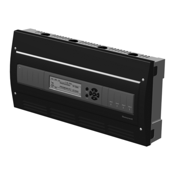
AQ252 Universal Injection/Mixing Boiler Reset Control Panels
Modulating Output: )-10 or 2-10 Vdc for variable speed
pump or modulating boiler
Mixing Valve (Com, O, C): 324 Vac, 0.5A, 12VA
R–C Input (on Control and Zoning Modules): 24 Vac
Class II
R–C Output (on transformer): 38 VA, 24 Vac Class II
Interface and Timings:
User Interface (Setting, Programming): LCD Display
and a 7-button keypad
Setback Program: 7 day, up to 2 setback periods/day.
Boiler Heat Post Purge: Off, 10 seconds to 30 minutes
(factory default is 30 seconds)
Pump/Valve exercise: 30 seconds per 2 weeks of space
heating inactivity
Thermostat Compatibility: Digital non-communicating
thermostats and/or AQ1000 Series 2-wire communicating
thermostats
Supply/Return/Secondary (Mixed) Loop Sensor: 10K ohm
NTC thermistor at 77°F (25°C) ± 0.5°F (±0.3°C). Lead
length: 10 ft. (3.0 m); up to 500 ft. (150 m) using 18 AWG or
larger wire, beta=3892.
Outdoor Sensor: 10K ohm NTC thermistor at 77°F (25°C) ±
0.5°F (±0.3°C). Lead length: 15 ft. (4.6 m); up to 500 ft. (150
m) using 18 AWG or larger wire, beta=3892
Dimensions (HxWxD): 8 x 16 1/2 x 3 3/8 in. (20.3 x 42 x
8.5 cm) approximate
Weight: 4.9 lb. (2.3 kg)
Approvals: Canadian Standards Association: Certified, File
No. LR76030
— Expansion Zoning Panel refers to an assembled
product, consisting of a Zoning Module and (if
applicable) a transformer, contained within an AQ2000
panel enclosure. Expansion Zoning Panels are
available in either 4-zone or 8-zone configurations.
— Zoning Module refers to the component within the
AQ252 Series Control Panel that controls zoning
operations.
When Installing this Product...
1. Read these instructions carefully. Failure to follow
them could damage the product or cause a
hazardous condition.
2. Check the ratings given in the instructions and on
the product to make sure the product is suitable for
the application.
3. Installers must be trained, experienced, and licensed
service technicians.
4. Follow local codes for installation and application.
5. After installation is complete, check out the product
operation as printed in these instructions.
3
69-1986—02
Advertisement

Related Manuals for Honeywell AQ252 Series


Summary of Contents for Honeywell AQ252 Series
- Page 1 — Control Module refers to the component within an 3. Installers must be trained, experienced, and licensed AQ252 Series Control Panel that performs the master service technicians. control operations. See Table 1 on page 2 for specific 4. Follow local codes for installation and application.
- Page 2 AQ252 Universal Injection/Mixing Boiler Reset Control Panels One of two different 4-zone Zoning Modules: WARNING • AQ15740B (part of the AQ25244B Control Panel) for zoning with 24 Vac zone valves with end Risk of electrical shock. switches. Can cause severe injury, property damage or death. •...
- Page 3 Mount the control panel on the wall: Expansion Zoning Panel, ensuring it is level with the 1. Use the template supplied with the AQ252 Series adjoining Control Panel, and install two lower screws. Control Panel to mark mounting holes for panels.
- Page 4 AQ252 Universal Injection/Mixing Boiler Reset Control Panels WIRE CHANNEL PLUGS WIRE CHANNEL PLUGS M23733A Fig. 3. Orientation of wire channel plugs for creating pass-through wire channel and for joining Control Panel to Expansion Zoning Panels. 69-1986—02...
- Page 5 • “Step 4 – Zoning Equipment Wiring” on page 11 document. For additional information, refer to • “Step 5 – Line Voltage System Outputs” on page 13 http:// customer.honeywell.com or your local • “Step 6 – Connection To Line Voltage Power” on page 14 distributor.
- Page 6 AQ252 Universal Injection/Mixing Boiler Reset Control Panels M27685A Fig. 5. Low voltage wiring for the AQ15200B Control Module. Temperature Sensor Wiring SECONDARY (MIXED) LOOP SUPPLY SENSOR The secondary sensor should be installed on the secondary Connect the lead wires of each sensor to the corresponding (mixed) water piping, far enough downstream of the mixing terminals on top of the AQ1520 Control Module.
- Page 7 If Secondary Loop Control: If a 0-10V or 2-10V driven shielded cable is used, Honeywell recommends the variable speed injection pump or a modulating mixing use of shielded cable with a continuous ground plane,...
- Page 8 AQ252 Universal Injection/Mixing Boiler Reset Control Panels AUX-OUT Communication Bus Wiring If the Auxiliary Out low voltage output will be used, wire it now All AQ2000 components communicate with each other on the to the device (e.g., A/C compressor) that will be switched when AQUATROL network using communication bus wiring.
- Page 9 AQ252’s transformer, through the wiring channel across Control Panel. This integral transformer has enough power to operate 4 motorized zone valves (such as Honeywell V8043E valves or 4 valves using low- amperage draw, heat motor actuators, such as Honeywell MV100 actuators), plus power the electronics of the AQ252's Control Module and up to 69-1986—02...
- Page 10 AQ252 Universal Injection/Mixing Boiler Reset Control Panels 16 AQ1000 thermostats. If zone valves with high- CAUTION amperage draw heat-motor actuators are used (such as Taco 500 series zone valves), additional 24 Vac Equipment Damage Hazard. transformer capacity will need to be wired to the Can damage internal circuitry of Zoning Module.
- Page 11 AQ252 Universal Injection/Mixing Boiler Reset Control Panels Step 5 – Line Voltage System Outputs “1. Boiler Pump” “2. DHW Device” Refer to Fig. 15 and follow these steps to wire the devices to “3. Line Voltage Rated Variable Injection Pump” the AQ252 Control Module.
- Page 12 AQ252 Universal Injection/Mixing Boiler Reset Control Panels Setup is enabled in the EQUIPMENT SETUP > SECONDARY NOTE: Use of this output is optional. The Aux. pump dry con- LOOP sub-menu when the INJECT parameter is set to tacts are line voltage-rated but unpowered. A low volt- ENABLE (see Fig.
- Page 13 Panel. 4 PROGRAM AND CONFIGURE THE CONTROL PANEL Only two steps are required to set up the AQ252 Series Control Panel: 1. Check the program settings for the Control Module: Operation of the AQ252's Control Module is set by the menu selections accessible through the Control Module’s LCD screen.
- Page 14 AQ252 Universal Injection/Mixing Boiler Reset Control Panels valves. The valve logic induces a delay before • When using digital 2-stage thermostats (non activating the boiler pump even when zone pumps AQ1000 thermostats), the system set-up process are used. When Zone Synchronization is not changes slightly.
- Page 15 AQ252 Universal Injection/Mixing Boiler Reset Control Panels AQ252 – System Programming and v Press these buttons to scroll up/down in the menu items. Pressing one of these buttons automatically This section describes how to navigate the user interface using saves your current selection, exits the edit mode, the keypad and LCD display, and how to program the AQ252 and moves to the previous or next menu item.
- Page 16 AQ252 Universal Injection/Mixing Boiler Reset Control Panels LCD Display Navigation NOTES: Home Page display upon restart after a power failure of more than four hours: This section describes how the keypad is used to navigate the Upon restarting the AQ252 following a power dis- LCD display and menus.
- Page 17 AQ252 Universal Injection/Mixing Boiler Reset Control Panels Refer to Table 5 on page 25 in the “Appendix” for all of the displayed at the top or bottom of the LCD display (refer to User Menu options for the AQ252 Control Panel, the factory Fig.
- Page 18 The Boiler T-T and Boiler pump relay outputs should de- activate. After the AQ252 Series Control Panel and any AQ255/AQ257 Expansion Zoning Panels have been set up and the entire 5. Repeat steps 3 and 4 for all zones associated with the...