Mitsubishi Electric Got 1000 Manuals
Manuals and User Guides for Mitsubishi Electric Got 1000. We have 5 Mitsubishi Electric Got 1000 manuals available for free PDF download: User Manual, Training Manual, Connection Manual
Mitsubishi Electric Got 1000 User Manual (368 pages)
Brand: Mitsubishi Electric
|
Category: Control Panel
|
Size: 6.4 MB
Table of Contents
Advertisement

Mitsubishi Electric Got 1000 User Manual (310 pages)
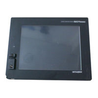
Graphic Operation terminal
Brand: Mitsubishi Electric
|
Category: Touch terminals
|
Size: 5.38 MB
Table of Contents
Mitsubishi Electric Got 1000 Training Manual (200 pages)
Graphic Operation Terminal
Brand: Mitsubishi Electric
|
Category: Touch terminals
|
Size: 7.5 MB
Table of Contents
Advertisement

Mitsubishi Electric Got 1000 User Manual (266 pages)
GRAPHIC OPERATION TERMINAL
Brand: Mitsubishi Electric
|
Category: Touch terminals
|
Size: 5.54 MB
Table of Contents

Mitsubishi Electric Got 1000 Connection Manual (56 pages)
Graphic Operation terminal
Brand: Mitsubishi Electric
|
Category: Touch terminals
|
Size: 1.79 MB
Table of Contents
Advertisement
Related Products
- Mitsubishi Electric GOT 1000 Series
- Mitsubishi Electric GOT2000-GT27
- Mitsubishi Electric GOT2000-GT25
- Mitsubishi Electric GOT2000-GT23
- Mitsubishi Electric GOT2000-GT21
- Mitsubishi Electric GOT2000-Handy GOT
- Mitsubishi Electric GOT1000 GT14
- Mitsubishi Electric GOT-A900 Series
- Mitsubishi Electric GOT DRIVE GOT2000
- Mitsubishi Electric GT115