ABB ACS580-01 Series Drive Manuals
Manuals and User Guides for ABB ACS580-01 Series Drive. We have 6 ABB ACS580-01 Series Drive manuals available for free PDF download: Hardware Manual, Supplement Manual, Quick Installation And Start-Up Manual, Quick Installation Manual
Advertisement

Advertisement
ABB ACS580-01 Series Quick Installation And Start-Up Manual (17 pages)
Frequency converter. NEC types
Brand: ABB
|
Category: Media Converter
|
Size: 6.95 MB
Table of Contents

ABB ACS580-01 Series Quick Installation Manual (2 pages)
Brand: ABB
|
Category: Industrial Equipment
|
Size: 7.47 MB

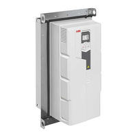
ABB ACS580-01 Series Quick Installation Manual (2 pages)
IP66 / UL Type 4X Flange mounting kit
Brand: ABB
|
Category: Industrial Equipment
|
Size: 2.04 MB
Advertisement