Table of Contents

Related Manuals for Huawei USG6000 Series


Summary of Contents for Huawei USG6000 Series
- Page 1 EPIC Next Generation Firewall Hardware Guide USG6000 Unified Security Gateway V100R001 15333 Avenue of Science, Suite 100 Give us a call: Send us an email: For more info, visit us at: San Diego, CA 92128 1-855-881-2004 info@edgewave.com www.edgewave.com...
- Page 2 EdgeWave Address: 15333 Avenue of Science, Suite 100 San Diego, CA 92128 Website: http://www.edgewave.com Huawei Proprietary and Confidential Issue 03 (2015-01-26) Copyright © Huawei Technologies Co., Ltd.
-
Page 3: About This Document
HUAWEI USG6000 Unified Security Gateway Hardware Guide About This Document About This Document Related Version The following table lists the product version related to this document. Product Name Version The USG6000 series has the V100R001C20SPC700 following models: USG6300 USG6310 − −... - Page 4 HUAWEI USG6000 Unified Security Gateway Hardware Guide About This Document supported expansion cards, preparation before the installation, installation, cabling, and hardware replacement. This document is intended for installation personnel and administrators who install and maintain USG. The installation personnel or administrators must have experience in the installation and maintenance of networking devices.
- Page 5 HUAWEI USG6000 Unified Security Gateway Hardware Guide About This Document Convention Description [ x | y | ... ] Optional items are grouped in brackets and separated by vertical bars. One item is selected or no item is selected. { x | y | ... } Optional items are grouped in braces and separated by vertical bars.
- Page 6 HUAWEI USG6000 Unified Security Gateway Hardware Guide About This Document The following hardware models are added based on V100R001C10: 1.1.1 USG6310 1.1.3 USG6330/6350/6360 1.2.1 USG6530 1.3.1 USG6620/6630 Updates in Issue 01 (2014-06-13) of Product Version V100R001C10SPC100 Initial commercial release.
-
Page 7: Table Of Contents
1.1.4.3 Rear Panel ................................37 1.1.4.4 Power Supply System ............................38 1.1.4.5 Heat Dissipation System ............................41 1.1.4.6 Technical Specifications ............................41 1.2 USG6500 Product Series ............................43 Issue 03 (2015-01-26) Huawei Proprietary and Confidential Copyright © Huawei Technologies Co., Ltd. - Page 8 1.3.4.1 Device Overview ..............................125 1.3.4.2 Front Panel ................................128 1.3.4.3 Rear Panel ................................130 1.3.4.4 Power Supply System ............................137 1.3.4.5 Heat Dissipation System ............................. 141 Issue 03 (2015-01-26) Huawei Proprietary and Confidential Copyright © Huawei Technologies Co., Ltd.
- Page 9 2.4.1 Mounting a Device in a Cabinet ..........................198 2.4.2 Connecting a PGND Cable ............................ 203 2.4.3 Installing an Expansion Card ..........................204 2.4.4 Installing Hard Disk Units ............................. 207 Issue 03 (2015-01-26) Huawei Proprietary and Confidential viii Copyright © Huawei Technologies Co., Ltd.
- Page 10 A.3.2 Humidity, Temperature, and Cleanness ......................... 263 A.3.3 ESD Requirements ..............................264 A.3.4 Lightning Protection and Grounding ........................265 A.3.5 Power Supply ................................ 268 A.3.6 Electromagnetic Protection ........................... 270 Issue 03 (2015-01-26) Huawei Proprietary and Confidential Copyright © Huawei Technologies Co., Ltd.
-
Page 11: Hardware Overview
The USG supports multiple types of expansion cards, which increase the number of interfaces, and bypass cards, which provide enhanced reliability. 1.5 Hard Disk Hard disks store log and report data. Different models support different types of hard disk modules. Issue 03 (2015-01-26) Huawei Proprietary and Confidential Copyright © Huawei Technologies Co., Ltd. -
Page 12: Usg6300 Product Series
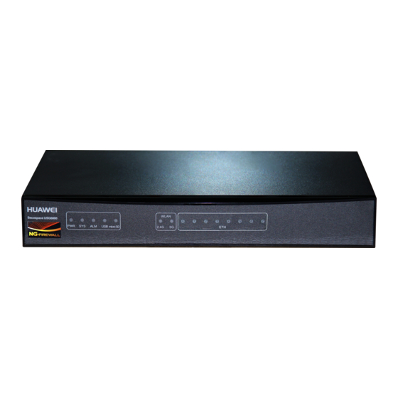
1.1.1.2 Front Panel The USG6310 front panel provides a USB 2.0 port and system and port status indicators. Figure 1-2 illustrates the front panel of the USG6310. Issue 03 (2015-01-26) Huawei Proprietary and Confidential Copyright © Huawei Technologies Co., Ltd. -
Page 13: Rear Panel
Off: The USB 2.0 port is disconnected. 1.1.1.3 Rear Panel The rear panel of the USG6310 provides fixed ports, a protective ground terminal, RST button, and power socket. Issue 03 (2015-01-26) Huawei Proprietary and Confidential Copyright © Huawei Technologies Co., Ltd. - Page 14 ALM indicators on the front panel are both blinking, release the RST button to restore the default settings. Protective ground The M4 OT terminal connects the PGND cable to the ground Issue 03 (2015-01-26) Huawei Proprietary and Confidential Copyright © Huawei Technologies Co., Ltd.
-
Page 15: Power Supply System
Output overvoltage Intermittently stops output and automatically restores output protection after the overvoltage condition is removed. Output short circuit Intermittently provides output and automatically restores Issue 03 (2015-01-26) Huawei Proprietary and Confidential Copyright © Huawei Technologies Co., Ltd. -
Page 16: Heat Dissipation System
The USG6310 has a built-in fan module for heat dissipation. The device provides a left-to-right air flow, as shown in Figure 1-5. The built-in fan module locates at the air exhaust and cannot be removed. Issue 03 (2015-01-26) Huawei Proprietary and Confidential Copyright © Huawei Technologies Co., Ltd. -
Page 17: Technical Specifications
100 V to 240 V, 50 Hz/60 Hz Maximum input voltage (AC) 90 V to 264 V, 47 Hz to 63 Hz Maximum input current 1.0 A Issue 03 (2015-01-26) Huawei Proprietary and Confidential Copyright © Huawei Technologies Co., Ltd. -
Page 18: Usg6320
48 hours or the total period within a year exceeds 15 days, it is regarded as long term. 1.1.2 USG6320 The USG6320 is a 1-U desktop device that provides fixed ports and does not support expansion. Issue 03 (2015-01-26) Huawei Proprietary and Confidential Copyright © Huawei Technologies Co., Ltd. -
Page 19: Device Overview
1.1.2.2 Front Panel The USG6320 front panel provides a USB 2.0 port and system and port status indicators. The front panel of the USG6320 is pictured in Figure 1-7. Issue 03 (2015-01-26) Huawei Proprietary and Confidential Copyright © Huawei Technologies Co., Ltd. -
Page 20: Rear Panel
Off: The USB 2.0 port is disconnected. 1.1.2.3 Rear Panel The rear panel of the USG6320 provides fixed ports, a protective ground terminal, RST button, and power socket. Issue 03 (2015-01-26) Huawei Proprietary and Confidential Copyright © Huawei Technologies Co., Ltd. - Page 21 ALM indicators on the front panel are both blinking, release the RST button to restore the default settings. Protective ground The M4 OT terminal connects the PGND cable to the ground Issue 03 (2015-01-26) Huawei Proprietary and Confidential Copyright © Huawei Technologies Co., Ltd.
-
Page 22: Power Supply System
Output overvoltage Intermittently stops output and automatically restores output protection after the overvoltage condition is removed. Output short circuit Intermittently provides output and automatically restores Issue 03 (2015-01-26) Huawei Proprietary and Confidential Copyright © Huawei Technologies Co., Ltd. -
Page 23: Heat Dissipation System
The USG6320 has a built-in fan module for heat dissipation. The device provides a left-to-right air flow, as shown in Figure 1-10. The built-in fan module locates at the air exhaust and cannot be removed. Issue 03 (2015-01-26) Huawei Proprietary and Confidential Copyright © Huawei Technologies Co., Ltd. -
Page 24: Technical Specifications
100 V to 240 V, 50 Hz/60 Hz Maximum input voltage (AC) 90 V to 264 V, 47 Hz to 63 Hz Maximum input current 1.5 A Issue 03 (2015-01-26) Huawei Proprietary and Confidential Copyright © Huawei Technologies Co., Ltd. - Page 25 15 days. If the continuous operating period exceeds 48 hours or the total period within a year exceeds 15 days, it is regarded as long term. Issue 03 (2015-01-26) Huawei Proprietary and Confidential Copyright © Huawei Technologies Co., Ltd.
-
Page 26: Usg6330/6350/6360
Forwarding plane: parses and processes packets and Issue 03 (2015-01-26) Huawei Proprietary and Confidential Copyright © Huawei Technologies Co., Ltd. - Page 27 Provides eight gigabit RJ45 Ethernet ports. Provides eight gigabit RJ45 ports and two 2XG8GE WSIC Interface Card 10-gigabit SFP+ ports. 8GEF WSIC Interface Card Provides eight gigabit SFP ports. Issue 03 (2015-01-26) Huawei Proprietary and Confidential Copyright © Huawei Technologies Co., Ltd.
-
Page 28: Front Panel
C is the interface number, which begins with 0 and is numbered from bottom to top and left to right. Fixed interface The core component for system control and management. The interface Issue 03 (2015-01-26) Huawei Proprietary and Confidential Copyright © Huawei Technologies Co., Ltd. - Page 29 Fixed interface board Figure 1-13 illustrates the fixed interface board panel of the USG6330/6350/6360. Issue 03 (2015-01-26) Huawei Proprietary and Confidential Copyright © Huawei Technologies Co., Ltd.
- Page 30 HUAWEI USG6000 Unified Security Gateway Hardware Guide 1 Hardware Overview Figure 1-13 Fixed interface board panel of the USG6330/6350/6360 Name Description Issue 03 (2015-01-26) Huawei Proprietary and Confidential Copyright © Huawei Technologies Co., Ltd.
- Page 31 Steady on: The power module works properly. (green) Off: The power module is faulty or the power cable is disconnected. HDD indicator Steady on: The hard disk is running. Issue 03 (2015-01-26) Huawei Proprietary and Confidential Copyright © Huawei Technologies Co., Ltd.
-
Page 32: Rear Panel
The rear panel of the USG6330/6350/6360 provides the power module, protective ground terminal, and hard disk slot for optional hard disk combination. Figure 1-14 illustrates the rear panel of the USG6330/6350/6360. Issue 03 (2015-01-26) Huawei Proprietary and Confidential Copyright © Huawei Technologies Co., Ltd. -
Page 33: Power Supply System
1.1.3.4 Power Supply System By default, the USG6330/6350/6360 has a built-in 150W AC power module, but you can optionally add a 170W power module for 1+1 power redundancy. Issue 03 (2015-01-26) Huawei Proprietary and Confidential Copyright © Huawei Technologies Co., Ltd. - Page 34 Input undervoltage Stops power output and automatically restores power output protection after the input voltage becomes normal. Input overvoltage Stops power output and automatically restores power output Issue 03 (2015-01-26) Huawei Proprietary and Confidential Copyright © Huawei Technologies Co., Ltd.
- Page 35 Rated output voltage 12 V DC Maximum output voltage 11.64 V DC to 12.36 V DC range Maximum output current 12.5 A Maximum output power 150 W Issue 03 (2015-01-26) Huawei Proprietary and Confidential Copyright © Huawei Technologies Co., Ltd.
- Page 36 The power switch allows you to turn on or off the power Power switch output. Power receptacle Connects the C13 plug of the AC power cable. Issue 03 (2015-01-26) Huawei Proprietary and Confidential Copyright © Huawei Technologies Co., Ltd.
- Page 37 Dimensions (H x W x D) 40 mm x 69 mm x 195 mm Weight 0.82 kg Input Rated input voltage range 100 V AC to 240 V AC (50 Hz/60 Hz) Issue 03 (2015-01-26) Huawei Proprietary and Confidential Copyright © Huawei Technologies Co., Ltd.
-
Page 38: Heat Dissipation System
The built-in fan module locates at the air exhaust and cannot be removed. Figure 1-17 System air flow Issue 03 (2015-01-26) Huawei Proprietary and Confidential Copyright © Huawei Technologies Co., Ltd. -
Page 39: Technical Specifications
Air flow (hot air flow, viewed facing the Intake on the front and left sides, exhaust on rear panel) the right side Port density Out-of-band management port 1 (RJ45) Console port 1 (RJ45) Issue 03 (2015-01-26) Huawei Proprietary and Confidential Copyright © Huawei Technologies Co., Ltd. - Page 40 15 days. If the continuous operating period exceeds 48 hours or the total period within a year exceeds 15 days, it is regarded as long term. Issue 03 (2015-01-26) Huawei Proprietary and Confidential Copyright © Huawei Technologies Co., Ltd.
-
Page 41: Usg6370/6380/6390
Forwarding plane: parses and processes packets and Issue 03 (2015-01-26) Huawei Proprietary and Confidential Copyright © Huawei Technologies Co., Ltd. - Page 42 Provides eight gigabit RJ45 ports and two 10-gigabit SFP+ ports. 8GEF WSIC Interface Card Provides eight gigabit SFP ports. 4GE-BYPASS WSIC Card Provides two electrical bypass links. Issue 03 (2015-01-26) Huawei Proprietary and Confidential Copyright © Huawei Technologies Co., Ltd.
-
Page 43: Front Panel
The interface board is built-in and cannot be removed. For details on the ports and indicators on the fixed interface board, see Fixed interface board. Issue 03 (2015-01-26) Huawei Proprietary and Confidential Copyright © Huawei Technologies Co., Ltd. - Page 44 Fixed interface board Figure 1-20 illustrates the fixed interface board panel of the USG6370/6380/6390. Issue 03 (2015-01-26) Huawei Proprietary and Confidential Copyright © Huawei Technologies Co., Ltd.
- Page 45 HUAWEI USG6000 Unified Security Gateway Hardware Guide 1 Hardware Overview Figure 1-20 Fixed interface board panel of the USG6370/6380/6390 Name Description Issue 03 (2015-01-26) Huawei Proprietary and Confidential Copyright © Huawei Technologies Co., Ltd.
- Page 46 Off: The hard disk is not detected. MODE indicator Steady on: Hot standby is not configured, or hot standby is (green) configured but the device is the standby device in an active/standby Issue 03 (2015-01-26) Huawei Proprietary and Confidential Copyright © Huawei Technologies Co., Ltd.
-
Page 47: Rear Panel
The rear panel of the USG6370/6380/6390 provides the power module, protective ground terminal, and hard disk slot for optional hard disk combination. Figure 1-21 illustrates the rear panel of the USG6370/6380/6390. Issue 03 (2015-01-26) Huawei Proprietary and Confidential Copyright © Huawei Technologies Co., Ltd. -
Page 48: Power Supply System
1.1.4.4 Power Supply System By default, the USG6370/6380/6390 has a 170W AC power module, but two power modules are supported for 1+1 power redundancy. Issue 03 (2015-01-26) Huawei Proprietary and Confidential Copyright © Huawei Technologies Co., Ltd. - Page 49 The hole is used to install the power cable clip, which is used to bind and fix the power cable. The power cable clip is installed before shipment. Issue 03 (2015-01-26) Huawei Proprietary and Confidential Copyright © Huawei Technologies Co., Ltd.
- Page 50 Rated input voltage range 100 V AC to 240 V AC (50 Hz/60 Hz) Maximum input voltage 90 V AC to 264 V AC (47 Hz to 63 Hz) range Maximum input current 2.5 A Output Issue 03 (2015-01-26) Huawei Proprietary and Confidential Copyright © Huawei Technologies Co., Ltd.
-
Page 51: Heat Dissipation System
Figure 1-23 System air flow 1.1.4.6 Technical Specifications This section describes the dimensions, weight, and power and environment specifications of the USG6370/6380/6390. Table 1-18 lists the technical specifications of the USG6370/6380/6390. Issue 03 (2015-01-26) Huawei Proprietary and Confidential Copyright © Huawei Technologies Co., Ltd. - Page 52 Port density Out-of-band management port 1 (RJ45) Console port 1 (RJ45) USB 2.0 port Mandatory service ports 4 GE optical ports 8 10/100/1000M autosensing Ethernet Issue 03 (2015-01-26) Huawei Proprietary and Confidential Copyright © Huawei Technologies Co., Ltd.
-
Page 53: Usg6500 Product Series
The USG6500 product series includes USG6530/6550/6570. These models are 1 U devices with an integrated structure and fit into a 19-inch standard cabinet. A larger model number indicates a higher performance. Issue 03 (2015-01-26) Huawei Proprietary and Confidential Copyright © Huawei Technologies Co., Ltd. -
Page 54: Usg6530
Forwarding plane: parses and processes packets and Issue 03 (2015-01-26) Huawei Proprietary and Confidential Copyright © Huawei Technologies Co., Ltd. - Page 55 Provides eight gigabit RJ45 Ethernet ports. Provides eight gigabit RJ45 ports and two 2XG8GE WSIC Interface Card 10-gigabit SFP+ ports. 8GEF WSIC Interface Card Provides eight gigabit SFP ports. Issue 03 (2015-01-26) Huawei Proprietary and Confidential Copyright © Huawei Technologies Co., Ltd.
-
Page 56: Front Panel
Fixed interface The core component for system control and management. The interface board board provides an out-of-band management port, console port, and USB Issue 03 (2015-01-26) Huawei Proprietary and Confidential Copyright © Huawei Technologies Co., Ltd. - Page 57 Fixed interface board Figure 1-26 illustrates the fixed interface board panel of the USG6530. Issue 03 (2015-01-26) Huawei Proprietary and Confidential Copyright © Huawei Technologies Co., Ltd.
- Page 58 HUAWEI USG6000 Unified Security Gateway Hardware Guide 1 Hardware Overview Figure 1-26 Fixed interface board panel of the USG6530 Name Description Issue 03 (2015-01-26) Huawei Proprietary and Confidential Copyright © Huawei Technologies Co., Ltd.
- Page 59 Steady on: The power module works properly. (green) Off: The power module is faulty or the power cable is disconnected. HDD indicator Steady on: The hard disk is running. Issue 03 (2015-01-26) Huawei Proprietary and Confidential Copyright © Huawei Technologies Co., Ltd.
-
Page 60: Rear Panel
The rear panel of the USG6530 provides the power module, protective ground terminal, and hard disk slot for optional hard disk combination. Figure 1-27 illustrates the rear panel of the USG6530. Issue 03 (2015-01-26) Huawei Proprietary and Confidential Copyright © Huawei Technologies Co., Ltd. -
Page 61: Power Supply System
1.2.1.4 Power Supply System By default, the USG6530 has a built-in 150W AC power module, but you can optionally add a 170W power module for 1+1 power redundancy. Issue 03 (2015-01-26) Huawei Proprietary and Confidential Copyright © Huawei Technologies Co., Ltd. - Page 62 Input undervoltage Stops power output and automatically restores power output protection after the input voltage becomes normal. Input overvoltage Stops power output and automatically restores power output Issue 03 (2015-01-26) Huawei Proprietary and Confidential Copyright © Huawei Technologies Co., Ltd.
- Page 63 Rated output voltage 12 V DC Maximum output voltage 11.64 V DC to 12.36 V DC range Maximum output current 12.5 A Maximum output power 150 W Issue 03 (2015-01-26) Huawei Proprietary and Confidential Copyright © Huawei Technologies Co., Ltd.
- Page 64 The power switch allows you to turn on or off the power Power switch output. Power receptacle Connects the C13 plug of the AC power cable. Issue 03 (2015-01-26) Huawei Proprietary and Confidential Copyright © Huawei Technologies Co., Ltd.
- Page 65 Dimensions (H x W x D) 40 mm x 69 mm x 195 mm Weight 0.82 kg Input Rated input voltage range 100 V AC to 240 V AC (50 Hz/60 Hz) Issue 03 (2015-01-26) Huawei Proprietary and Confidential Copyright © Huawei Technologies Co., Ltd.
-
Page 66: Heat Dissipation System
The built-in fan module locates at the air exhaust and cannot be removed. Figure 1-30 System air flow Issue 03 (2015-01-26) Huawei Proprietary and Confidential Copyright © Huawei Technologies Co., Ltd. -
Page 67: Technical Specifications
Air flow (hot air flow, viewed facing the Intake on the front and left sides, exhaust on rear panel) the right side Port density Out-of-band management port 1 (RJ45) Console port 1 (RJ45) Issue 03 (2015-01-26) Huawei Proprietary and Confidential Copyright © Huawei Technologies Co., Ltd. - Page 68 15 days. If the continuous operating period exceeds 48 hours or the total period within a year exceeds 15 days, it is regarded as long term. Issue 03 (2015-01-26) Huawei Proprietary and Confidential Copyright © Huawei Technologies Co., Ltd.
-
Page 69: Usg6550/6570
Forwarding plane: parses and processes packets and Issue 03 (2015-01-26) Huawei Proprietary and Confidential Copyright © Huawei Technologies Co., Ltd. - Page 70 Provides eight gigabit RJ45 ports and two 10-gigabit SFP+ ports. 8GEF WSIC Interface Card Provides eight gigabit SFP ports. 4GE-BYPASS WSIC Card Provides two electrical bypass links. Issue 03 (2015-01-26) Huawei Proprietary and Confidential Copyright © Huawei Technologies Co., Ltd.
-
Page 71: Front Panel
The interface board is built-in and cannot be removed. For details on the ports and indicators on the fixed interface board, see Fixed Interface Board. Expansion slot Provides two WSIC slots. Issue 03 (2015-01-26) Huawei Proprietary and Confidential Copyright © Huawei Technologies Co., Ltd. - Page 72 Fixed Interface Board Figure 1-33 illustrates the fixed interface board panel of the USG6550/6570. Issue 03 (2015-01-26) Huawei Proprietary and Confidential Copyright © Huawei Technologies Co., Ltd.
- Page 73 HUAWEI USG6000 Unified Security Gateway Hardware Guide 1 Hardware Overview Figure 1-33 USG6550/6570 fixed interface board panel Name Description Issue 03 (2015-01-26) Huawei Proprietary and Confidential Copyright © Huawei Technologies Co., Ltd.
- Page 74 Off: The hard disk is not detected. MODE indicator Steady on: Hot standby is not configured, or hot standby is (green) configured but the device is the standby device in an active/standby Issue 03 (2015-01-26) Huawei Proprietary and Confidential Copyright © Huawei Technologies Co., Ltd.
-
Page 75: Rear Panel
The rear panel of the USG6550/6570 provides the power module, protective ground terminal, and hard disk slot for optional hard disk combination. Figure 1-34 illustrates the rear panel of the USG6550/6570. Issue 03 (2015-01-26) Huawei Proprietary and Confidential Copyright © Huawei Technologies Co., Ltd. -
Page 76: Power Supply System
1.2.2.4 Power Supply System By default, the USG6550/6570 has a 170W AC power module, but two power modules are supported for 1+1 power redundancy. Issue 03 (2015-01-26) Huawei Proprietary and Confidential Copyright © Huawei Technologies Co., Ltd. - Page 77 The hole is used to install the power cable clip, which is used to bind and fix the power cable. The power cable clip is installed before shipment. Issue 03 (2015-01-26) Huawei Proprietary and Confidential Copyright © Huawei Technologies Co., Ltd.
- Page 78 Rated input voltage range 100 V AC to 240 V AC (50 Hz/60 Hz) Maximum input voltage 90 V AC to 264 V AC (47 Hz to 63 Hz) range Maximum input current 2.5 A Output Issue 03 (2015-01-26) Huawei Proprietary and Confidential Copyright © Huawei Technologies Co., Ltd.
-
Page 79: Heat Dissipation System
Figure 1-36 System air flow 1.2.2.6 Technical Specifications This section describes the dimensions, weight, and power and environment specifications of the USG6550/6570. Table 1-30 lists the technical specifications of the USG6550/6570. Issue 03 (2015-01-26) Huawei Proprietary and Confidential Copyright © Huawei Technologies Co., Ltd. - Page 80 Port density Out-of-band management port 1 (RJ45) Console port 1 (RJ45) USB 2.0 port Mandatory service ports 4 GE optical ports 8 10/100/1000M autosensing Ethernet Issue 03 (2015-01-26) Huawei Proprietary and Confidential Copyright © Huawei Technologies Co., Ltd.
-
Page 81: Usg6600 Product Series
The USG6600 product series includes USG6620/6630/6650/6660/6670/6680. The USG6600 uses an integrated structure design and fits into a 19-inch standard cabinet. USG6620/6630 has the same appearance and are all 1U devices. USG6650/6660/6670/6680 has the same Issue 03 (2015-01-26) Huawei Proprietary and Confidential Copyright © Huawei Technologies Co., Ltd. -
Page 82: Usg6620/6630
The interface board also has an intelligent awareness engine. Management plane: provides ports for configuration, test, and maintenance and implements such functions as running Issue 03 (2015-01-26) Huawei Proprietary and Confidential Copyright © Huawei Technologies Co., Ltd. - Page 83 Expansion Card Description 8GE WSIC Interface Card Provides eight gigabit RJ45 Ethernet ports. 2XG8GE WSIC Interface Card Provides eight gigabit RJ45 ports and two 10-gigabit SFP+ ports. Issue 03 (2015-01-26) Huawei Proprietary and Confidential Copyright © Huawei Technologies Co., Ltd.
-
Page 84: Front Panel
B is the daughter card number, which is 0 because no daughter card is installed now. C is the interface number, which begins with 0 and is numbered from bottom to top and left to right. Issue 03 (2015-01-26) Huawei Proprietary and Confidential Copyright © Huawei Technologies Co., Ltd. - Page 85 Fixed interface board Figure 1-39 illustrates the fixed interface board panel of the USG6620/6630. Issue 03 (2015-01-26) Huawei Proprietary and Confidential Copyright © Huawei Technologies Co., Ltd.
- Page 86 HUAWEI USG6000 Unified Security Gateway Hardware Guide 1 Hardware Overview Figure 1-39 Fixed interface board panel of the USG6620/6630 Name Description Issue 03 (2015-01-26) Huawei Proprietary and Confidential Copyright © Huawei Technologies Co., Ltd.
- Page 87 Off: The hard disk is not detected. MODE indicator Steady on: Hot standby is not configured, or hot standby is (green) configured but the device is the standby device in an active/standby Issue 03 (2015-01-26) Huawei Proprietary and Confidential Copyright © Huawei Technologies Co., Ltd.
-
Page 88: Rear Panel
The rear panel of the USG6620/6630 provides the power module, protective ground terminal, and hard disk slot for optional hard disk combination. Figure 1-40 illustrates the rear panel of the USG6620/6630. Issue 03 (2015-01-26) Huawei Proprietary and Confidential Copyright © Huawei Technologies Co., Ltd. -
Page 89: Power Supply System
1.3.1.4 Power Supply System By default, the USG6620/6630 has a 170W AC power module, but two power modules are supported for 1+1 power redundancy. Issue 03 (2015-01-26) Huawei Proprietary and Confidential Copyright © Huawei Technologies Co., Ltd. - Page 90 The hole is used to install the power cable clip, which is used to bind and fix the power cable. The power cable clip is installed before shipment. Issue 03 (2015-01-26) Huawei Proprietary and Confidential Copyright © Huawei Technologies Co., Ltd.
- Page 91 Rated input voltage range 100 V AC to 240 V AC (50 Hz/60 Hz) Maximum input voltage 90 V AC to 264 V AC (47 Hz to 63 Hz) range Maximum input current 2.5 A Output Issue 03 (2015-01-26) Huawei Proprietary and Confidential Copyright © Huawei Technologies Co., Ltd.
-
Page 92: Heat Dissipation System
Figure 1-42 System air flow 1.3.1.6 Technical Specifications This section describes the dimensions, weight, and power and environment specifications of the USG6620/6630. Table 1-35 lists the technical specifications of the USG6620/6630. Issue 03 (2015-01-26) Huawei Proprietary and Confidential Copyright © Huawei Technologies Co., Ltd. - Page 93 Out-of-band management port 1 (RJ45) Console port 1 (RJ45) USB 2.0 port Mandatory service ports 4 GE optical ports 8 10/100/1000M autosensing Ethernet electrical ports Issue 03 (2015-01-26) Huawei Proprietary and Confidential Copyright © Huawei Technologies Co., Ltd.
-
Page 94: Usg6650/6660
The USG6650/6660 has a 2XG8GE expansion card and an 8GEF expansion card by default; USG6650 has only AC models, and USG6660 has both AC and DC models. Issue 03 (2015-01-26) Huawei Proprietary and Confidential Copyright © Huawei Technologies Co., Ltd. -
Page 95: Device Overview
You can also add some optional modules, such as hard disk and expansion cards, to improve system reliability and add more ports. Appearance Figure 1-43 illustrates the appearance of the USG6650/6660. Issue 03 (2015-01-26) Huawei Proprietary and Confidential Copyright © Huawei Technologies Co., Ltd. - Page 96 Hardware Guide 1 Hardware Overview Figure 1-43 Appearance of USG6650/6660 Table 1-36 describes the functions of the USG6650/6660 components. Table 1-36 Functions of the USG6650/6660 components Name Description Issue 03 (2015-01-26) Huawei Proprietary and Confidential Copyright © Huawei Technologies Co., Ltd.
- Page 97 Ensures normal air flow and keeps out dust. Ports The SPUA provides the following fixed ports: 1 out-of-band management port (RJ45) 1 console port (RJ45) Issue 03 (2015-01-26) Huawei Proprietary and Confidential Copyright © Huawei Technologies Co., Ltd.
-
Page 98: Front Panel
By default, the USG6650/6660 front panel has a 2XG8GE interface card, an 8GEF interface card, a protective ground terminal, an ESD jack, and some expansion slots. The front panel of the USG6650/6660 is pictured in Figure 1-44. Issue 03 (2015-01-26) Huawei Proprietary and Confidential Copyright © Huawei Technologies Co., Ltd. - Page 99 XSIC slot, install a filler panel on the empty upper part of the slot to ensure a normal air flow and keep out dust. Issue 03 (2015-01-26) Huawei Proprietary and Confidential Copyright © Huawei Technologies Co., Ltd.
-
Page 100: Rear Panel
1.3.2.3 Rear Panel The USG6650/6660 rear panel provides power modules, a fan module, and boards, such as SPU. Figure 1-45 illustrates the rear panel of the USG6650/6660. Issue 03 (2015-01-26) Huawei Proprietary and Confidential Copyright © Huawei Technologies Co., Ltd. - Page 101 For details, see 1.3.2.4 Power Supply System. Fan module (in slot The fan module provides air flow for heat dissipation. The slot Issue 03 (2015-01-26) Huawei Proprietary and Confidential Copyright © Huawei Technologies Co., Ltd.
- Page 102 For the wrist strap to be effective, ensure that the device is already grounded. SPUA (the main processing unit) The SPUA is pictured in Figure 1-46. Issue 03 (2015-01-26) Huawei Proprietary and Confidential Copyright © Huawei Technologies Co., Ltd.
- Page 103 (red) Off: HDD0 or HDD1 hard disk is running normally. HDD0 or HDD1 hard Steady on: HDD0 or HDD1 hard disk is present. Issue 03 (2015-01-26) Huawei Proprietary and Confidential Copyright © Huawei Technologies Co., Ltd.
- Page 104 Press and hold down the RST button and power on the device. Three to five seconds later, when the MODE indicator on SPUA is blinking, release the RST button to restore the default settings. Issue 03 (2015-01-26) Huawei Proprietary and Confidential Copyright © Huawei Technologies Co., Ltd.
-
Page 105: Power Supply System
350 W AC Power Module The 350 W AC power module converts AC power to DC power for the device. Figure 1-47 illustrates the appearance of the AC power module. Issue 03 (2015-01-26) Huawei Proprietary and Confidential Copyright © Huawei Technologies Co., Ltd. - Page 106 350 W AC power module. Table 1-39 Functions of the 350 W AC power module Item Description Input undervoltage Stops power output and automatically restores power output Issue 03 (2015-01-26) Huawei Proprietary and Confidential Copyright © Huawei Technologies Co., Ltd.
- Page 107 90 V AC to 264 V AC (47 Hz to 63 Hz) range Maximum input current Output Rated output voltage 12 V DC Maximum output voltage 11.64 V DC to 12.36 V DC Issue 03 (2015-01-26) Huawei Proprietary and Confidential Copyright © Huawei Technologies Co., Ltd.
- Page 108 (except hiccup mode protection state, in which the indicator blinks). Power cable terminal Connect the black wire to the RTN (+) terminal and the blue Issue 03 (2015-01-26) Huawei Proprietary and Confidential Copyright © Huawei Technologies Co., Ltd.
- Page 109 Table 1-42 Technical specifications of the 350 W DC power module Item Description Silkscreen PWR350D Dimensions (H x W x D) 38.5 mm x 201.0 mm × 260.5 mm Weight 1.50 kg Issue 03 (2015-01-26) Huawei Proprietary and Confidential Copyright © Huawei Technologies Co., Ltd.
-
Page 110: Heat Dissipation System
The fan module locates at the air exhaust of the system. Issue 03 (2015-01-26) Huawei Proprietary and Confidential Copyright © Huawei Technologies Co., Ltd. - Page 111 The fan module supports hot swapping. The fan module consists of a fan tray, fans, and a fan control board (FCB). Figure 1-50 illustrates the appearance of the fan module. Issue 03 (2015-01-26) Huawei Proprietary and Confidential Copyright © Huawei Technologies Co., Ltd.
- Page 112 13 FAN means that the fan module is installed in slot The serial number that uniquely identifies the fan module. ESD jack The equipment end of the wrist strap is inserted into the ESD Issue 03 (2015-01-26) Huawei Proprietary and Confidential Copyright © Huawei Technologies Co., Ltd.
-
Page 113: Technical Specifications
DDR3 16 GB Flash 64 MB CF card 2 GB Hard disk Optional. The device can hold two 300GB 2.5-inch SAS hard disks to form a RAID-1 Issue 03 (2015-01-26) Huawei Proprietary and Confidential Copyright © Huawei Technologies Co., Ltd. - Page 114 2 10GE optical ports Expansion slot 6 WSIC slots or 2 WSIC slot + 4 XSIC slots Types of expansion cards 8GE-WSIC-8×1GE RJ45 interface card 2XG8GE-WSIC-8×1GE RJ45+2×10GE Issue 03 (2015-01-26) Huawei Proprietary and Confidential Copyright © Huawei Technologies Co., Ltd.
-
Page 115: Usg6670
You can also add some optional modules, such as hard disk and expansion cards, to improve system reliability and add more ports. Issue 03 (2015-01-26) Huawei Proprietary and Confidential Copyright © Huawei Technologies Co., Ltd. - Page 116 Hardware Guide 1 Hardware Overview Appearance Figure 1-51 illustrates the appearance of the USG6670. Figure 1-51 Appearance of USG6670 Table 1-45 describes the functions of the USG6670 components. Issue 03 (2015-01-26) Huawei Proprietary and Confidential Copyright © Huawei Technologies Co., Ltd.
- Page 117 Filler panel Ensures normal air flow and keeps out dust. Ports The SPUA provides the following fixed ports: 1 out-of-band management port (RJ45) Issue 03 (2015-01-26) Huawei Proprietary and Confidential Copyright © Huawei Technologies Co., Ltd.
-
Page 118: Front Panel
By default, the USG6670 front panel has two 2XG8GE interface cards, one 8GEF interface card, a protective ground terminal, an ESD jack, and some expansion slots. The front panel of the USG6670 is pictured in Figure 1-52. Issue 03 (2015-01-26) Huawei Proprietary and Confidential Copyright © Huawei Technologies Co., Ltd. - Page 119 The interfaces on the interface card are numbered from GigabitEthernet 2/0/0 to GigabitEthernet 2/0/7 (left to right). For details on the interface card, see 1.4.3 8GEF WSIC Interface Card. Issue 03 (2015-01-26) Huawei Proprietary and Confidential Copyright © Huawei Technologies Co., Ltd.
-
Page 120: Rear Panel
1.3.3.3 Rear Panel The USG6670 rear panel provides power modules, a fan module, and boards, such as SPU. Figure 1-53 illustrates the rear panel of the USG6670. Issue 03 (2015-01-26) Huawei Proprietary and Confidential Copyright © Huawei Technologies Co., Ltd. - Page 121 For details, see 1.3.3.4 Power Supply System. Fan module (in slot The fan module provides air flow for heat dissipation. The slot Issue 03 (2015-01-26) Huawei Proprietary and Confidential Copyright © Huawei Technologies Co., Ltd.
- Page 122 For the wrist strap to be effective, ensure that the device is already grounded. SPUA (the main processing unit) The SPUA is pictured in Figure 1-54. Issue 03 (2015-01-26) Huawei Proprietary and Confidential Copyright © Huawei Technologies Co., Ltd.
- Page 123 (red) Off: HDD0 or HDD1 hard disk is running normally. HDD0 or HDD1 hard Steady on: HDD0 or HDD1 hard disk is present. Issue 03 (2015-01-26) Huawei Proprietary and Confidential Copyright © Huawei Technologies Co., Ltd.
- Page 124 Press and hold down the RST button and power on the device. Three to five seconds later, when the MODE indicator on SPUA is blinking, release the RST button to restore the default settings. Issue 03 (2015-01-26) Huawei Proprietary and Confidential Copyright © Huawei Technologies Co., Ltd.
-
Page 125: Power Supply System
350 W AC Power Module The 350 W AC power module converts AC power to DC power for the device. Figure 1-55 illustrates the appearance of the AC power module. Issue 03 (2015-01-26) Huawei Proprietary and Confidential Copyright © Huawei Technologies Co., Ltd. - Page 126 350 W AC power module. Table 1-48 Functions of the 350 W AC power module Item Description Input undervoltage Stops power output and automatically restores power output Issue 03 (2015-01-26) Huawei Proprietary and Confidential Copyright © Huawei Technologies Co., Ltd.
- Page 127 90 V AC to 264 V AC (47 Hz to 63 Hz) range Maximum input current Output Rated output voltage 12 V DC Maximum output voltage 11.64 V DC to 12.36 V DC Issue 03 (2015-01-26) Huawei Proprietary and Confidential Copyright © Huawei Technologies Co., Ltd.
- Page 128 (except hiccup mode protection state, in which the indicator blinks). Power cable terminal Connect the black wire to the RTN (+) terminal and the blue Issue 03 (2015-01-26) Huawei Proprietary and Confidential Copyright © Huawei Technologies Co., Ltd.
- Page 129 Table 1-51 Technical specifications of the 350 W DC power module Item Description Silkscreen PWR350D Dimensions (H x W x D) 38.5 mm x 201.0 mm × 260.5 mm Weight 1.50 kg Issue 03 (2015-01-26) Huawei Proprietary and Confidential Copyright © Huawei Technologies Co., Ltd.
-
Page 130: Heat Dissipation System
The fan module locates at the air exhaust of the system. Issue 03 (2015-01-26) Huawei Proprietary and Confidential Copyright © Huawei Technologies Co., Ltd. - Page 131 The fan module supports hot swapping. The fan module consists of a fan tray, fans, and a fan control board (FCB). Figure 1-58 illustrates the appearance of the fan module. Issue 03 (2015-01-26) Huawei Proprietary and Confidential Copyright © Huawei Technologies Co., Ltd.
- Page 132 13 FAN means that the fan module is installed in slot The serial number that uniquely identifies the fan module. ESD jack The equipment end of the wrist strap is inserted into the ESD Issue 03 (2015-01-26) Huawei Proprietary and Confidential Copyright © Huawei Technologies Co., Ltd.
-
Page 133: Technical Specifications
DDR3 16 GB Flash 64 MB CF card 2 GB Hard disk Optional. The device can hold two 300GB 2.5-inch SAS hard disks to form a RAID-1 Issue 03 (2015-01-26) Huawei Proprietary and Confidential Copyright © Huawei Technologies Co., Ltd. - Page 134 4 10GE optical ports Expansion slot 5 WSIC slots or 1 WSIC slot + 4 XSIC slots Types of expansion cards 8GE-WSIC-8×1GE RJ45 interface card 2XG8GE-WSIC-8×1GE RJ45+2×10GE Issue 03 (2015-01-26) Huawei Proprietary and Confidential Copyright © Huawei Technologies Co., Ltd.
-
Page 135: Usg6680
SPUB (service engine), interface card, power module, and fan module. You can also add some optional modules, such as hard disk and expansion cards, to improve system reliability and add more ports. Issue 03 (2015-01-26) Huawei Proprietary and Confidential Copyright © Huawei Technologies Co., Ltd. - Page 136 Hardware Guide 1 Hardware Overview Appearance Figure 1-59 illustrates the appearance of the USG6680. Figure 1-59 Appearance of USG6680 Table 1-54 describes the functions of the USG6680 components. Issue 03 (2015-01-26) Huawei Proprietary and Confidential Copyright © Huawei Technologies Co., Ltd.
- Page 137 However, to prevent overheating, do not operate the device without a functioning fan module for more than one minute. Issue 03 (2015-01-26) Huawei Proprietary and Confidential Copyright © Huawei Technologies Co., Ltd.
-
Page 138: Front Panel
By default, the USG6680 front panel has two 2XG8GE interface cards, one 8GEF interface card, a protective ground terminal, an ESD jack, and some expansion slots. The front panel of the USG6680 is pictured in Figure 1-60. Issue 03 (2015-01-26) Huawei Proprietary and Confidential Copyright © Huawei Technologies Co., Ltd. - Page 139 The interfaces on the interface card are numbered from GigabitEthernet 2/0/0 to GigabitEthernet 2/0/7 (left to right). For details on the interface card, see 1.4.3 8GEF WSIC Interface Card. Issue 03 (2015-01-26) Huawei Proprietary and Confidential Copyright © Huawei Technologies Co., Ltd.
-
Page 140: Rear Panel
1.3.4.3 Rear Panel The USG6680 rear panel provides power modules, a fan module, and boards, such as SPU. The rear panel of the USG6680 is pictured in Figure 1-61. Issue 03 (2015-01-26) Huawei Proprietary and Confidential Copyright © Huawei Technologies Co., Ltd. - Page 141 SPUA can optionally provide a hard disk (SM-HDD-SAS300G-A) as required. SPUA is installed in slot SPU11 and cannot be removed. For details, see SPUA (the main processing unit). Issue 03 (2015-01-26) Huawei Proprietary and Confidential Copyright © Huawei Technologies Co., Ltd.
- Page 142 For the wrist strap to be effective, ensure that the device is already grounded. SPUA (the main processing unit) The SPUA is pictured in Figure 1-62. Issue 03 (2015-01-26) Huawei Proprietary and Confidential Copyright © Huawei Technologies Co., Ltd.
- Page 143 (red) Off: HDD0 or HDD1 hard disk is running normally. HDD0 or HDD1 hard Steady on: HDD0 or HDD1 hard disk is present. Issue 03 (2015-01-26) Huawei Proprietary and Confidential Copyright © Huawei Technologies Co., Ltd.
- Page 144 Press and hold down the RST button and power on the device. Three to five seconds later, when the MODE indicator on SPUA is blinking, release the RST button to restore the default settings. Issue 03 (2015-01-26) Huawei Proprietary and Confidential Copyright © Huawei Technologies Co., Ltd.
- Page 145 Dimensions (H x W x D) 40.14 mm x 402.80 mm × 270.00 mm Weight 1 kg Power 109 W SPUB (the service engine) The SPUB is pictured in Figure 1-63. Issue 03 (2015-01-26) Huawei Proprietary and Confidential Copyright © Huawei Technologies Co., Ltd.
- Page 146 Table 1-57 SPUB specifications Item Description Silkscreen SPUB Dimensions (H x W x D) 40.14 mm x 402.80 mm × 270.00 mm Weight 0.8 kg Power 74.8 W Issue 03 (2015-01-26) Huawei Proprietary and Confidential Copyright © Huawei Technologies Co., Ltd.
-
Page 147: Power Supply System
Power receptacle Connects the C13 plug of the AC power cable. Clip hole The hole is used to install the power cable clip, which is used Issue 03 (2015-01-26) Huawei Proprietary and Confidential Copyright © Huawei Technologies Co., Ltd. - Page 148 Table 1-59 Technical specifications of the 700 W AC power module Item Description Silkscreen PAC-700WA-L Dimensions (H x W x D) 38.5 mm x 201.0 mm × 260.5 mm Weight 1.45 kg Input Issue 03 (2015-01-26) Huawei Proprietary and Confidential Copyright © Huawei Technologies Co., Ltd.
- Page 149 The 350 W DC power module is a DC-input and DC-output power module. Figure 1-65 illustrates the appearance of the DC power module. Figure 1-65 Appearance of the 350 W DC power module Issue 03 (2015-01-26) Huawei Proprietary and Confidential Copyright © Huawei Technologies Co., Ltd.
- Page 150 The device has 1+1 power module redundancy. You can hot-swap a power module without interrupting device operation. Table 1-61 lists the technical specifications of the 350 W DC power module. Issue 03 (2015-01-26) Huawei Proprietary and Confidential Copyright © Huawei Technologies Co., Ltd.
-
Page 151: Heat Dissipation System
The fan module locates at the air exhaust of the system. Issue 03 (2015-01-26) Huawei Proprietary and Confidential Copyright © Huawei Technologies Co., Ltd. - Page 152 The fan module supports hot swapping. The fan module consists of a fan tray, fans, and a fan control board (FCB). Figure 1-67 illustrates the appearance of the fan module. Issue 03 (2015-01-26) Huawei Proprietary and Confidential Copyright © Huawei Technologies Co., Ltd.
- Page 153 13 FAN means that the fan module is installed in slot The serial number that uniquely identifies the fan module. ESD jack The equipment end of the wrist strap is inserted into the ESD Issue 03 (2015-01-26) Huawei Proprietary and Confidential Copyright © Huawei Technologies Co., Ltd.
- Page 154 DDR3 16 GB Flash 64 MB CF card 2 GB Hard disk Optional. The device can hold two 300GB 2.5-inch SAS hard disks to form a RAID-1 Issue 03 (2015-01-26) Huawei Proprietary and Confidential Copyright © Huawei Technologies Co., Ltd.
- Page 155 8 GE optical ports 16 10/100/1000M autosensing Ethernet electrical ports 4 10GE optical ports Expansion slot 5 WSIC slots or 1 WSIC slot + 4 XSIC slots Issue 03 (2015-01-26) Huawei Proprietary and Confidential Copyright © Huawei Technologies Co., Ltd.
-
Page 156: Expansion Card
48 hours or the total period within a year exceeds 15 days, it is regarded as long term. 1.4 Expansion Card The USG supports multiple types of expansion cards, which increase the number of interfaces, and bypass cards, which provide enhanced reliability. Issue 03 (2015-01-26) Huawei Proprietary and Confidential Copyright © Huawei Technologies Co., Ltd. -
Page 157: 8Ge Wsic Interface Card
Table 1-64 Attributes of ports on the 8GE card Attribute Description Connector type RJ45 Cable Standard Ethernet cable Working mode Full-duplex/Half-duplex Rate 10/100/1000 Mbit/s autosensing Port standard IEEE 802.2/802.3 Frame format Ethernet_II Network protocol TCP/IP Issue 03 (2015-01-26) Huawei Proprietary and Confidential Copyright © Huawei Technologies Co., Ltd. -
Page 158: 2Xg8Ge Wsic Interface Card
10-gigabit SFP+ port: The port number is 9, and the port Port 1 (SFP+) connects to the 10GE Optical Transceiver. Indicators LINK indicator (green) Steady on: The link is connected. Issue 03 (2015-01-26) Huawei Proprietary and Confidential Copyright © Huawei Technologies Co., Ltd. - Page 159 Port cable Optical fiber (The port requires a 10-gigabit optical transceiver.) Working mode Full duplex Rate 10 Gbit/s Port standard IEEE 802.3ae Frame format Ethernet_II Network protocol TCP/IP Issue 03 (2015-01-26) Huawei Proprietary and Confidential Copyright © Huawei Technologies Co., Ltd.
-
Page 160: 8Gef Wsic Interface Card
Blink: Data is being sent or received through the port. Off: The link of the port is disconnected. Port Description Table 1-68 lists the attributes of ports on the 8GEF card. Issue 03 (2015-01-26) Huawei Proprietary and Confidential Copyright © Huawei Technologies Co., Ltd. -
Page 161: 4Ge-Bypass Wsic Card
When the USG is powered off or becomes faulty, the data on Layer 2 links bypasses the USG and is transmitted between the upstream and downstream devices, ensuring Issue 03 (2015-01-26) Huawei Proprietary and Confidential Copyright © Huawei Technologies Co., Ltd. - Page 162 Steady on: The card is powered on. The bypass formed by GE2 and GE3 is in protection state. Blink: The card is powered on. The bypass formed by GE2 Issue 03 (2015-01-26) Huawei Proprietary and Confidential Copyright © Huawei Technologies Co., Ltd.
- Page 163 Dimensions (H x W x D) 19.82 mm x 201.00 mm x 230.00 mm Weight 0.5 kg Power 13.6 W Available slot WSIC or lower part of the XSIC slot Issue 03 (2015-01-26) Huawei Proprietary and Confidential Copyright © Huawei Technologies Co., Ltd.
-
Page 164: Hard Disk
Figure 1-72 Appearance of the hard disk unit SM-HDD-SAS300G-A Name Description Hard disk tray The hard disk tray supports and holds the hard disk and facilitates hard disk insertion or removal. Issue 03 (2015-01-26) Huawei Proprietary and Confidential Copyright © Huawei Technologies Co., Ltd. -
Page 165: Hard Disk Combination Sm-Hdd-Sas300G-B
Stores log and report data. Hard disk unit SM-HDD-SAS300G-A is hot-swappable, but the hard disk card is not. Appearance Figure 1-73 illustrates the appearance of the hard disk combination SM-HDD-SAS300G-B. Issue 03 (2015-01-26) Huawei Proprietary and Confidential Copyright © Huawei Technologies Co., Ltd. - Page 166 Off: The hard disk is not detected. Technical Specifications Table 1-73 lists the technical specifications of the hard disk combination SM-HDD-SAS300G-B. Issue 03 (2015-01-26) Huawei Proprietary and Confidential Copyright © Huawei Technologies Co., Ltd.
- Page 167 Dimensions (H x W x D) 40.2 mm x 103 mm × 196 mm Capacity 300 GB Hard disk unit port type SAS 6Gbit/s Rotational speed 10000 RPM Power 15 W Issue 03 (2015-01-26) Huawei Proprietary and Confidential Copyright © Huawei Technologies Co., Ltd.
-
Page 168: Hardware Installation
Misoperation may cause personal injury or damage to the USG. This section describes common precautions related to installation. For more precautions, see Safety and Regulatory Compliance Information. Issue 03 (2015-01-26) Huawei Proprietary and Confidential Copyright © Huawei Technologies Co., Ltd. -
Page 169: Installation Environment Check
2.1.2 Installation Environment Check Before you install a USG, verify that the installation environment meets requirements to ensure the normal running and extended life time of the USG. Issue 03 (2015-01-26) Huawei Proprietary and Confidential Copyright © Huawei Technologies Co., Ltd. -
Page 170: Instruments Required For The Installation
Hammer drill: used to drill mounting holes during wall-mounting. Vacuum cleaner: used to remove dust and debris produced while drilling holes. Hammer: used to drive the hollow wall anchors into mounting holes. Issue 03 (2015-01-26) Huawei Proprietary and Confidential Copyright © Huawei Technologies Co., Ltd. -
Page 171: Installing A Desktop Device (Usg6310/6320)
USG6310/6320 on a workbench or a wall. 2.2.1.1 Mounting a Device in a Cabinet The USG6310/6320 can be mounted in a 19-inch standard cabinet using mounting ears. Issue 03 (2015-01-26) Huawei Proprietary and Confidential Copyright © Huawei Technologies Co., Ltd. - Page 172 Figure 2-1. Figure 2-1 Installing the mounting ears on the chassis Step 2 Install floating nuts. Figure 2-2 illustrates the positions of floating nuts. Issue 03 (2015-01-26) Huawei Proprietary and Confidential Copyright © Huawei Technologies Co., Ltd.
- Page 173 Use a Phillips screwdriver to fix M6 screws into two floating nuts of the lower row but do not secure them, leaving a 2 mm spacing, as shown in Figure 2-4. Issue 03 (2015-01-26) Huawei Proprietary and Confidential Copyright © Huawei Technologies Co., Ltd.
- Page 174 Use a Phillips screwdriver to secure the M6 screws, install M6 screws for the upper row, and fix the USG into the cabinet through mounting ears, as shown in Figure 2-5. Issue 03 (2015-01-26) Huawei Proprietary and Confidential Copyright © Huawei Technologies Co., Ltd.
-
Page 175: Mounting A Device On A Workbench
Four rubber feet are delivered with the USG, and four round notches are located at the bottom of the device to hold the rubber feet. Procedure Step 1 Fix the rubber feet to the round notches at the bottom of the USG. Issue 03 (2015-01-26) Huawei Proprietary and Confidential Copyright © Huawei Technologies Co., Ltd. -
Page 176: Mounting A Device Against A Wall
2.2.1.3 Mounting a Device Against a Wall When no cabinet is available, you can mount the USG6310/6320 on a wall. The customer must have screws for wall-mounting. Issue 03 (2015-01-26) Huawei Proprietary and Confidential Copyright © Huawei Technologies Co., Ltd. - Page 177 Ensure that the height of mounting holes is proper so that the indicators are easy to view. Figure 2-7 Spacing between mounting holes Step 2 Drill holes and install mounting screws. Issue 03 (2015-01-26) Huawei Proprietary and Confidential Copyright © Huawei Technologies Co., Ltd.
- Page 178 The USG supports upward mounting and downward mounting. To prevent water from entering into ports and causing device damage, you are advised to mount the USG with ports facing downward. Issue 03 (2015-01-26) Huawei Proprietary and Confidential Copyright © Huawei Technologies Co., Ltd.
-
Page 179: Connecting A Pgnd Cable
Before using the USG6310/6320, correctly connect the PGND cable. Prerequisites The USG has been installed inside a cabinet. Context Instruments required: Phillips screwdriver Multimeter Issue 03 (2015-01-26) Huawei Proprietary and Confidential Copyright © Huawei Technologies Co., Ltd. -
Page 180: Connecting A Console Cable
PC to access the command configuration interface of the USG6310/6320. Context Before connecting a console cable, perform the following operations: Check preparations. Issue 03 (2015-01-26) Huawei Proprietary and Confidential Copyright © Huawei Technologies Co., Ltd. - Page 181 The labels at both ends of a cable are correct, clear, neat, and facing the same direction. Cables and connectors are free of damage or breakage and are connected properly. Issue 03 (2015-01-26) Huawei Proprietary and Confidential Copyright © Huawei Technologies Co., Ltd.
- Page 182 Download the PuTTY software to the local device and double-click it to run the software. Choose Session set the Connection type to Serial. Set the PuTTY parameters. Issue 03 (2015-01-26) Huawei Proprietary and Confidential Copyright © Huawei Technologies Co., Ltd.
-
Page 183: Connecting An Ethernet Cable
The engineering document should specify the cabling route from the cabinet to the peer device in the equipment room, and the length of the cable is calculated based on the cabling path. Label the cable. Issue 03 (2015-01-26) Huawei Proprietary and Confidential Copyright © Huawei Technologies Co., Ltd. - Page 184 Step 4 Remove the temporary labels and attach labels (2 cm away from connectors) at both ends of the Ethernet cable. ----End Follow-up Procedure Verify the following after the installation: Issue 03 (2015-01-26) Huawei Proprietary and Confidential Copyright © Huawei Technologies Co., Ltd.
-
Page 185: Connecting A Power Adapter
Plug the other end of the AC power cable to the AC power socket or the output of the AC power supply device. The USG does not have any power switch. The power supply switch determines the power-on and power-off of the USG. Issue 03 (2015-01-26) Huawei Proprietary and Confidential Copyright © Huawei Technologies Co., Ltd. -
Page 186: Powering On Or Off The Usg6310/6320
The power cable and PGND cable are properly connected. The power switch in the equipment room is easy to locate so that you can power off devices in the case of accidents. Issue 03 (2015-01-26) Huawei Proprietary and Confidential Copyright © Huawei Technologies Co., Ltd. -
Page 187: Installing A 1 U Device (Usg6330/6350/6360/6370/6380/6390/6530/6550/6570/6620/6630)
For details, refer to the Administrator Guide. 2.3 Installing a 1 U Device (USG6330/6350/6360/6370/6380/6390/6530/6550/6570/6620/66 This chapter provides the cabinet-mounting, workbench-mounting, cable connection, and expansion card installation methods of the USG6330/6350/6360/6370/6380/6390/6530/6550/6570/6620/6630 series. Issue 03 (2015-01-26) Huawei Proprietary and Confidential Copyright © Huawei Technologies Co., Ltd. -
Page 188: Mounting A Device To A Specified Location
Step 1 Install mounting ears on the chassis. Use a Phillips screwdriver to fix the mounting ears to both sides of the chassis with M4 screws, as shown in Figure 2-16. Issue 03 (2015-01-26) Huawei Proprietary and Confidential Copyright © Huawei Technologies Co., Ltd. - Page 189 Figure 2-17 Positions of the guide rails and floating nuts Use M6 screws to fix the floating nuts at the positions specified in Figure 2-17, as shown Figure 2-18. Issue 03 (2015-01-26) Huawei Proprietary and Confidential Copyright © Huawei Technologies Co., Ltd.
- Page 190 Figure 2-17. Then use the Philips screws to fix the adjustable guide rails inside the cabinet with M6 screws, as shown in Figure 2-20. Issue 03 (2015-01-26) Huawei Proprietary and Confidential Copyright © Huawei Technologies Co., Ltd.
- Page 191 Lift the USG, move it to the cabinet, place it onto the guide rails, and push it into the cabinet. Use M6 screws to fix the mounting ears of the USG to the mounting rack, as shown in Figure 2-21. Issue 03 (2015-01-26) Huawei Proprietary and Confidential Copyright © Huawei Technologies Co., Ltd.
-
Page 192: Mounting A Device On A Workbench
Clean, firm, and securely installed. Four rubber feet are delivered with the USG, and four round notches are located at the bottom of the device to hold the rubber feet. Issue 03 (2015-01-26) Huawei Proprietary and Confidential Copyright © Huawei Technologies Co., Ltd. - Page 193 Figure 2-22 Placing the USG with rubber feet on a workbench ----End Follow-up Procedure Verify the following after the installation: The USG is securely placed on the workbench. Issue 03 (2015-01-26) Huawei Proprietary and Confidential Copyright © Huawei Technologies Co., Ltd.
-
Page 194: Connecting A Pgnd Cable
Step 3 Connect the M6 end of the PGND cable to the ground terminal of the cabinet or workbench. Figure 2-23 Connecting a PGND cable Issue 03 (2015-01-26) Huawei Proprietary and Confidential Copyright © Huawei Technologies Co., Ltd. -
Page 195: Installing An Expansion Card
Open the ejector lever on an expansion card and push the expansion card along the guide rails of the slot until the ejector lever touches the front panel. Issue 03 (2015-01-26) Huawei Proprietary and Confidential Copyright © Huawei Technologies Co., Ltd. - Page 196 Filler panels are inserted in vacant slots. You must insert filler panels in the vacant slots on the USG to prevent dust and ensure heat dissipation. Issue 03 (2015-01-26) Huawei Proprietary and Confidential Copyright © Huawei Technologies Co., Ltd.
-
Page 197: Installing A Hard Disk Combination
Step 2 Hold the two side surfaces of a hard disk unit, push the hard disk combination into the slot along the guide rails until it is well seated into the slot, and fasten screws on the two sides of the hard disk unit. Issue 03 (2015-01-26) Huawei Proprietary and Confidential Copyright © Huawei Technologies Co., Ltd. -
Page 198: Connecting A Console Cable
Before connecting a console cable, perform the following operations: Check preparations. A PC is ready, a USG has been installed, and the ports to be connected are planned. Prepare cable labels. Issue 03 (2015-01-26) Huawei Proprietary and Confidential Copyright © Huawei Technologies Co., Ltd. - Page 199 To log in to the command configuration interface of the USG from the management PC, you must configure the terminal emulation program on the PC. The following examples use the Windows XP and Windows 7 operating systems. Issue 03 (2015-01-26) Huawei Proprietary and Confidential Copyright © Huawei Technologies Co., Ltd.
- Page 200 Download the PuTTY software to the local device and double-click it to run the software. Choose Session set the Connection type to Serial. Set the PuTTY parameters. Issue 03 (2015-01-26) Huawei Proprietary and Confidential Copyright © Huawei Technologies Co., Ltd.
-
Page 201: Connecting An Ethernet Cable
The engineering document should specify the cabling route from the cabinet to the peer device in the equipment room, and the length of the cable is calculated based on the cabling path. Issue 03 (2015-01-26) Huawei Proprietary and Confidential Copyright © Huawei Technologies Co., Ltd. - Page 202 (overhead cabling) or bottom (underfloor cabling) of the cabinet. Step 4 Remove the temporary labels and attach labels (2 cm away from the connectors) at both ends of the Ethernet cable. ----End Issue 03 (2015-01-26) Huawei Proprietary and Confidential Copyright © Huawei Technologies Co., Ltd.
-
Page 203: Installing Optical Transceivers And Connecting Optical Fibers
The optical module has been installed. Procedure Step 1 Insert an optical transceiver into the SFP or SFP+ port of the USG. Step 2 Remove the dust cap from the optical transceiver. Issue 03 (2015-01-26) Huawei Proprietary and Confidential Copyright © Huawei Technologies Co., Ltd. - Page 204 Ensure that the TX and RX ports on one end of the optical fiber cable are connected to the RX and TX ports (respectively) on the other end. Figure 2-29 Installing optical transceivers and connecting optical fibers Issue 03 (2015-01-26) Huawei Proprietary and Confidential Copyright © Huawei Technologies Co., Ltd.
-
Page 205: Connecting Ac Power Cables
AC power cable. Plug the other end of the power cable to the AC power socket or the output of the AC power supply device. Issue 03 (2015-01-26) Huawei Proprietary and Confidential Copyright © Huawei Technologies Co., Ltd. -
Page 206: Powering On Or Off The Usg6330/6350/6360/6370/6380/6390/6530/6550/6570/6620/6630
USG6330/6350/6360/6370/6380/6390/6530/6550/6570/6620/6630. Context Before you power on the USG, ensure that: The power cable and PGND cable are properly connected. Issue 03 (2015-01-26) Huawei Proprietary and Confidential Copyright © Huawei Technologies Co., Ltd. - Page 207 You can identify the USG status based on indicators on the front and rear panels. Indicators shown in Figure 2-31 indicate that the USG runs normally. Figure 2-31 Indicators when the USG6330/6350/6360/6370/6380/6390/6530/6550/6570/6620/6630 runs normally Power off the USG. Issue 03 (2015-01-26) Huawei Proprietary and Confidential Copyright © Huawei Technologies Co., Ltd.
-
Page 208: Installing A 3 U Device (Usg6650/6660/6670/6680)
The adjustable length of an adjustable guide rail is from 400 mm to 600 mm. You can install it to a 600 mm to 800 mm (depth) cabinet. Before you use an adjustable guide rail, Issue 03 (2015-01-26) Huawei Proprietary and Confidential Copyright © Huawei Technologies Co., Ltd. - Page 209 Both the L-shape guide rails and adaptive ones are applicable. Install the guide rails based on the type of guide rails obtained. Figure 2-33 illustrates the positions of the guide rails and floating nuts. Issue 03 (2015-01-26) Huawei Proprietary and Confidential Copyright © Huawei Technologies Co., Ltd.
- Page 210 2-34. Figure 2-34 Installing floating nuts Use M6 screws to fix the L-shape guide rails at the positions specified in Figure 2-33, as shown in Figure 2-35. Issue 03 (2015-01-26) Huawei Proprietary and Confidential Copyright © Huawei Technologies Co., Ltd.
- Page 211 Figure 2-33. Then use the Philips screws to fix the adjustable guide rails inside the cabinet with M6 screws, as shown in Figure 2-36. Issue 03 (2015-01-26) Huawei Proprietary and Confidential Copyright © Huawei Technologies Co., Ltd.
- Page 212 Lift the USG, move it to the cabinet, place it onto the guide rails, and push it into the cabinet. Use M6 screws to fix the mounting ears of the USG to the mounting rack, as shown in Figure 2-37. Issue 03 (2015-01-26) Huawei Proprietary and Confidential Copyright © Huawei Technologies Co., Ltd.
-
Page 213: Connecting A Pgnd Cable
Before using the USG6650/6660/6670/6680, correctly connect the PGND cable. Prerequisites The USG has been installed inside a cabinet. Context Instruments required: Issue 03 (2015-01-26) Huawei Proprietary and Confidential Copyright © Huawei Technologies Co., Ltd. -
Page 214: Installing An Expansion Card
The electrical resistance between the ground terminal and ground point is less than 5 ohm on a multimeter. 2.4.3 Installing an Expansion Card This section describes how to install an expansion card and avoid any damage. Context Issue 03 (2015-01-26) Huawei Proprietary and Confidential Copyright © Huawei Technologies Co., Ltd. - Page 215 Push the lever to insert the card into the slot. Then tighten the blots on both sides of the card. Issue 03 (2015-01-26) Huawei Proprietary and Confidential Copyright © Huawei Technologies Co., Ltd.
- Page 216 Before you install the XSIC card, remove the filler panels of the WSIC slot and the slot above this slot. − Install the XSIC card by referring to the procedures for installing the WSIC card. ----End Issue 03 (2015-01-26) Huawei Proprietary and Confidential Copyright © Huawei Technologies Co., Ltd.
-
Page 217: Installing Hard Disk Units
The methods of installing hard disk units in the HDD0 and HDD1 slots are the same. The following example uses the HDD1 slot. Step 1 Remove the filler panel from a hard disk slot. Issue 03 (2015-01-26) Huawei Proprietary and Confidential Copyright © Huawei Technologies Co., Ltd. - Page 218 USG panel. Step 3 Put the ejector lever of the hard disk holder down. Issue 03 (2015-01-26) Huawei Proprietary and Confidential Copyright © Huawei Technologies Co., Ltd.
- Page 219 Operations after the USG power-on must be performed after all installation tasks are complete. Before the USG is powered on, ensure that the hard disk units are correctly installed. After the USG is powered on, Issue 03 (2015-01-26) Huawei Proprietary and Confidential Copyright © Huawei Technologies Co., Ltd.
-
Page 220: Connecting A Console Cable
Check whether the PC is ready, the USG is installed, and the ports for the connections are planned. Label the cables. The cables must be labeled before being connected to the devices. Issue 03 (2015-01-26) Huawei Proprietary and Confidential Copyright © Huawei Technologies Co., Ltd. - Page 221 Connect the mini USB connector of the USB cable to the mini USB console port of the USG. Connect the USB connector of the USB cable to the USB port of the PC. Issue 03 (2015-01-26) Huawei Proprietary and Confidential Copyright © Huawei Technologies Co., Ltd.
- Page 222 PC. Create a connection, select the serial port, and configure the serial port parameters as follows: − Bit per second: 9600 − Data bit: 8 Issue 03 (2015-01-26) Huawei Proprietary and Confidential Copyright © Huawei Technologies Co., Ltd.
- Page 223 Admin@123, modify the default password as prompted to log in to the USG CLI. For details on the login through the console port, refer to the Administrator Guide. Issue 03 (2015-01-26) Huawei Proprietary and Confidential Copyright © Huawei Technologies Co., Ltd.
-
Page 224: Connecting An Ethernet Cable
Step 2 Connect one end of an Ethernet cable to the Ethernet port of a USG and the other end to the Ethernet port of the peer device based on the network plan. Issue 03 (2015-01-26) Huawei Proprietary and Confidential Copyright © Huawei Technologies Co., Ltd. -
Page 225: Installing Optical Transceivers And Connecting Optical Fibers
(single-mode or multi-mode), optical fiber connector type (LC/PC, SC/PC, or FC/PC), and transmission rate. If different optical modules are used at the two ends, the communication may fail. Issue 03 (2015-01-26) Huawei Proprietary and Confidential Copyright © Huawei Technologies Co., Ltd. - Page 226 Ensure that the TX and RX ports on one end of the optical fiber cable are connected to the RX and TX ports (respectively) on the other end. Issue 03 (2015-01-26) Huawei Proprietary and Confidential Copyright © Huawei Technologies Co., Ltd.
- Page 227 If the indicator is off, the link is disconnected. Possible causes for the disconnection are as follows: Issue 03 (2015-01-26) Huawei Proprietary and Confidential Copyright © Huawei Technologies Co., Ltd.
-
Page 228: Connecting Power Cables
Slide the ring along the AC power cable and adjust the ring to tighten the cable. Connect the other receptacle of the AC power cable to the socket or output terminal of the AC power supply device. Issue 03 (2015-01-26) Huawei Proprietary and Confidential Copyright © Huawei Technologies Co., Ltd. -
Page 229: Connecting Dc Power Cables
PGND cable, an NEG DC power cable, and an RTN DC power cable. This section describes how to connect power cables to the two DC supply modules. Issue 03 (2015-01-26) Huawei Proprietary and Confidential Copyright © Huawei Technologies Co., Ltd. - Page 230 Connect the power plug of the DC power cable to the DC power supply module. Connect the other ends of the DC power cables to the output terminals on the power supply device. Figure 2-48 Connecting the DC power cables Issue 03 (2015-01-26) Huawei Proprietary and Confidential Copyright © Huawei Technologies Co., Ltd.
- Page 231 Figure 2-49 Assembling the cord end terminal to the DC power cable If the power supply device requires to connect to an OT bare crimp terminal, see Figure 2-50 to assemble the terminal. Issue 03 (2015-01-26) Huawei Proprietary and Confidential Copyright © Huawei Technologies Co., Ltd.
-
Page 232: Powering On Or Off The Usg6650/6660/6670/6680
Power on the USG. Turn on the switch of the power supply device and then the switch on the power module of the USG. The USG starts. Issue 03 (2015-01-26) Huawei Proprietary and Confidential Copyright © Huawei Technologies Co., Ltd. - Page 233 You can identify the USG status based on indicators on the SPUA panel. Indicators shown in Figure 2-51 Figure 2-52 indicate that the USG runs normally. Figure 2-51 Indicators on the SPUA when the USG6650/6660/6670/6680 (AC model) runs normally Issue 03 (2015-01-26) Huawei Proprietary and Confidential Copyright © Huawei Technologies Co., Ltd.
- Page 234 30 seconds. After the system prompts you with a message indicating that hard disks have stopped, turn off the power switch of the USG. ----End Issue 03 (2015-01-26) Huawei Proprietary and Confidential Copyright © Huawei Technologies Co., Ltd.
- Page 235 Follow-up Procedure After the USG is powered on, you can log in to the configuration page for management and maintenance. For details, refer to the Administrator Guide. Issue 03 (2015-01-26) Huawei Proprietary and Confidential Copyright © Huawei Technologies Co., Ltd.
-
Page 236: Maintaining The Hardware
This section describes how to replace expansion cards to add ports or functions, or rectify the faults caused by damaged expansion cards. Context Required tools: Phillips screwdriver ESD wrist strap ESD bag Issue 03 (2015-01-26) Huawei Proprietary and Confidential Copyright © Huawei Technologies Co., Ltd. - Page 237 Pull the expansion card along the guide rail until it is completely detached from the slot. Figure 3-1 Figure 3-2 show how to remove the WSIC expansion card. Issue 03 (2015-01-26) Huawei Proprietary and Confidential Copyright © Huawei Technologies Co., Ltd.
- Page 238 HUAWEI USG6000 Unified Security Gateway Hardware Guide 3 Maintaining the Hardware Figure 3-1 Removing the WSIC expansion card (USG6330/6350/6360/6370/6380/6390/6530/6550/6570/6620/6630) Issue 03 (2015-01-26) Huawei Proprietary and Confidential Copyright © Huawei Technologies Co., Ltd.
- Page 239 Connecting the Optical Transceiver and Optical Fiber (USG6330/6350/6360/6370/6380/6390/6530/6550/6570/6620/6630). For details about USG6650/6660/6670/6680 installation, see Connecting the Ethernet Cable (USG6650/6660/6670/6680) Connecting the Optical Transceiver and Optical Fiber (USG6650/6660/6670/6680). ----End Issue 03 (2015-01-26) Huawei Proprietary and Confidential Copyright © Huawei Technologies Co., Ltd.
-
Page 240: Replacing/Adding A Hard Disk
If the USG is powered off, skip Step 1 and do not run the disk offline command. The following procedure guides you through hard disk unit replacement while the USG is powered on: Issue 03 (2015-01-26) Huawei Proprietary and Confidential Copyright © Huawei Technologies Co., Ltd. - Page 241 Use the handler to pull the hard disk unit out of the slot. Put the replaced hard disk unit into an ESD bag. Figure 3-3 Removing the hard disk unit (USG6330/6350/6360/6370/6380/6390/6530/6550/6570/6620/6630) Issue 03 (2015-01-26) Huawei Proprietary and Confidential Copyright © Huawei Technologies Co., Ltd.
- Page 242 Step 2 Run the disk offline command in the system view. Wait about 30 seconds until the system indicates that the hard disk stops working, remove the filler panel from the hard disk slot, and install a new hard disk unit. Issue 03 (2015-01-26) Huawei Proprietary and Confidential Copyright © Huawei Technologies Co., Ltd.
- Page 243 Hold the handlers of the tray and push the tray along the guide rails inside the hard disk slot till the tray panel aligns with the panel of the USG. Press the tray handler inwardly to restore the tray. Issue 03 (2015-01-26) Huawei Proprietary and Confidential Copyright © Huawei Technologies Co., Ltd.
-
Page 244: Replacing A Power Module
Follow-up Procedure Send the faulty hard disk unit to EdgeWave for repair. 3.3 Replacing a Power Module This section describes how to replace a faulty power module. Issue 03 (2015-01-26) Huawei Proprietary and Confidential Copyright © Huawei Technologies Co., Ltd. - Page 245 Use the Phillips screwdriver to loosen the screws at the upper-left corner of the power module. Grasp the handles of the power module and gently pull toward you to guide the power module out of the slot. Issue 03 (2015-01-26) Huawei Proprietary and Confidential Copyright © Huawei Technologies Co., Ltd.
- Page 246 Take the new power module from the packing box and check whether its model is the same as the replaced one. Push the new power module inside the chassis. Hold and push the module towards the chassis. Fasten the screws. Issue 03 (2015-01-26) Huawei Proprietary and Confidential Copyright © Huawei Technologies Co., Ltd.
- Page 247 Press the red cable retention clips on both sides of the power plug and slide them outside to separate the cable retention clips from the power socket. Issue 03 (2015-01-26) Huawei Proprietary and Confidential Copyright © Huawei Technologies Co., Ltd.
- Page 248 Use the Phillips screwdriver to loose the screws at the four corners of the power module. Pull the handlers at the lower-left and lower-right corners to pull out the power module. Issue 03 (2015-01-26) Huawei Proprietary and Confidential Copyright © Huawei Technologies Co., Ltd.
- Page 249 Push the new power module inside the chassis. Hold and push the module towards the chassis. Push the handler in place and fasten the screws. Issue 03 (2015-01-26) Huawei Proprietary and Confidential Copyright © Huawei Technologies Co., Ltd.
-
Page 250: Replacing A Fan Module
Otherwise, the system heat dissipation is affected. This section is irrelevant to other models that do not have independent fan modules. Context Required tools: Phillips screwdriver Issue 03 (2015-01-26) Huawei Proprietary and Confidential Copyright © Huawei Technologies Co., Ltd. - Page 251 After the fans stop rotating, do not touch the fan blades and the rotation axis. Otherwise, the fan balancing may be damaged, resulting in increased noise when the fans are running. Issue 03 (2015-01-26) Huawei Proprietary and Confidential Copyright © Huawei Technologies Co., Ltd.
- Page 252 Phillips screwdriver to fasten the screw on the fan module. Issue 03 (2015-01-26) Huawei Proprietary and Confidential Copyright © Huawei Technologies Co., Ltd.
- Page 253 Step 4 Check the FAN STATUS indicator on the panel. If the indicator is blinking green every two seconds (0.5 Hz), the new fan module works properly. ----End Follow-up Procedure Send the faulty fan module to EdgeWave for repair. Issue 03 (2015-01-26) Huawei Proprietary and Confidential Copyright © Huawei Technologies Co., Ltd.
-
Page 254: A Appendix
The USG is installed outside the cabinet. Connect one end of the PGND cable to the ground terminal of the USG and the other end to the ground bar in the equipment room. Issue 03 (2015-01-26) Huawei Proprietary and Confidential Copyright © Huawei Technologies Co., Ltd. - Page 255 Connect the OT bare crimp terminal at one end of the PGND cable to the connection hole of the USG, with the conducting wire upward, as shown in A of Figure A-3. Issue 03 (2015-01-26) Huawei Proprietary and Confidential Copyright © Huawei Technologies Co., Ltd.
- Page 256 Naked Crimping Terminal,OT,6mm ,M6,Tin PGND cable Terminal Plating,Insulated Ring Terminal,12~10AWG,yellow Terminal Naked Crimping Terminal,OT,6mm ,M4,Tin Plating,Insulated Ring Terminal,12~10AWG,yellow Cable Power Cable,450/750V,H07Z-K UL3386,6mm ,Yellow/Green,Low Smoke Zero Halogen Cable Issue 03 (2015-01-26) Huawei Proprietary and Confidential Copyright © Huawei Technologies Co., Ltd.
-
Page 257: Ac Power Cables
AC power cables. Table A-2 Connectors of AC power cables Connector Description Wire Color Live wire Brown Null wire Blue PGND cable Yellow/Green Issue 03 (2015-01-26) Huawei Proprietary and Confidential Copyright © Huawei Technologies Co., Ltd. -
Page 258: Dc Power Cables
The DC power cables include the RTN cable, and NEG (-48 V) cable. Structure and Appearance Both the RTN and NEG (-48 V) power cables consist of the terminal blocks and cables, as shown in Figure A-5. Issue 03 (2015-01-26) Huawei Proprietary and Confidential Copyright © Huawei Technologies Co., Ltd. - Page 259 Figure A-6 Appearance of the cord end terminal Figure A-7 shows the appearance of the OT bare crimp terminal without a cable. Figure A-7 Appearance of the OT bare crimp terminal Issue 03 (2015-01-26) Huawei Proprietary and Confidential Copyright © Huawei Technologies Co., Ltd.
-
Page 260: Console Cable
USG, and the DB9 connector connects to the COM port on a PC. Structure and Appearance Figure A-8 shows the console cable, and Table A-5 lists the cable connection scheme. Figure A-8 Appearance of the console cable Name Description Issue 03 (2015-01-26) Huawei Proprietary and Confidential Copyright © Huawei Technologies Co., Ltd. - Page 261 Description Connector 1 DB9 connector - D model - 9PIN - female Connector 2 RJ45 Network Interface Connector,Crystal Connector,8PIN,8BIT,Shielded, Plug Single Cable,Console Serial Port Cable Cable,3m,D9F,CC4P0.48B(S),MP8-VI Wire Issue 03 (2015-01-26) Huawei Proprietary and Confidential Copyright © Huawei Technologies Co., Ltd.
-
Page 262: Usb Configuration Cable
Table A-7 lists the technical specifications of the USB configuration cable. Table A-7 Technical specifications of the USB configuration cable Item Description Connector 1 Mini USB connector-5PIN-Female connector Issue 03 (2015-01-26) Huawei Proprietary and Confidential Copyright © Huawei Technologies Co., Ltd. -
Page 263: Ethernet Cable
The twisted pair network cable has eight wires. The connection between wires and RJ45 connector pins complies with wiring scheme EIA/TIA 568A or EIA/TIA 568B, as shown in Figure A-11. Issue 03 (2015-01-26) Huawei Proprietary and Confidential Copyright © Huawei Technologies Co., Ltd. - Page 264 Issue 03 (2015-01-26) Huawei Proprietary and Confidential Copyright © Huawei Technologies Co., Ltd.
- Page 265 Connecting two switches through the uplink interface Crossover cable The crossover cable uses wiring scheme EIA/TIA T568A for one end and EIA/TIA T568B for the other, as shown in Figure A-13. Issue 03 (2015-01-26) Huawei Proprietary and Confidential Copyright © Huawei Technologies Co., Ltd.
- Page 266 RJ45 connector are shielded, as shown in Figure A-14 Figure A-15. Only shielded cables are supported on the USG. Figure A-14 Appearance of a shielded cable Issue 03 (2015-01-26) Huawei Proprietary and Confidential Copyright © Huawei Technologies Co., Ltd.
-
Page 267: Optical Fiber
Optical fibers are classified into single-mode and multi-mode optical fibers. Single-mode optical fibers are used for long-distance transmission whereas multi-mode optical fibers are used for short-distance transmission. For indoor optical fibers, the cover of single-mode Issue 03 (2015-01-26) Huawei Proprietary and Confidential Copyright © Huawei Technologies Co., Ltd. - Page 268 To remove the optical fiber, press the pinch on the fiber connector, slightly push the − fiber connector and then pull it out. SC/PC connector Issue 03 (2015-01-26) Huawei Proprietary and Confidential Copyright © Huawei Technologies Co., Ltd.
- Page 269 The wavelengths of the optical modules on both ends must be the same. Do not overbend optical fibers, and the bend radius must not be shorter than 40 mm. Issue 03 (2015-01-26) Huawei Proprietary and Confidential Copyright © Huawei Technologies Co., Ltd.
-
Page 270: Optical Transceiver
100 km 80 km 0.1 km missio distan Center 850 nm 1310 1310 1310 1550 1550 1550 wavel ength Minim -9.5 -9.0 -5.0 -5.0 -5.0 -5.0 -2.0 Issue 03 (2015-01-26) Huawei Proprietary and Confidential Copyright © Huawei Technologies Co., Ltd. - Page 271 Table A-12 Technical specifications of 10-gigabit optical transceivers Model OMXD30 OSX0100 OSX040N SFP-10G- OSXD22 LE2MXS C80FF0 Transmis 0.3 km 10 km 40 km 0.1 km 0.22 km 80 km sion distance Issue 03 (2015-01-26) Huawei Proprietary and Confidential Copyright © Huawei Technologies Co., Ltd.
-
Page 272: Requirements For Installation Environment
Table A-13 Device position requirements Item Requirement Ventilation and heat To ensure good heat dissipation, keep the air vent of the device Issue 03 (2015-01-26) Huawei Proprietary and Confidential Copyright © Huawei Technologies Co., Ltd. -
Page 273: Humidity, Temperature, And Cleanness
Short-term Model without a hard disk: -5 °C to 55 °C operating Model with a hard disk: 5 °C to 40 °C temperature Issue 03 (2015-01-26) Huawei Proprietary and Confidential Copyright © Huawei Technologies Co., Ltd. -
Page 274: Esd Requirements
Set up an antistatic workbench. Electrostatic sources, such as non-ESD plastic bags, non-ESD foam, and rubber objects must be kept at least 30 cm away from ESD-sensitive components and boards. Issue 03 (2015-01-26) Huawei Proprietary and Confidential Copyright © Huawei Technologies Co., Ltd. -
Page 275: Lightning Protection And Grounding
This section describes the lightning protection and grounding requirements. Ensure that the equipment room meets the requirements because lightning is one of the major factors that causes damage to the USG. Issue 03 (2015-01-26) Huawei Proprietary and Confidential Copyright © Huawei Technologies Co., Ltd. - Page 276 (or from the protection ground bar in the equipment room) to the power supply. Equipotential The communications devices and auxiliary facilities in the equipment Issue 03 (2015-01-26) Huawei Proprietary and Confidential Copyright © Huawei Technologies Co., Ltd.
- Page 277 The grounding lead-in cable must be no longer than 30 m. The lead-in cable grounding lead-in cable should use galvanized steel with a cross-sectional area of 40 mm x 4 mm or 50 mm x 5 mm. Issue 03 (2015-01-26) Huawei Proprietary and Confidential Copyright © Huawei Technologies Co., Ltd.
-
Page 278: Power Supply
95 mm , use the rigid busbar. If the short-term load differs greatly from long-term load, lay out the cables by stages. Issue 03 (2015-01-26) Huawei Proprietary and Confidential Copyright © Huawei Technologies Co., Ltd. - Page 279 -48 V to -60 V allowed for the -48 V input Surge current tolerance At least 1.5 times higher than load rated current capability capability in DC power supply Issue 03 (2015-01-26) Huawei Proprietary and Confidential Copyright © Huawei Technologies Co., Ltd.
-
Page 280: Electromagnetic Protection
Common impedance (including the PGND system) coupling To reduce as much interference as possible, complete the following steps: Take effective measures to avoid possible power grid interference to the power supply system. Issue 03 (2015-01-26) Huawei Proprietary and Confidential Copyright © Huawei Technologies Co., Ltd. - Page 281 Ensure that no high-power radio transmitter, radar transmitter, or high-frequency high-current device is deployed nearby. Take electromagnetic protection measures if necessary. Issue 03 (2015-01-26) Huawei Proprietary and Confidential Copyright © Huawei Technologies Co., Ltd.
Need help?
Do you have a question about the USG6000 Series and is the answer not in the manual?
Questions and answers