Honeywell Thor VM1 Reference Manual
Vehicle-mounted computer, microsoft windows embedded ce 6 operating system
Hide thumbs
Also See for Thor VM1:
- User manual (272 pages) ,
- Reference manual (198 pages) ,
- Quick start manual (17 pages)
Table of Contents
Advertisement
Quick Links
Download this manual
See also:
User Manual
Advertisement
Table of Contents

Related Manuals for Honeywell Thor VM1


Summary of Contents for Honeywell Thor VM1
-
Page 1: Reference Guide
Thor™ VM1 Vehicle-Mounted Computer Microsoft ® Windows ® Embedded CE 6 Operating System Reference Guide... -
Page 2: Limited Warranty
Disclaimer Honeywell International Inc. (“HII”) reserves the right to make changes in specifications and other information contained in this document without prior notice, and the reader should in all cases consult HII to determine whether any such changes have been made. The information in this publication does not represent a commitment on the part of HII. -
Page 3: Table Of Contents
Table of Contents Chapter 1: Introduction End User License Agreement (EULA) Components Front View Back View with Quick Mount Smart Dock Access Panels Chapter 2: Hardware System Hardware 802.11a/b/g Wireless Client Central Processing Unit Input/Output Components System Memory Video Subsystem Audio Interface Card Slots CompactFlash (CF) Slot... - Page 4 Power Configuration Power Switch Thor VM1 Power Button Vehicle Ignition Monitoring Auto On Behavior Auto-On Enabled Auto-On Disabled External Connectors 2-10 Serial Connector (COM1 and COM2) 2-11 Pinout 2-11 Screen Blanking 2-12 Serial Cable 2-12 Sample Cable for Screen Blanking...
- Page 5 Field Replaceable UPS Battery 2-42 How To: Replace Front Panel 2-42 Chapter 3: Software Introduction Operating System Windows CE Operating System General Windows CE Keyboard Shortcuts Rebooting the Thor VM1 Warmboot Restart Clearing Persistent Storage / Reset to Default Settings...
- Page 6 Bluetooth RFTerm (Optional) Avalanche Software Development Thor VM1 Utilities LAUNCH.EXE LAUNCH.EXE and Persistent Storage REGEDIT.EXE REGLOAD.EXE REGDUMP.EXE WARMBOOT.EXE WAVPLAY.EXE Thor VM1 Command-line Utilities PrtScrn.EXE 3-10 Desktop 3-11 Desktop Icons 3-11 Taskbar 3-12 My Device Folders 3-13 Wavelink Avalanche Enabler (Optional)
- Page 7 Taskbar 3-17 General Tab 3-17 Advanced Tab 3-18 Expand Control Panel 3-18 Clear Contents of Document Folder 3-18 Taskbar Icons 3-18 Thor VM1 OS Upgrade 3-20 Introduction 3-20 Preparation 3-20 Procedure 3-20 BIOS 3-21 Accessing the BIOS Setup 3-21 Boot Order...
- Page 8 3-66 Initial Configuration 3-66 Subsequent Use 3-67 Bluetooth Indicators 3-68 Bluetooth Bar Code Reader Setup 3-69 Thor VM1 with Label 3-69 Thor VM1 without Label 3-70 Bluetooth Beep and LED Indications 3-71 Bluetooth Printer Setup 3-71 Easy Pairing and Auto-Reconnect...
- Page 9 Factory Default Settings 3-77 Main Tab 3-78 COM1 Tab 3-79 Power on Pin 9 3-79 COM2 Tab 3-80 Power on Pin 9 3-80 Data Options Tab 3-81 Enable Code ID 3-81 Buttons 3-82 Data Options - Symbology Settings 3-83 Clear Button 3-84 Enable, Min, Max 3-85...
- Page 10 Appearance 3-105 Backlight 3-105 Gobi Connection Manager 3-106 Initial Use 3-106 SIM Card Installation 3-106 Activate 3-107 Home 3-108 CDMA 3-109 Activation Type 3-109 Autoconnect 3-110 Data Connection Test 3-110 UTMS 3-111 Autoconnect 3-111 Data Connection Test 3-111 3-112 About 3-113 Input Panel 3-114...
- Page 11 Enable TCP/IP Version 6 3-133 Allow Remote Desktop Autologon 3-133 Autolaunch TimeSync 3-133 Misc 3-134 CapsLock 3-134 Touch Screen Disable 3-134 Enable Keypad Backlight 3-134 Enable Auto-On 3-134 Status Popup 3-135 Owner 3-136 Password 3-138 PC Connection 3-139 Peripherals 3-140 Power 3-141 Regional and Language Settings...
- Page 12 Backup Data Files using ActiveSync Prerequisites Connect Disconnect Thor VM1 with a Disabled Touchscreen Reset and Loss of Host Re-connection Troubleshooting ActiveSync Configuring the Thor VM1 with LXEConnect Install LXEConnect Using LXEConnect Chapter 5: Enabler Installation and Configuration Introduction Installation...
- Page 13 Status 5-24 Exit 5-25 Using Remote Management 5-25 Using eXpress Scan 5-26 Step 1: Create Bar Codes 5-26 Step 2: Scan Bar Codes 5-26 Step 3: Process Completion 5-28 Chapter 6: Wireless Network Connections Summit Wireless Network Configuration Important Notes Summit Client Utility Help Summit Tray Icon...
- Page 14 Installing a Root CA Certificate 6-42 Generating a User Certificate 6-44 Installing a User Certificate 6-50 Verify Installation 6-52 Chapter 7: Technical Specifications Thor VM1 Dimensions Quick Mount Smart Dock Environmental Specifications Thor VM1 Network Card Specifications Summit 802.11a/b/g Bluetooth Chapter 8: Key Maps...
-
Page 15: Chapter 1: Introduction
The Thor VM1 contains a UPS battery which, when fully charged, can power the Thor VM1 for a minimum of 30 minutes. This can be when the Thor VM1 is not attached to a Quick Mount Smart Dock or when the Thor VM1 is attached to a dock but the vehicle power is interrupted, such as when the vehicle battery is being changed. -
Page 16: End User License Agreement (Eula)
End User License Agreement (EULA) When a new Thor VM1 starts up a EULA is displayed on the touchscreen. It remains on the screen until the Accept or Decline button is tapped with a stylus. Tap the Accept button to accept the EULA terms and the Thor VM1 continues the startup process. The EULA is not presented to the user again. -
Page 17: Components
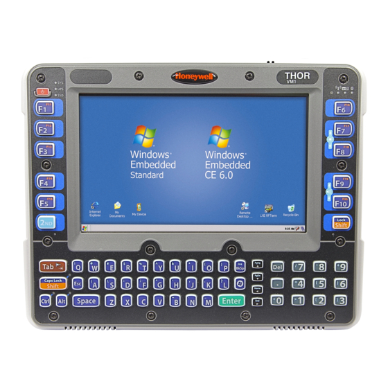
Components Front View 1. Power Button 2. Speakers 3. Ambient Light Sensor 4. Microphone... -
Page 18: Back View With Quick Mount Smart Dock
5. USB Connector (on Dock) 6. CAN/Audio Connector (on Dock) 7. Quick Release Handle (On Thor VM1) 8. Provision for Padlock (on Thor VM1 and Dock) 9. Provision for Laptop Security Cable (on Thor VM1) 10. Power Switch (on Dock) 11. -
Page 19: Chapter 2: Hardware
Chapter 2: Hardware System Hardware 802.11a/b/g Wireless Client The Thor VM1 has an 802.11a/b/g network card that supports diversity with two internal or external antennas. Power management for the network card is configured with the Summit Client Utility. Central Processing Unit The CPU is a 1.6MHz Intel Atom processor. -
Page 20: Input/Output Components
CompactFlash (CF) Slot The CF ATA slot is not hot swappable. The Thor VM1 must be powered down to insert or remove an ATA card. Since the operating system is stored on the CF ATA card, the Thor VM1 cannot operate without the ATA card. -
Page 21: Bluetooth Lxez Pairing
Bluetooth LXEZ Pairing The Thor VM1 contains Bluetooth version 2.0 with Enhanced Data Rate (EDR) up to 3.0 Mbit/s over the air. Bluetooth device connection (or pairing) can occur at distances up to 32.8 ft (10 meters) Line of Sight. The wireless client retains wireless connectivity while Bluetooth is active. -
Page 22: Power
If operating on UPS power and the UPS battery become critically low, the Thor VM1 performs a controlled shutdown. If there is no external power available, there must be 10% or greater power in the UPS battery or the Thor VM1 does not power... -
Page 23: Backup Battery
The backup battery should only be changed by authorized service personnel. Fuse The Thor VM1 uses a 10A time delay (slow blow), fuse that is externally accessible and user replaceable. The fuse is located on the back of the Quick Mount Smart Dock. -
Page 24: Power Modes
Off Mode The Thor VM1 is off when it is not connected to a power source and the UPS battery is depleted. However, an internal Real Time Clock (RTC) powered by an internal battery maintains the date and time while the Thor VM1 is off. When the Thor VM1 is... -
Page 25: Primary Events
USB data entry (from a USB keyboard or mouse) System Primary Events A System Primary Event allows the Thor VM1 to transition to D2 (System Idle) but the Thor VM1 does not enter D3 (Suspend) as long the system event occurs. -
Page 26: Power Configuration
If the Thor VM1 is Off, pressing the power button starts the power up sequence. Note: This assumes that the Thor VM1 is docked in a powered Quick Mount Smart Dock or that the internal UPS battery has a sufficient charge to power the Thor VM1. If no external power is available and the UPS battery does not have a charge, pressing the power button causes no action. -
Page 27: Vehicle Ignition Monitoring
If the Thor VM1 is Off and Ignition Input changes from Inactive to Active, the Thor VM1 boots. If the Thor VM1 is On and Ignition Input changes from Inactive to Active, the Thor VM1 remains On. If, for example, a Thor VM1 is running on the UPS and is placed into a Dock connected to a truck when the truck ignition is On, the power management scheme may change based on the availability of external power. -
Page 28: External Connectors
External Connectors Power the Thor VM1 off before attaching a cable to any port (serial, USB, Audio/CAN, etc.). Most external connectors for the Thor VM1 are located on the Quick Mount Smart Dock: COM1 connects to a serial bar code scanner, screen blanking cable, serial printer or PC. -
Page 29: Serial Connector (Com1 And Com2)
The COM1 and COM2 connectors are D-9 male connectors located on the back of the Quick Mount Smart Dock. Power the Thor VM1 off before attaching a cable to any port (serial, USB, Audio/CAN, etc.). The serial connectors are industry-standard RS-232, PC/AT standard 9–pin “D” male connector. -
Page 30: Screen Blanking
Screen Blanking Box. If using a switch: A cable from the Thor VM1 to the switch. The cable requires pin 7 (RTS – Request to Send Output) and pin 8 (Clear to Send Input) of a DB9 female connector to a switch that provides an electrical conductive connection on vehicle motion. -
Page 31: Sample Cable For Screen Blanking
The Screen Blanking Box is designed to monitor a connection to a vehicle motion sensing circuit. When motion is detected, the Screen Blanking Box opens the connection between the output feeds (which are connected to Pins 7 and 8 of the Thor VM1) and the display on the Thor VM1 is blanked. -
Page 32: Usb Connector
USB Connector The USB connector is a D-9 female connector located on the back of the Quick Mount Smart Dock. Power the Thor VM1 off before attaching a cable to any port (serial, USB, Audio/CAN, etc.). Signal Description Common ground... -
Page 33: Usb Dongle Cable
USB Dongle Cable 1. D9 Connector 2. USB Host Connector 3. USB Client Connector D9 Male Connector Signal Description Common ground USBC_D+ USB client data signal USBC_D- USB client data signal USB_H1_PWR USB host 5V output power Common ground Common ground USB_H1_D+ USB host 1 data signal USB_H1_D-... -
Page 34: Usb Host Connector
USB Host Connector Signal Description 5V_USB USB Power, Current Limited USB_H1_D- USB D- USB_H1_D+ USB D+ USB Power Return Shell CGND Chassis Ground USB Client Connector Signal Description 5V_USB USB Power, Current Limited USB_H1_D- USB D- USB_H1_D+ USB D+ USB Power Return Shell CGND Chassis Ground... -
Page 35: Power Supply Connector
Power Supply Connector Power is supplied to the Thor VM1 through the power connector. Additionally this assembly provides a connection point for the vehicle’s chassis ground to be connected internally to the conductive chassis of the computer. The Thor VM1 internal power supply can accept DC input voltages in the range of 10 to 60 Volts DC. -
Page 36: Canbus / Audio Connector
The CANbus/Audio connector is a D-15 male connector located on the back of the Quick Mount Smart Dock. The connector supports a headset adapter cable or a CANbus cable. The Thor VM1 does not support connecting audio and CANbus simultaneously. -
Page 37: Headset Adapter Cable
Headset Adapter Cable The headset cable attaches to the CANbus / Audio connector and provides a quick connect connection for a headset. D15 Female Connector Signal Description Not used Not used Not used Not used Not used Audio return Headset return Audio output Headset output Mic input... -
Page 38: Quick Connect Headset Connector
Quick Connect Headset Connector Signal Description Mic input Microphone input Mic return Microphone return Audio output Headset output Audio return Headset return 2-20... -
Page 39: Canbus Cable
CANbus Cable The CANbus interface is a virtual COM9 port. This port can be accessed using standard Windows API calls. D15 Female Connector Signal Description Not used CAN_L CAN_L bus line dominant low CAN_GND CAN ground CAN reserved Ground Not used Not used Not used Not used... -
Page 40: 9-Pin J1939 (Deutsch) Connectors
9-Pin J1939 (Deutsch) Connectors Receptacle Socket J1939 Female J1939 Male Signal Description CAN_GND CAN Ground CAN_V+ Option CAN external Power Supply CAN_H CAN_H bus line dominant high CAN_L CAN_L bus line dominant low CAN_SHLD Not used Not used Not used Not used 2-22... -
Page 41: Antenna Connections
Antenna Connections The Thor VM1 is equipped with an 802.11 radio and can be ordered with an internal antenna or external remote mount for antennas. When the Thor VM1 is ordered with internal antennas, the external antenna connectors are not used. GPS and WWAN are optional on the Thor VM1 and require external remote mount antennas. -
Page 42: Keyboard Options
64-key QWERTY Keyboard The Thor VM1 has a QWERTY keyboard, available with a standard overlay, an IBM 3270 overlay or an IBM 5250 overlay. Because the keyboard only has 64 keys, all functions are not visible (or printed on the keyboard). Therefore the Thor VM1 keyboard supports what is called hidden keys -- keys that are accessible but not visible on the keyboard. -
Page 43: Ibm 3270 Overlay
IBM 3270 Overlay 2-25... -
Page 44: Ibm 5250 Overlay
IBM 5250 Overlay 12-Key Keyboard The 12-key keyboard is available on the Thor VM1 running Windows CE 6.0. 2-26... - Page 45 Because the keyboard only has 12 keys, all functions are not visible (or printed on the keyboard). Therefore the Thor VM1 keyboard supports what is called hidden keys -- keys that are accessible but not visible on the keyboard. A key or combination of keys can be remapped to provide a single keypress, a string of keypresses or to execute an application or command.
-
Page 46: Keyboard Leds
Shift LEDs Note: The 64-key Thor VM1 has two Shift keys with an LED beside each key. The 12-key Thor VM1 has a single Shift key and LED. The Shift LEDs indicate the state of the keyboard Shift mode. If Shift is enabled the Shift LEDs beside both Shift keys (64-key only) blink green. -
Page 47: Led Functions
LED Functions System LEDs Connection LEDs 3. 2nd LED 4. Shift/CapsLock LED * 5. Ctrl LED * 6. Alt LED * 7. Shift/CapsLock LED * 64-key keyboards only System LEDs 1. SYS (System Status) LED 2. UPS (Uninterruptible Power Supply) 3. -
Page 48: Sys (System Status) Led
SYS (System Status) LED LED Behavior System State Solid Green On but Backlight Off On but Display Off Green blinking very slowly External power present Suspend (Approximately one half second on, 4.5 seconds off) External power not present Suspend Green blinking slowly External power present CPU temperature less than -20ºC, (Approximately one half second on, 1.5 seconds... -
Page 49: Ups Status Led
UPS Status LED The behavior of the UPS LED depends if external power is connected or not.. External Power Present LED Behavior Status No UPS charging, UPS charged Solid Green UPS charging Any charging fault, Out of charging temperature range, Solid Amber No UPS present, Charge timeout... -
Page 50: Connection Leds
Connection LEDs 1. WWAN LED 2. WiFi LED 3. Bluetooth LED WWAN LED LED Behavior Status Solid Green Indicates a WWAN connection to a network. Indicates no WWAN connection. WiFi LED LED Behavior Status Solid Amber Indicates a connection with an IP address to an Access Point Indicates no connection to an Access Point. -
Page 51: Keyboard Leds
Keyboard LEDs The keyboard LEDs are located near the specified key. 2nd LED LED Behavior Status Indicates the 2nd modifier key is active. 2nd mode is invoked for the next keypress only. Solid Green Pressing the 2nd key a second time exits this modifier mode and turns off the LED. 2nd mode is not invoked. -
Page 52: Alt Led
Alt LED The Alt key is not present on the 12-key keypad. LED Behavior Status Indicates the Alt modifier key is active. Alt mode is invoked for the next keypress only. Solid Green Pressing the Alt key a second time exits this modifier mode and turns off the LED. Alt mode is not invoked. -
Page 53: Display
Note: If the touch screen is disabled or looses calibration on a Thor VM1 with the 12 key keypad, you must use a USB mouse or keyboard attached to the Thor VM1 to access the control panel ro re-enable or recalibrate the touch screen. -
Page 54: Disconnect Ups Battery
1. For convenience, the Thor VM1 can be removed from the Quick Mount Vehicle Dock, though it is not necessary. 2. Place the Thor VM1 in Suspend. 3. Place the Thor VM1 face down on a stable surface. -
Page 55: Install Sd Card
4. Using a Phillips screwdriver (not supplied) loosen the screws and then remove the tethered access panel with the SSD and SD label. This panel is on the left hand side when the Thor VM1 is face down with the top away from the user. -
Page 56: Install Sim Card
4. Using a Phillips screwdriver (not supplied) loosen the screws and then remove the tethered access panel with the SIM label. This panel is on the right hand side when the Thor VM1 is face down with the top away from the user. -
Page 57: Field Replaceable Front Panel
The front panel of the Thor VM1 is field replaceable. The front panel assembly contains the keyboard, touchscreen and optional defroster. Should any of these components fail, the front panel assembly can easily be replaced to reduce downtime. The... - Page 58 5. Carefully lift the front panel away from the device. A. Slot on Thor VM1 body B. Wiring connector on Thor VM1 body 2-40...
- Page 59 6. Position the replacement front panel so the tab on the back of the front (D in figure above) panel lines up with the slot (A in figure above) on the Thor VM1. Be sure the two wiring connectors (B and C in figures above) are also aligned.
-
Page 60: Field Replaceable Ups Battery
Before replacing the Thor VM1 UPS battery, the internal UPS battery must be disconnected. The UPS battery in the Thor VM1 is field replaceable. Should the UPS battery fail, it can easily be replaced to minimize downtime. How To: Replace Front Panel 1. - Page 61 11. Place the UPS battery into the well. Note the orientation of the battery in the illustration below. The flat surface of the battery points toward the bottom of the Thor VM1. Make sure all wires are inside the battery well so they are not pinched when the front panel is reinstalled..
- Page 62 12. Position the front panel so the tab on the back of the front (D in figure above) panel lines up with the slot (A in figure above) on the Thor VM1. Be sure the two wiring connectors (B and C in figures above) are also aligned.
-
Page 63: Chapter 3: Software
The examples found in this section are to be used as examples only, the configuration of your specific Thor VM1 computer may vary. The following sections provide a general reference for the configuration of the Thor VM1 and some of its optional features. -
Page 64: General Windows Ce Keyboard Shortcuts
General Windows CE Keyboard Shortcuts Use the keyboard shortcuts in the chart below to navigate with the Thor VM1 keyboard. These are standard keyboard shortcuts for Windows CE applications. Press these keys … To … CTRL + C Copy CTRL + X... -
Page 65: Rebooting The Thor Vm1
Rebooting the Thor VM1 If a USB drive, such as a thumb drive is attached to the Thor VM1, the device attempts to boot from the USB drive: If the USB drive contains a bootable sector, the Thor VM1 boots from the USB drive. -
Page 66: Folders Copied At Startup
Executables in System\Startup must be the actual executable, not a shortcut, because shortcuts are not parsed by Launch. Saving Changes to the Registry The Thor VM1 saves the registry when you: Warmboot - either from the Registry control panel, the warmboot command or the reboot keypress sequence. -
Page 67: Software Load
Note that the viewer applications allow viewing documents, but not editing them. ActiveSync ActiveSync is pre-loaded on mobile devices. Using Microsoft ActiveSync you can copy files from your Thor VM1 to your desktop/laptop , and vice versa. After an ActiveSync relationship (partnership) has been established with a desktop/laptop, ActiveSync will automatically startup each time the Thor VM1 is cabled to the desktop/laptop. -
Page 68: Rfterm (Optional)
The application can also be accessed by double-clicking the RFTerm desktop icon. Avalanche The Wavelink Avalanche Enabler installation file is loaded on the Thor VM1; however, the device is not configured to launch the installation file automatically. The installation application must be run manually the first time Avalanche is used. Following installation, the Wavelink Avalanche Enabler will be an auto-launch application. -
Page 69: Thor Vm1 Utilities
Order is used to force a sequence of events. Order=0 is first, and Order=99 is last. Order must be greater than 4 for the Thor VM1. Two items which have the same order will be installed in the same pass, but not in a predictable sequence. - Page 70 If the Installed flag is set, auto-launch looks for the FileCheck file. If it is present, the CAB file is installed, and that registry entry is complete. If the FileCheck file is not present, memory has been lost, and the utility calls WCELOAD to reinstall the CAB file.
-
Page 71: Launch.exe And Persistent Storage
Registry control panel. This is the preferred method for saving a backup of the registry. Save the registry file to the System folder on the Thor VM1 (persistent storage) or copy the file to a PC. WARMBOOT.EXE Double-click this file to warm boot the computer (i.e., all RAM is preserved). It automatically saves the registry before rebooting which means configuration changes are not lost. -
Page 72: Prtscrn.exe
PrtScrn.EXE Command line utility which performs a screen print and saves the file in .BMP format in the \System folder. Tap Start > Run and type prtscrn and tap OK, or press Enter. There is a 10 second delay before the screen print is made. The device beeps and the screen captured file (scrnnnnn.bmp) is placed in the \System folder. -
Page 73: Desktop
Windows on-line Help application installed in the mobile device. The Thor VM1 Desktop appearance is similar to that of a desktop PC running a Windows operating system. At the bottom of the screen is the Start button. Tapping the Start Button causes the Start Menu to pop up. -
Page 74: Taskbar
Start button. Access programs, select from the Favorites listing, documents last worked on, change/view set- tings for the control panel or taskbar, on-line help or run programs. Taskbar The number and type of icons displayed are based on the device type, installed options and configuration of the Thor VM1. 3-12... -
Page 75: My Device Folders
Related Manual: Using Wavelink Avalanche The Thor VM1 has the Avalanche Enabler installation files loaded, but not installed, on the mobile device when it is shipped The installation files are located in the System folder on CE devices. The installation application must be run manually the first time Avalanche is used. -
Page 76: Start Menu Program Options
If installed and pre-configured, Wavelink Avalanche connects remotely and downloads updates automatically during each reboot. Communication Start > Programs > Communication ActiveSync ActiveSync is pre-loaded on the Thor VM1. Using Microsoft ActiveSync you can copy files from your Thor VM1 to your desktop computer , and vice versa. 3-14... -
Page 77: Connect And Lxeconnect
USB on the Thor VM1. Connect and LXEConnect Upon cabling your Thor VM1 to the desktop/laptop, and ActiveSync on the desktop/laptop opens, if the Connect or LXEConnect installation does not open on your host PC, Contact your representative for assistance. -
Page 78: Express Scan
The eXpress Scan utility allows an administrator to scan bar codes to provide the initial network and Avalanche Mobile Device Server address configuration. This eliminates the need to edit radio parameters manually on the Thor VM1. eXpress Scan uses bar codes created with eXpress Config. -
Page 79: Settings
Microsoft Remote Desktop options. If installed, Remote Desktop on the Thor VM1 can be accessed by Start > Programs > Remote Desktop. Select a computer from the drop down list or enter a host name and tap the Connect button. -
Page 80: Advanced Tab
Refer to Start > Help for an explanation of standard Windows CE taskbar icons. Following are a few of the unique Thor VM1 taskbar icons that may appear in the Taskbar. These icons are in addition to the Windows CE taskbar icons. - Page 81 Summit Client signal indicator no signal/ excellent signal. Clicking on the icon opens the Summit Client Utility. Gobi Connection Manager (WWAN) signal indicator no signal / excellent signal. Clicking on the icon opens the Gobi Connection Manager. UPS battery charge indicator. Percent of battery charge is indicated. External power connected / connected and UPS battery charging.
-
Page 82: Thor Vm1 Os Upgrade
Maintain an uninterrupted AC/DC power source to the Thor VM1 throughout this process. The CF card with the OS and systems files must be present for the Thor VM1 to boot. Removal or installation of SD or CF cards should be performed on a clean, well-lit surface. -
Page 83: Bios
The second device is the Windows CE Image. If a USB drive, such as a thumb drive is attached to the Thor VM1, the device attempts to boot from the USB drive: If the USB drive contains a bootable sector, the Thor VM1 boots from the USB drive. -
Page 84: Control Panel
Control Panel Start > Settings > Control Panel or My Device > Control Panel link Tap the ? button for Help when changing Thor VM1 Control Panel options. Option Function About Software, hardware, versions and network IP. No user intervention allowed. - Page 85 Set appearance of numbers, currency, time and date based on country region and Regional Settings language settings. Registry Choose options for managing the registry and rebooting the Thor VM1. Remove Programs Select to remove specific user installed programs in their entirety. Screen Control Configure screen blanking and automatic screen brightness control.
-
Page 86: About
About Start > Settings > Control Panel > About The data cannot be edited by the Thor VM1 user on these panels. Contents GUID, Serial Number, Windows CE Version, OAL Version, Compile Version, and Software Language. Language indicates localized version. -
Page 87: Identifying Software Versions
The Versions tab displays the versions of many of the software programs installed. Not all installed software is included in this list and the list varies depending on the applications loaded on the Thor VM1. The Image line displays the revision of the system software installed. -
Page 88: Accessibility
Accessibility Start > Settings > Control Panel > Accessibility Customize the way the Thor VM1 keyboard, sound, display, mouse, automatic reset and notification sounds function. There are a few changes from general Windows desktop Accessibility options. Sticky Keys - Disabled (cannot be enabled). -
Page 89: Administration (For Applock)
AppLock is designed to be run on certain certified Windows CE based devices only. The AppLock program is installed as part of the default software load. Configuration parameters are specified by the AppLock Administrator for the Thor VM1 end-user. AppLock is password protected by the Administrator. -
Page 90: Factory Default Settings - Applock
Factory Default Settings - AppLock Application Panel Filename Blank Title Blank Arguments Blank Order Internet Disabled Global Key Ctrl+Spc Global Delay 10 sec Input Panel Disabled Launch Button Panel Auto at Boot Enabled Auto at Boot Retries Auto at Boot Delay 10 sec Auto Re-launch Enabled... -
Page 91: Setup A New Device
Setup a New Device Devices with the AppLock feature are shipped to boot in Administration mode with no default password, thus when the Thor VM1 is first booted, the user has full access to the device and no password prompt is displayed. After the administrator specifies the applications to lock, a password is assigned and the device is rebooted or the hotkey is pressed, the device switches to end-user mode. -
Page 92: End User Mode
End User Mode End-user mode locks the end-user into the configured application or applications. The end user can still reboot and respond to dialog boxes. Each application is automatically launched and runs in full screen mode when the device boots up. The user cannot unintentionally or intentionally exit the application nor can the end user execute any other applications. -
Page 93: End-User Switching Technique
A checkmark indicates applications currently active or available for Launching by the user. When Keyboard is selected, the Thor VM1 default input method (Input Panel, Transcriber, or custom input method) is activated. The check to the left of the application name indicates that the application is active. -
Page 94: Hotkey (Activation Hotkey)
Hotkey (Activation hotkey) The default Hotkey (Activation key) is Ctrl+Spc. The key sequence switches the focus between one application and another. Data entry affects the application running in the foreground only. Note that the system administrator may have assigned a different key sequence to use when switching applications. -
Page 95: Application Configuration
Application Configuration Settings > Control Panel > Administration icon The default Administrator Hotkey sequence is Shift+Ctrl+A. Administrator mode allows access to all features on the device. When the hotkey is pressed to switch into Administrator mode, a password prompt is displayed (if a password has been configured). A password must be entered within 30 seconds (and within three tries) or the password prompt is removed and the device remains in end-user mode with the focus returned to the locked application. -
Page 96: Application Panel
Application Panel Use the Application tab options to select the applications to launch when the device boots up in End-user Mode. If no application is specified when the Administrator Control Panel is closed, the mobile device reboots into Administrator mode. If a password has been set, but an application has not been specified, the user will be prompted for the password before entering administration mode. - Page 97 Option Explanation Default is Disabled. Enable (check) to show the Keyboard option on the Switchpad menu. When Input Panel enabled the input panel cannot be enabled or disabled for each individual application, and is avail- able to the user for all configured applications. Tap the Clear button to clear all currently displayed Filename or Application information.
-
Page 98: Launch Button
Launch Button Note: The Launch button may not be available in all versions of Multi-AppLock. Contact your representative for assistance, downloads and AppLock update availability. When clicked, displays the Launch options panel for the Filename selected on the Administration panel. Note: Launch order is determined by the Order specified in the Application tab. -
Page 99: Auto At Boot
Auto At Boot Default is Enabled. Auto At Boot When enabled, automatically launches (subject to the specified Delay in seconds) the application after the unit is rebooted. If a Delay in seconds is specified, AppLock waits for the specified period of time to expire before launching the application. The Delay default value is 10 seconds;... -
Page 100: Auto Re-Launch
Auto Re-Launch Auto Re-Launch Default is Enabled. When enabled for a specific application, automatically re-launches it (subject to the specified Auto Re-Launch Delay in seconds) after it terminates. This option allows the Administrator to disable the re-launch operation. AppLock cannot prevent all applications from closing. -
Page 101: Manual (Launch)
Manual (Launch) Default is Disabled. Enabling this option allows the end-user to launch the specified application(s). Upon bootup completion an application with Manual enabled is listed on the Switchpad accompanied by a checkmark that indicates the application is currently active or available for Launching. When an application name is tapped by the end-user, the application is launched (if inactive) and brought to the foreground. -
Page 102: End User Internet Explorer (Euie)
End User Internet Explorer (EUIE) AppLock supports applications that utilize Internet Explorer, such as .HTML pages and JAVA applications. The end user can run an application by entering the application name and path in Internet Explorer’s address bar. To prevent the end user from executing an application using this method, the address bar and Options settings dialog are restricted in Internet Explorer. -
Page 103: Security Panel
Security Panel Hotkey Specify the hotkey sequence that triggers AppLock to switch between administrator and user modes and the password required to enter Administrator mode. The default hotkey sequence is Shift+Ctrl+A. key keypress is an invalid keypress for a hotkey sequence. Move the cursor to the Hot Key text box. -
Page 104: Options Panel
Options Panel AppLock contains several types of delays and timeouts to accommodate different applications. Please note that the delays specified on the Launch panel are delays before AppLock attempts to start the specified application(s). The timeouts specified on this panel are delays after AppLock has attempted to launch the application. Launch timeout This timeout specifies the period of time for AppLock to wait for the application to initially launch after the application has been called. -
Page 105: Status Panel
Status Panel Use the Status panel to view the log of previous AppLock operations and to configure which messages are to be recorded during AppLock operation. Status information is stored in a specific location on the storage device and in a specific logfile specified by the Administrator. For this reason, the administrator can configure the type of status information that is logged, as well as clear the status information. -
Page 106: Log
Note: If a level higher than Error is selected, the status should be cleared frequently by the administrator. In addition to the three view levels the administrator can select that all status information be logged or turn off all status information logging completely. -
Page 107: Applock Help
AppLock Help The mobile device won’t switch from Administration mode to end-user mode. If the configuration is valid for one application but not the other, the switch to end-user mode fails. AppLock stays in Administration mode and is stopped until the Administrator password is entered. The hotkey sequence needed is not allowed. -
Page 108: Applock Error Messages
AppLock Error Messages Any messages whose first word is an ‘ing’ word is output prior to the action described in the message. For example, “Switching to admin-hotkey press” is logged after the administrator has pressed the hotkey but prior to starting the switch process. For all operations that can result in an error, an Error level message is displayed when a failure occurs. - Page 109 Message Explanation and/or corrective action Level The load of the keyboard filter failed. This occurs when the dll is missing or is corrupted. Look in the \Windows directory for kbdhook.dll. If it exists, delete it. Also delete Cannot find kbdhook.dll LOG_ERROR AppLock.exe from the \Windows directory and reboot the unit.
- Page 110 Message Explanation and/or corrective action Level Encrypt failure The password encryption failed. LOG_ERROR Encrypt gen key failure Unable to encrypt password. LOG_ERROR Encrypt generate key fail- Unable to encrypt password. LOG_ERROR Encrypt get user key fail- Unable to encrypt password. LOG_ERROR Encrypt get user key ok Encrypt password process successful.
- Page 111 Message Explanation and/or corrective action Level Exit AppLock- There are two exit paths from the enumeration function. This message denotes the enu- LOG_PROC- EnumWindows-Not meration function did not find the application. ESSING found LOG_PROC- Exit DecryptPwd Exiting password decryption processing. ESSING LOG_PROC- Exit EncryptPwd...
- Page 112 Message Explanation and/or corrective action Level Hook wndproc of open The application is open, but AppLock cannot lock it. LOG_ERROR app failure Hot key event creation The Admin applet is unable to create the hotkey notification. LOG_ERROR failure Hot key pressed Processing the hotkey and backdoor entry LOG_EX Hot key pressed...
- Page 113 Message Explanation and/or corrective action Level Registering Backdoor The AppLock system communicates with the keyboard hook via a user defined message. LOG_PROC- Both AppLock.exe and Kbdhook.dll register the message at initialization. ESSING The AppLock system communicates with the keyboard hook via a user defined message. LOG_PROC- Registering Hotkey MSG Both Applock.exe and Kbdhook.dll register the message at initialization.
- Page 114 Message Explanation and/or corrective action Level After the application is launched, AppLock must wait until the application has initialized Timeout looking for app itself before proceeding. The application did not start successfully and AppLock has timed LOG_ERROR window out. ToUser after admin, not The user mode switch is attempted when the device boots and after the administrator LOG_EX at boot...
-
Page 115: Battery
Start > Settings > Control Panel > Battery This panel is used to view the status and percentage of power remaining in the Thor VM1 UPS battery. The battery gas gauge icon resides in the system tray and shows four levels of charge – 100%, 75%, 50%, 25%. -
Page 116: Bluetooth
Bluetooth Start > Settings > Control Panel > Bluetooth Note: Contact your representative for upgrade availability if your Bluetooth control panel is not the same as the control panels presented in this section. Discover and manage pairing with nearby Bluetooth devices. Factory Default Settings Discovered Devices None... -
Page 117: Bluetooth Devices
It is not necessary to disconnect a paired scanner and printer before a different scanner or printer is paired with the Thor VM1. The target Bluetooth device should be as close as possible (up to 32.8 ft (10 meters) Line of Sight) to the Thor VM1 during the pairing process. -
Page 118: Stop Button
Note: When an active paired device enters Suspend Mode, is turned Off or leaves the Thor VM1 Bluetooth scanning range, the Bluetooth connection between the paired device and the Thor VM1 is lost. There may be audible or visual signals as paired devices disconnect from the Thor VM1. -
Page 119: Clear Button
An icon with a white background indicates the device is connected to the Thor VM1 and the device's Bluetooth connection is active. Double-tap a device in the list to open the device properties menu. The target device does not need to be active. -
Page 120: Bluetooth Device Menu
Stop the connection between the Thor VM1 and the highlighted paired Bluetooth device. Remove an unpaired device from the Bluetooth device list. The highlighted device name and iden- Delete tifier is removed from the Thor VM1 Bluetooth Devices panel after the user taps OK. Properties More information on the highlighted Bluetooth device. -
Page 121: Bluetooth Device Properties
Bluetooth Device Properties Data on the Bluetooth Properties panel cannot be changed by the user. The data displayed is the result of the device Query performed during the Discovery process. The Status dialog box reflects the current state of the highlighted device. 3-59... -
Page 122: Settings
Settings Note: These options can still be checked or unchecked whether Bluetooth connection is enabled or disabled. Turn Off Bluetooth Tap the button to toggle the Bluetooth client On or Off. The button title changes from Turn Off Bluetooth to Turn On Bluetooth. Default The default value is Bluetooth On. -
Page 123: Options
Enable this option to ensure other devices can discover the Thor VM1. This option is Enabled by default. A dialog box appears on the Thor VM1 screen notifying the user a Bluetooth device requests to pair with the Thor VM1. -
Page 124: Reconnect
Reconnect Note: These options can still be checked or unchecked whether Bluetooth connection is enabled or disabled. 3-62... -
Page 125: Options
Options Option Function This option is Enabled (checked) by default. There may be an audio or visual signal when a connection between a paired, active device is Report when connection lost. lost A visual signal may be a dialog box placed on the display notifying the user the connection between one (or all) of the paired Bluetooth devices has stopped. - Page 126 Option Function This option is Enabled (checked) by default. This option controls the overall mobile Bluetooth device reconnect behavior. When Auto Reconnect is disabled (unchecked), Auto Reconnect on Boot is automatically disabled and dimmed. When Auto Reconnect is disabled (unchecked), no devices are reconnected in any situation.
-
Page 127: About
About This panel lists the assigned Computer Friendly Name (that other devices may discover during their Discovery and Query process), the Bluetooth MAC address, and software version levels. The data cannot be edited by the user. 3-65... -
Page 128: Using Bluetooth
2. Tap the Settings Tab. 3. Change the Computer Friendly Name at the bottom of the Settings display. The Bluetooth Thor VM1 default name is determined by the factory installed software version. A unique name (up to 32 characters) should be assigned to every Thor VM1 before Bluetooth Discovery is initiated. -
Page 129: Subsequent Use
LED on the device, or a dialog box is placed on the Thor VM1 display. 11. Whenever the Thor VM1 is turned On, all previously paired, live, Bluetooth devices in the vicinity are paired, one at a time, with the Thor VM1. -
Page 130: Bluetooth Indicators
Thor VM1 is out of range of all paired Bluetooth device(s). Connection is inactive. Note: When an active paired device enters Suspend Mode, is turned Off or leaves the Thor VM1 Bluetooth scan range, the Bluetooth connection between the paired device and the Thor VM1 is lost. There may be audible or visual signals as paired devices disconnect from the Thor VM1. -
Page 131: Bluetooth Bar Code Reader Setup
To open the LXEZ Pairing program, tap Start > Settings > Control Panel > Bluetooth or tap the Bluetooth icon on the desktop or tap the Bluetooth icon in the taskbar. Locate the bar code label, similar to the one shown above, attached to the Thor VM1. The label is the Bluetooth address identifier for the Thor VM1. -
Page 132: Thor Vm1 Without Label
Thor VM1 without Label If the Thor VM1 Bluetooth address bar code label does not exist, follow these steps to create a unique Bluetooth address bar code for the Thor VM1: First, locate the Thor VM1 Bluetooth address by tapping Start > Settings > Control Panel > Bluetooth > About tab. -
Page 133: Bluetooth Beep And Led Indications
Bluetooth Printer Setup The Bluetooth managed device should be as close as possible, in direct line of sight, with the Thor VM1 during the pairing process. 1. Open the LXEZ Pairing Panel. 2. Tap Discover. Locate the Bluetooth printer in the Discovery panel. -
Page 134: Easy Pairing And Auto-Reconnect
Setup the Bluetooth module to establish how the user is notified by easy pairing and auto-reconnect events. AppLock, if installed, does not stop the end-user from using the Bluetooth application, nor does it stop other Bluetooth-enabled devices from pairing with the Thor VM1 while AppLock is in control. 3-72... -
Page 135: Certificates
Manage digital certificates used for secure communication. Note: Digital certificates are date sensitive. If the date on the Thor VM1 is incorrect, wireless authentication will fail. The Certificates stores lists the certificates trusted by the Thor VM1 mobile device user. -
Page 136: Data Collection Wedge Introduction
This software component is the interface between data collection devices such as bar code scanners, or imagers, externally connected to a COM port on the Thor VM1 or bar code scanners wirelessly connected via Bluetooth to your Thor VM1. This software component collects the data from the varied sources and presents it to applications on your Thor VM1 in a transparent manner. -
Page 137: Bar Code Readers
Bar Code Readers The Thor VM1 can use the following external bar code readers: Tethered hand-held scanners are tethered to a serial port on the Thor VM1 and are configured by scanning the engine- specific bar codes in the scanner manufacturer's programming guide. The manufacturer's guides are usually shipped with the bar code reader. -
Page 138: Data Processing Overview
Data Processing Overview Bar code data processing involves several steps. Some steps may be skipped during the processing depending on user selections on the Data Options control panels. The steps are presented below in the order they are performed on the scanned data. -
Page 139: Factory Default Settings
Factory Default Settings Main Tab Device 1 Disabled Device 2 Disabled Device 3 Disabled Send Key Message (WEDGE) Enabled COM1 Tab (External serial port) Baud Rate 9600 Stop Bits Parity None Data Bits Power on Pin 9 Enabled COM2 Tab (External serial port) Baud Rate 9600... -
Page 140: Main Tab
Main Tab Start > Settings > Control Panel > Data Collection > Main tab The parameters shown on these panels are only those that apply to the specific mobile device. Parameter Function 1 - Default is Disabled 2 - Default is Disabled Device 1,2,3 3 - Default is Disabled The data collection device (laser scanner, laser imager, external, or wireless). -
Page 141: Com1 Tab
COM1 Tab Start > Settings > Control Panel > Data Collection > COM1 This panel sets communication parameters for any device connected to the external port. Adjust the settings and click the OK button to save the changes. Any changes take effect immediately. This panel does not configure the connected device. -
Page 142: Com2 Tab
COM2 Tab Start > Settings > Control Panel > Data Collection > COM2 This panel sets communication parameters for any device connected to the external port. Adjust the settings and click the OK button to save the changes. Any changes take effect immediately. This panel does not configure the connected device. -
Page 143: Data Options Tab
Start > Settings > Control Panel >Data Collection > Data Options tab Bar code manipulation parameter settings on this tab are applied to the incoming data resulting from successful bar code scans sent to the Thor VM1 for processing. Note: The Data Options tab contains only those options available for one type of decoding engine. -
Page 144: Buttons
Buttons Individually enable or disable a bar code from being scanned, set the mini- mum and maximum size bar code to accept, strip Code ID, strip data from Symbology Settings the beginning or end of a bar code, or (based on configurable Bar Code Data) add a prefix or suffix to a bar code before transmission. -
Page 145: Data Options - Symbology Settings
Data Options - Symbology Settings Start > Settings > Control Panel > Data Collection > Data Options > Symbology Settings button The Symbology selected in the Symbology drop-down list defines the symbology for which the data is being configured. The features available on the Symbology panel include the ability to individually enable or disable a bar code from scanning, set the minimum and maximum size bar code to accept,... -
Page 146: Clear Button
When All is selected in the Symbology field and the settings are changed, the settings in this dialog become the defaults, used unless overwritten by the settings for individual symbologies. This is also true for Custom IDs, where the code IDs to be stripped are specified by the user. -
Page 147: Enable, Min, Max
Enable, Min, Max Enable This checkbox enables (checked) or disables (unchecked) the symbology field. The scanner driver searches the beginning of the bar code data for the type of ID specified in the Data Options tab -- Enable Code ID field plus any custom identifiers. When a code ID match is found as the scanner driver processes incoming bar code data, if the symbology is disabled, the bar code is rejected. -
Page 148: Strip Leading/Trailing Control
Strip Leading/Trailing Control Start > Settings > Control Panel > Data Collection > Data Options tab > Symbology button This group of controls determines what data is removed from the collected data before the data is buffered for the application. When all values are set, Code ID takes precedence over Leading and Trailing;... -
Page 149: Bar Code Data Match List
Bar Code Data Match List Bar Code Data Panel This panel is used to strip data that matches the entry in the Match list from the bar code. Enter the data to be stripped in the text box and tap the Insert or Add button. The entry is added to the Match list. To remove an entry from the Match list, highlight the entry in the list and click the Remove button. -
Page 150: Match List Rules
Prefix and Suffix data is always added on after stripping is complete, and is not affected by any stripping settings. If the stripping configuration results in a 0 length bar code, a good beep will still be emitted, since bar code data was read from the scanner. -
Page 151: Add Prefix/Suffix Control
Note: Non-ASCII equivalent keys in Key Message mode are unavailable in this option. Non-ASCII equivalent keys include the function keys (e.g. F1), arrow keys, Page up, Page down, Home, and End. Symbologies The Thor VM1 supports only Custom IDs. 3-89... -
Page 152: Ctrl Char Mapping
Ctrl Char Mapping The Ctrl Char Mapping button (Control Character Mapping) activates a dialog to define the operations the Data Collection Wedge performs on control characters (values less than 0x20) embedded in bar codes. Control characters can be replaced with user-defined text which can include hat encoded or hex encoded values. In key message mode, control characters can also be translated to their control code equivalent key sequences. -
Page 153: Character
Character This is a drop down combo box that contains the control character name. Refer to the Character drop down box for the list of control characters and their names. When a character name is selected from the drop down box, the default text Ignore (drop) is shown and highlighted in the Replacement edit control. -
Page 154: Custom Identifiers
Custom Identifiers Code IDs are defined by the user for external bar code scanners. These are called custom Code IDs and are included in the Symbology drop down box in the Symbology dialog, unless Enable Code ID is set to None. When the custom Code ID is found in a bar code, the configuration specified for the custom Code ID is applied to the bar code data. -
Page 155: Buttons
Buttons Entering data into both the Name and ID Code fields enables the Add button. Click the Add button and the data is added to the next empty location in the Custom ID list. Insert Click on an empty line in the Custom ID list. The Add button changes to Insert. Enter data into both the Name and ID Code fields and click the Insert button. -
Page 156: Control Code Replacement Examples
Control Code Replacement Examples Configuration Example Con- Example Con- Translation Translated Data Data trol Character figuration The control character is discarded from 0x1B in the bar code is dis- Ignore (drop) ESCape Ignore (drop) the bar code data, prefix and suffix carded. -
Page 157: Bar Code Processing Examples
Bar Code Processing Examples The following table shows examples of stripping and prefix/suffix configurations. Symbology EAN-128(]C1) EAN-13(]E0) Intrlv 2 of 5(]IO) Code93 Enable Enabled Enabled Enabled Enabled Disabled Min length Max length Strip Code ID Enabled Enabled Disabled Enabled Strip Leading Strip Bar Code Data *123 Strip Trailing... -
Page 158: Processing Tab
Processing Tab Start > Settings > Control Panel > Data Collection > Processing tab The Processing tab contains a user configurable key delay that applies to scanned bar codes as they are input when Remote Desktop is the application with the input focus. Factory Default Settings Enable buffered key output Enabled... -
Page 159: About Tab
Start > Settings > Control Panel > Data Collection > About tab This tab displays the Data Collection Wedge driver version installed in the Thor VM1. The version number shown in the image below is used only as an example, your version number will be different. -
Page 160: Length Based Bar Code Stripping
Length Based Bar Code Stripping Use this procedure to create symbology rules for two bar codes with the same symbology but with different discrete lengths. This procedure is not applicable for bar codes with variable lengths (falling between a maximum value and a minimum value). Example: For the purposes of this example, the following sample bar code parameters will be used –... - Page 161 Click the Bar Code Data button. Click the Add button. Add the data for the match codes. Refer to the previous section Bar Code Data Match List for instruction. Scan a bar code and examine the result. 3-99...
-
Page 162: Hat Encoding
Hat Encoding 3-100... - Page 163 3-101...
-
Page 164: Date / Time
Date / Time Start > Settings > Control Panel > Date/Time - or - Time in Desktop Taskbar Use this Thor VM1 panel to set Date, Time, Time Zone, and assign a Daylight Savings location. Factory Default Settings Current Time... -
Page 165: Dialing
Dialing Start > Settings > Control Panel > Dialing Set dialup properties for internal modems (not supplied or supported on the Thor VM1). Factory Default Settings Location Work Area Code Tone Dialing Enabled Country/Region Disable Call Waiting Disabled (blank) 3-103... -
Page 166: Display
The display might also called the touchscreen. Select the desktop background image and appearance scheme for the Thor VM1. Using the options on the Backlight tab, set the display backlight and keypad backlight timers when running on battery or external power. -
Page 167: Appearance
Appearance There is very little change from general desktop PC Appearance options. Select a scheme from the dropdown list and make changes to the parameters. The default is High Contrast White for monochrome displays and Windows Standard for color displays. Tap the Save button to save any changes, renaming the scheme if desired. Tap the Delete button to delete schemes. Tap the Apply button to apply the selected scheme to the display. -
Page 168: Gobi Connection Manager
4. Use a Phillips screwdriver (not supplied) loosen the screws and then remove the tethered access panel with the SIM label. This panel is on the right hand side when the Thor VM1 is face down with the top away from the user. -
Page 169: Activate
7. Reinstall the Thor VM1 in the Dock. 8. Resume the Thor VM1 from suspend. Activate To activate service for a CDMA carrier such as Verizon, complete the necessary entries on the Activate tab. 3-107... -
Page 170: Home
The status of the Gobi 2000 radio is displayed in the lower left corner of this tab. An error message is displayed in this location if the firmware selected requires a SIM card and no SIM card is installed in the Thor VM1. -
Page 171: Cdma
CDMA Use the CDMA tab to activate the Thor VM1 for use with a CDMA carrier such as Verizon. This step is not necessary for carriers using a SIM card. The Serial Number, IMEI (International Mobile Equipment Identity) and MEID (Mobile Equipment ID) numbers are displayed on this tab as the carrier may request this information when setting up an account. -
Page 172: Autoconnect
4. Tap Activate. 5. Verify the activation process is successful by reviewing the message below the Activation Type group. Autoconnect When checked, Autoconnect is enabled. The Connection Manager automatically connect when necessary, such as when Internet Explorer is launched. Data Connection Test Tap the Connect button to make a temporary test connection to validate the carrier account. -
Page 173: Utms
UTMS Use the UTMS tab to configure the session parameters. Autoconnect When checked, Autoconnect is enabled. The Connection Manager automatically connect when necessary, such as when Internet Explorer is launched. Data Connection Test Tap the Connect button to make a temporary test connection to validate the carrier account. Entries identified with an asterisk (*) are used to configure the test connection. -
Page 174: Gps
This tab displays the information available from the GPS built into the Gobi radio. Tap the Start button to initiate a scan for GPS data. The information on this tab is updated every 3 seconds. Tap the Reset All Data button to clear all GPS data from the Gobi radio. You must confirm that you want to rest the data. Use this button with caution as it takes a longer time for the GPS to establish a valid fix after the data is cleared. -
Page 175: About
About This tab displays information on the Gobi 2000 radio installed in the Thor VM1. 3-113... -
Page 176: Input Panel
Input Panel Start > Settings > Control Panel > Input Panel Set the current Thor VM1 keys and data input method. Factory Default Settings Input Panel tab Input Method Keyboard Allow applications to change Enabled input panel state Options button... -
Page 177: Internet Options
Start > Settings > Control Panel > Internet Options Set options for Thor VM1 Internet connectivity. Select a tab. Tap the ? button for help using Windows CE Help installed in your mobile device. Adjust the settings and tap the OK button. - Page 178 Note: Security Tab: Use the Settings button to set ActiveX control, scripting and plug-in behavior for each zone (Internet, Local intranet, Trusted Sites, Restricted Sites). Use the Site button to add sites to each zone. 3-116...
- Page 179 3-117...
-
Page 180: Keyboard
Keyboard Start > Settings > Control Panel > Keyboard Set keypad key map, keypad key repeat delay, and key repeat rate. Factory Default Settings Repeat character Enable Repeat Delay Short Repeat Rate Slow 3-118... -
Page 181: Keypad
KeyPad Start > Settings > Control Panel > KeyPad Icon Use this control panel option to assign key functions to mappable keys available on your Thor VM1, determine application launch sequences and program command Run sequences. Factory Default Settings KeyMap... -
Page 182: Keymap Tab
If 2nd + F5 is remapped to another key, pressing 2nd + F5 generates the remapped key. However, if the next keypress is Shift, the Thor VM1 reboots. The remapped keypress DOES NOT affect the 2nd + F5 + Shift reboot key sequence. -
Page 183: How To Remap An Application
How to Remap an Application 1. Select the modifier key from the Modifier Mode options. 2. Select the key to be remapped from the Key pulldown list. 3. Select Launch App1-4 from the remapped key from the Remapped Key pulldown list. 4. -
Page 184: Launchapp Tab
The default for all text boxes is Null or “ ”. The text boxes accept string values only. Note that executables and parameters are not checked for accuracy by the keyboard driver. If the launch fails, the Thor VM1 emits a single beep, if the launch is successful, it is silent. -
Page 185: Runcmd Tab
The default for all text boxes is Empty, Null or " ". The text boxes accept string values only. Note that executables and parameters are not checked for accuracy by the keyboard driver. If the launch fails, the Thor VM1 emits a single beep, if the launch is successful, the mobile device is silent. -
Page 186: License Viewer
License Viewer Start > Settings > Control Panel > License Viewer Use this option to view software license registration details, and service contract length for a Thor VM1. Information on the License Viewer tabs is unique for each Thor VM1. -
Page 187: Mixer
Mixer Start > Settings > Control Panel > Mixer The Thor VM1 has two speakers (located at the bottom front of the unit). They are active when a headset is not connected to the device. Use the settings on these panels to adjust the master volume and record gain and sidetone for microphone input. -
Page 188: Input Panel
Input Panel Tap the OK button to save changes and exit the control panel. Changes are saved across the Properties tabs. A message may be displayed that a warm boot is necessary otherwise changes are in effect immediately. Tap the X button to ignore the current properties changes and exit the control panel. Tap the ? button for help. -
Page 189: Mouse
Mouse Start > Settings > Control Panel > Mouse Use this option to set the double-tap sensitivity for stylus taps on the Thor VM1 touchscreen. 3-127... -
Page 190: Network And Dialup Options
Network and Dialup Options Start > Settings > Control Panel > Network and Dialup Connections Set Thor VM1 network driver properties and network access properties. Select a connection to use, or create a new connection. Create a New Connection 1. On the mobile device, select Start > Settings > Control Panel > Network and Dialup Connections. A window is displayed showing the existing connections. -
Page 191: Network Capture
Network Capture Start > Settings > Control Panel > Network Capture Note: Verify the date and time before using the logging utilities to ensure meaningful data. The Network Capture panels provide configuration options for logging utilities. Two types of logging are configurable: Netlog is a Windows CE utility that monitors network traffic. -
Page 192: Netlog
Netlog Use this control panel to configure the Netlog utility. By configuring Netlog using the control panel, Netlog remains running across a warmboot. However, please note that: Netlog first stores data to a file named netlog0.cap, then netlog1.cap. Any time the current file reaches maximum size, Netlog switches to the other file. -
Page 193: Ndislog
Run cmd Performs the command selected. For example, to run Netlog and modify the packet size do the following: Select load from the Commands list and click the Run cmd button. Select stop from the Commands list and click the Run cmd button. Select options from the Commands list, enter the new packet size in the Options list and click the Run cmd button. -
Page 194: Options
Options Start > Settings > Control Panel > Options It may be necessary to warmboot the Thor VM1 after making desired changes. A pop up window indicates if a warmboot is required. Note: If there is no icon corresponding to this item in the Control Panel, contact your Contact your representative for upgrade details. -
Page 195: Communication
.RDP file will not persist across a warmboot. Autolaunch TimeSync By default, TimeSync does not automatically run on the Thor VM1. To enable TimeSync to run automatically on the Thor VM1, check this checkbox. Synchronize with a Local Time Server By default, GrabTime synchronizes via an Internet connection. -
Page 196: Misc
Misc Options on this tab configure device specific options. Note that options not available on the Thor VM1 are dimmed or grayed out. CapsLock By default, CapsLock is disabled after a warmboot. To enable CapsLock after a warmboot, check this checkbox. -
Page 197: Status Popup
Status Popup Options on this tab configure the Status Popup window. When the Status popup window is displayed, it is placed on top of the window in focus and hides any data beneath it. It is closed by pressing the assigned Status User or Status Admin key sequence. -
Page 198: Owner
Owner Start > Settings > Control Panel > Owner Set the Thor VM1 owner details. The Network ID is used when logging into a remote network. Factory Default Settings Identification tab Name Blank Company Blank Address Blank Telephones Blank Display owner ID at power-on... - Page 199 Enter user name, password and domain to be used when logging into network resources. 3-137...
-
Page 200: Password
Password Start > Settings > Control Panel > Password Use this panel to set Thor VM1 user access to control panels and power up password properties. Important: This password must be entered before performing a Load Factory Defaults. If entering a power-on or screen saver password does not allow you to disable this password protection or perform a Load Factory Defaults, contact Customer Support. -
Page 201: Pc Connection
PC Connection Start > Settings > Control Panel > PC Connection Use these options to control a cabled connection (USB, serial) between the Thor VM1 and a nearby desktop/laptop computer. Factory Default Settings Enable direct connection Enabled Connect using USB Client Tap the Change button to change the direct connect setting. -
Page 202: Peripherals
The defroster trip point. Tap the Test button to determine the presence of the defroster. Use this button when the front panel of the Thor VM1 has been swapped. For example, if the Thor VM1 did not contain a defroster but a new front panel with a defroster is installed, tap the Test button to update the defroster presence status on this tab. -
Page 203: Power
Power Start > Settings > Control Panel > Power The Thor VM1power mode timers are cumulative. The System Idle timer begins the countdown after the User Idle timer has expired and the Suspend timer begins the countdown after the System Idle timer has expired. When the User Idle timer is set to “Never”, the power scheme timers never place the device in User Idle, System Idle or Suspend modes (even when the device is idle). - Page 204 Because of the cumulative effect, if the Battery Power Scheme timers are set to 3 seconds, 15 seconds and 5 minutes: The backlight turns off after 3 seconds of no activity, The display turns off after 18 seconds of no activity (15 sec + 3 sec), And the device enters Suspend after 5 minutes and 18 seconds of no activity.
-
Page 205: Regional And Language Settings
Regional and Language Settings Start > Settings > Control Panel > Regional Settings Set the appearance of numbers, currency, time and date based on regional and language settings. Set the Thor VM1 user interface language and the default input language. - Page 206 3-144...
-
Page 207: Registry
Registry Start > Settings > Control Panel > Registry Choose options for managing the registry and rebooting the Thor VM1. Contents When clicked, a standard load file dialog is opened, to allow the user to pick a Registry Save (.RSG) file. The applet then copies the specified User registry file to the Active Load User Defaults registry. -
Page 208: Remove Programs
Note: Lists programs installed in RAM that have been marked for removal. Select a program and tap Remove. Follow the prompts on the screen to uninstall Thor VM1 user-installed only programs. The change takes effect immediately. Files stored in the My Documents folder are not removed using this option. -
Page 209: Screen Control
Screen Control Start > Settings > Control Panel > Screen Control Set screen properties for the Thor VM1. Factory Default Settings Screen Blanking (Blackout) Enable screen blanking Disabled Screen on delay (ms) COM Port COM1 Current Level LCD Brightness (%) -
Page 210: Screen Blanking
The default is disabled. Use the Screen on delay to specify the period of time in ms (milliseconds) between when the vehicle stops and the Thor VM1 screen turns on. For example, use the delay if the switch end of the cable is attached to the vehicle’s accelerator pedal. -
Page 211: Automatic Brightness Control
When the ambient light exceeds the threshold specified in Medium to high light level (%), the display backlight is automatically increased to a high level. Likewise if the Thor VM1 is returned to a lower ambient light area, the display backlight automatically transitions to the appropriate lower display backlight level. -
Page 212: Stylus
Note: If the touch screen looses calibration on a Thor VM1 with the 12 key keypad, you must use a USB mouse or keyboard attached to the Thor VM1 to access this tab to recalibrate the touch screen. -
Page 213: System
System Start > Settings > Control Panel > System Use these Thor VM1 panels to: Review System and mobile device data and revision levels. Adjust Storage and Program memory settings. Assign a device name and device descriptor. Factory Default Settings... -
Page 214: Memory Tab
The device name and description can be changed by the user. Enter the name and description using either the keypad or the Input Panel and tap OK to save the changes. This information is used to identify the Thor VM1 to other computers and devices. -
Page 215: Copyrights Tab
Copyrights Tab This screen is presented for information only. The Copyrights information cannot be changed by the user. 3-153... -
Page 216: Terminal Server Client Licenses
Terminal Server Client Licenses Start > Settings > Control Panel \ Terminal Server Client Licenses Any licenses stored on the Thor VM1 appear in the drop-down list. Select a license and tap the Close button. The license is available for use immediately. -
Page 217: Volume And Sounds
You can also select / deselect sounds for key clicks and screen taps and whether each is loud or soft. As the volume scrollbar is moved between Loud and Soft, the Thor VM1 emits a tone each time the volume increases or decreases. -
Page 218: Good Scan And Bad Scan Sounds
Good scan and bad scan sounds are stored in the Windows directory, as SCANGOOD.WAV and SCANBAD.WAV. These are unprotected WAV files and can be replaced by a WAV file of the user’s choice. By default a good scan sound on the Thor VM1 is a single beep, and a bad scan sound is a double beep. 3-156... -
Page 219: Wifi Control Panel
Start > Settings > Control Panel > WiFi or click the Summit Client Utility icon Use this option to set parameters and manage profiles for the wireless client pre-loaded on your Thor VM1. See the Summit Client Utility for information and instruction. - Page 220 3-158...
-
Page 221: Chapter 4: Activesync
Windows Mobile Device Center. Using Microsoft ActiveSync, you can synchronize information on your desktop computer with the Thor VM1 and vice versa. Synchronization compares the data on your mobile device with your desktop computer and updates both with the most recent data. -
Page 222: Initial Setup
USB cable is connected, not requiring you to select “Connect” from the start menu. When the Thor VM1 loses connection, e.g. enters Suspend Mode, etc., the connection to ActiveSync will be lost. When the Thor VM1 resumes, the ActiveSync session will automatically re-connect. -
Page 223: Explore
Explore From the ActiveSync Dialog on the Desktop PC, tap the Explore button, which allows you to explore the mobile device from the PC side, with some limitations. You can copy files to or from the mobile device by drag-and-drop. You will not be allowed to delete files or copy files out of the \Windows folder on the mobile device. -
Page 224: Disconnect
Thor VM1 with a Disabled Touchscreen An Thor VM1 touchscreen can be disabled (using the Options control panel Misc tab). In these cases, it may be easier to configure the Thor VM1 using ActiveSync and LXEConnect rather than using the Thor VM1 keypad only. -
Page 225: Troubleshooting Activesync
ActiveSync on the host says that a device is trying to connect, but it cannot identify it Verify the dongle cable is attached to the Thor VM1. Disconnect and reconnect the cable from the PC. Check that the correct connection is selected (USB “Client”). -
Page 226: Configuring The Thor Vm1 With Lxeconnect
Windows Mobile Device Center (version 6.1 or higher) is required for a Windows Vista/Windows 7 desktop/laptop computer. ActiveSync is already installed on the Thor VM1. The Thor VM1 is preconfigured to establish a USB ActiveSync connection to a host PC when the USB cable is attached to the Thor VM1 and the host PC. -
Page 227: Using Lxeconnect
Using LXEConnect 1. Power up the Thor VM1. 2. Connect the Thor VM1 to the host PC using the USB connection cable. Once connected, the ActiveSync dialog box appears and the ActiveSync connection is automatically established. 3. Select “No” for partnership when prompted. Dismiss any ActiveSync dialog boxes warning a partnership is not set up. It is not necessary to establish a partnership to use LXEConnect. -
Page 229: Chapter 5: Enabler Installation And Configuration
Enabler should not be installed on the mobile device(s). Doing so results in unnecessary delays when booting the device. The Avalanche Enabler installation file LXE_ENABLER.CAB is loaded on the Thor VM1 by Honeywell; however, the device is not configured to launch the Enabler installation file automatically. The installation application must be run manually the first time Avalanche is used. -
Page 230: Enabler Uninstall Process
The Avalanche folder cannot be deleted while the Enabler is running. See Stop the Enabler Service. If sharing errors occur while attempting to delete the Avalanche folder, warm boot the Thor VM1, immediately delete the Avalanche folder, and then perform another warm boot. Stop the Enabler Service To stop the Enabler from monitoring for updates from the Mobility Center Console: 1. -
Page 231: Update Monitoring Overview
The Enabler running on the Thor VM1 will attempt to access COM1, COM2, and COM3. “Agent not found” will be reported if the Mobile Device Server is not located or a serial port is not present or available (COM port settings can be verified using the bar code wedge panels on the Thor VM1). -
Page 232: Mobile Device Wireless And Network Settings
Mobile Device Wireless and Network Settings Once the connection to the Mobile Device Server is established, the Thor VM1 Enabler attempts to apply all network and wireless settings contained in the active profile. The success of the application of settings is dependent upon the local configuration of control parameters for the Enabler. -
Page 233: Preparing A Device For Remote Management
This utility is downloaded and installed in addition to the Remote Management Utility. The WCA is included when the Summit radio driver software is updated. The WCA is automatically installed when the radio driver is updated. If the Remote Management Utility (RMU) is not present on the Thor VM1, see Using Wavelink Avalanche to Upgrade System... -
Page 234: Using Wavelink Avalanche To Upgrade System Baseline
Using Wavelink Avalanche to Upgrade System Baseline This procedure assumes the Avalanche Enabler is already installed on the Thor VM1 and is already in communication with the Avalanche MC Console. Part 1 – Bootstrapping the RMU 1. Install the RMUCEbt package into the Avalanche MC Console. Do NOT include the Reboot option as part of the configuration (i.e. -
Page 235: User Interface
Enabler Configuration Depending on the version of the Enabler running on the Thor VM1, the desktop Enabler icon may look like one of the following: The available configuration options and tabs may vary by Enabler version. The examples shown in this section assume the latest version of the Enabler is installed on the Thor VM1. -
Page 236: File Menu Options
Refer to the Wavelink Avalanche Mobility Center User Guide for details. The Settings option under the File menu allows the Thor VM1 user to access the control panel to locally configure the Enabler settings. The Enabler control panel is, by default, password protected. -
Page 237: Avalanche Update Using File > Settings
Avalanche Update using File > Settings Use these menu options to setup the Avalanche Enabler on the Thor VM1. Change the settings and save them by rebooting before connecting to the network. Alternatively, the Mobile Device Server can be disabled until needed (refer to the Wavelink Avalanche Mobility Center User’s Guide for details). -
Page 238: Connection
Connection Avalanche Enter the IP Address or host name of the Mobile Device Server assigned to the Thor VM1. Server Address Check Serial Indicates whether the Enabler should first check for serial port connection to the Mobile Device Server Connection before checking for a wireless connection to the Mobile Device Server. -
Page 239: Server Contact
Sync Clock Reset the time on the Thor VM1 based on the time on the Mobile Device Server host PC. On Startup – Connect to the Mobile Device Server when the Enabler is accessed. On Resume – Connect to the Mobile Device Server when resuming from Suspend mode. -
Page 240: Data
Data The Data tab controls when data is transferred between the Thor VM1 and the Mobile Device Server. Network When checked, the LAN/WiFi network is enabled to transfer statistics. Specifies the Report Interval, how frequently the Enabler reports statistics to the Mobile Device Report Server. -
Page 241: Preferences
By default, Keep settings unlocked for 10 minutes is disabled (checkbox is blank). Application Behavior of the Enabler when the Thor VM1 boots up. The default is Monitor for Updates. Do not Monitor - When the device boots, do not launch the Enabler application and do not attempt to connect to the Mobile Device Server. - Page 242 Use this option to control the level of detail recorded in the log file. The default is No Activity Log. No Activity Log - No log file is written. Critical - Only critical errors written to the log files. Error - Communication or configuration problems are written to the log file along with critical Log Level messages.
-
Page 243: Display
Display Update Window Display The user interface for the Enabler can be configured to dynamically change based on the status of the Thor VM1 connection with the Mobile Device Server. At startup Default is Half Screen. Options are Half screen, Hidden or Full screen. -
Page 244: Taskbar
Taskbar For best results, use AppLock to manage the taskbar. AppLock is resident on each mobile device. The Display State options control the appearance of the taskbar while using the Enabler interface. Normal - taskbar is visible, taskbar icons function normally. Hidden - taskbar is not displayed Locked - taskbar is visible, but most icons are hidden or for information only. -
Page 245: Execution
Execution Note the dimmed options on this Thor VM1 panel. This menu option is designed to manage downloaded applications for automatic execution upon startup. Auto-Execute Selec- An application that has been installed with the Avalanche Management system can be run auto- tion matically following each boot. -
Page 246: Scan Config
Scan Config For best results, use eXpress Config and eXpress Scan for this function. eXpress Scan is included with the updated Thor VM1 enablers. Scan Config functionality is a standard option of the Wavelink Avalanche MC system but is not currently supported on the Thor VM1. -
Page 247: Shortcuts
For best results, use AppLock for this function. AppLock is resident on each mobile device. Configure shortcuts to other applications on the Thor VM1. Shortcuts are viewed and activated in the Programs panel. This limits the user’s access to certain applications when the Enabler is controlling the mobile device display. -
Page 248: Saas
SaaS Use to configure the Enabler to connect with Avalanche on Demand. This is a Software-as-a-Service version of Avalanche. Using either of the SaaS configuration options below assumes the user has registered with Wavelink. Disable SaaS No SaaS connection is used. Scan Configure Scan bar codes printed from within the Avalanche Console to configure the Enabler for the SaaS con- SaaS... -
Page 249: Adapters
Settings not be checked as configuration packages provide more radio configuration options. Current Lists all network adapters currently installed on the Thor VM1. Adapter Primary Indicates if the Enabler is to attempt to configure the primary adapter (active only if there are multiple network Adapter adapters). - Page 250 Use Man- When enabled, the Enabler will ignore any network or wireless settings coming from the Avalanche MC Console ual Set- and use only the network settings on the Thor VM1. tings Properties Selecting the Properties icon displays the Manual Settings Properties dialog applet. From here, the user can con-...
- Page 251 Note: The Authentication tab may not be present in all versions of the Enabler. It is not recommend to enable “Manage Wireless Settings” for Summit Client devices. Troubleshooting: When you download a profile that is configured to manage network and wireless settings, the Enabler will not apply the manage network and wireless settings to the adapter unless the global Manage wireless settings and Manage network settings options are enabled on the Adapters panel (see Figure titled Adapters Options –...
-
Page 252: Status
It also searches for new adapters and may cause a slight delay to refresh the contents of the drop-down menu. Link speed indicates the speed at which the signal is being sent from the adapter to the Thor VM1. Speed is dependent on signal strength. -
Page 253: Exit
Change the option if desired. Tap the X button to cancel Exit. Tap the OK button to exit the Avalanche applet. Using Remote Management 1. Configure the radio to connect to the network running the Mobile Device Server. After the Thor VM1 is connected, proceed to step 2. -
Page 254: Using Express Scan
Using eXpress Scan eXpress Scan Desktop Icon If the Thor VM1 has an eXpress Scan icon on the desktop, eXpress Scan may be used for the initial configuration of the device. If the eXpress Scan icon is not present on the desktop, install the Enabler. - Page 255 If the passwords match, the bar code data is processed and the screen is updated to reflect the number of bar codes included in the set. If the passwords do not match, an error message is displayed. The current screen can be closed using the X box in the upper right corner.
-
Page 256: Step 3: Process Completion
Step 3: Process Completion After the last bar code is scanned, the settings are automatically applied. Once configured, the Thor VM1 is warmbooted. Once connected to the wireless network and the Mobile Device Server, any software updates and additional configuration data are downloaded. -
Page 257: Chapter 6: Wireless Network Connections
EAP-FAST Important Notes It is important that all dates are correct on the Thor VM1 and host computers when using any type of certificate. Certificates are date sensitive and if the date is not correct authentication will fail. It may be necessary to upgrade radio software in order to use certain Summit Client Utility (SCU) features. -
Page 258: Summit Client Utility
Summit Client Utility Note: When making changes to profile or global parameters, the device should be warmbooted afterwards. Start > Programs > Summit > SCU or SCU Icon on Desktop or Summit Tray Icon (if present) or Wi-FI Icon in the Windows Control Panel (if present) Main Tab provides information, admin login and active profile selection. -
Page 259: Wireless Zero Config Utility And The Summit Radio
Wireless Zero Config Utility and the Summit Radio The WZC utility has an icon in the toolbar that looks like a networked computer with a red X beside it, indicating that Wireless Zero Config application is enabled but the connection is inactive at this time (the device is not connected to a network). -
Page 260: Main Tab
Main Tab Start > Programs > Summit > Main tab Factory Default Settings Admin Login SUMMIT Radio Enabled Active Config/Profile Default Regulatory Domain Worldwide The Main tab displays information about the wireless client device including: SCU (Summit Client Utility) version Driver version Radio Type (ABG is an 802.11 a/b/g radio). -
Page 261: Auto Profile
Auto Profile If the Auto Profile selection is not present on the Main tab, an SCU upgrade is necessary to support this feature on the Thor VM1. Auto Profile allows the user to configure a list of profiles that the SCU can search when a radio connection is lost. After using the Profile tab to create any desired profiles, return to the Main tab. - Page 262 Enter the Admin password (the default password is SUMMIT and is case sensitive) and tap OK. If the password is incorrect, an error message is displayed. The Administrator default password can be changed on the Global tab. The end-user can: Turn the radio on or off on the Main tab.
-
Page 263: Profile Tab
Profile Tab Start > Programs > Summit > Profile tab Note: Tap the Commit button to save changes before leaving this panel or the SCU. If the panel is exited before tapping the Commit button, changes are not saved! Factory Default Settings Profile Default SSID... -
Page 264: Buttons
Buttons Button Function Commit Saves the profile settings made on this screen. Settings are saved in the profile. Allows entry of a username and password, certificate names, and other information required to authenticate with Credentials the access point. The information required depends on the EAP type. Deletes the profile. -
Page 265: Profile Parameters
Options are: None, WEP (or Manual WEP), WEP EAP (or Auto WEP), WPA PSK, WPA TKIP, WPA CCKM, WPA2 PSK, WPA2 AES, or WPA2 CCKM. Encryption None CKIP is not supported in the Thor VM1. Note: The Encryption type chosen determines if the WEP Keys / PSK Keys button is active and also determines the available entries in the WEP or PSK pop-up window. - Page 266 It is important the Radio Mode parameter correspond to the AP to which the device is to connect. For example, if this parameter is set to G rates only, the Thor VM1 may only connect to APs set for G rates and not those set for B and G rates.
-
Page 267: Status Tab
Status Tab Start > Programs > Summit > Status tab This screen provides information on the radio: The profile being used. The status of the radio card (down, associated, authenticated, etc.). Client information including device name, IP address and MAC address. Information about the Access Point (AP) maintaining the connection to the network including AP name, IP address and MAC address. -
Page 268: Diags Tab
Diags Tab Start > Programs > Summit > Diags tab The Diags screen can be used for troubleshooting network traffic and radio connectivity issues. (Re)connect – Use this button to apply (or reapply) the current profile and attempt to associate or authenticate to the wireless LAN. -
Page 269: Global Tab
Global Tab Start > Programs > Summit > Global tab The parameters on this panel can only be changed when an Admin is logged in with a password. The current values for the parameters can be viewed by the general user without requiring a password. Note: Tap the Commit button to save changes. -
Page 270: Custom Parameter Option
Custom Parameter Option The parameter value is displayed as “Custom” when the operating system registry has been edited to set the Summit parameter to a value that is not available from the parameter’s drop down list. Selecting Custom from the drop down list has no effect. -
Page 271: Global Parameters
Global Parameters Parameter Default Function If signal strength is less than this trigger value, the client looks for a different Access Point with a stronger signal. Roam Trigger -65 dBm Options are: -50 dBm, -55, -60, -65, -70, -75, -80, -85, -90 dBm or Custom. The amount by which a different Access Point signal strength must exceed the current Access Point signal strength before roaming to the different Roam Delta... - Page 272 Parameter Default Function Options are: On, Off Use of Cisco Compatible Extensions (CCX) radio management and AP ABG: specified maximum transmit power features. CCX or CCX Features Optimized This parameter cannot be changed. Use of Wi-Fi Multimedia extensions. Options are: On, Off Devices running Windows XP can change the default value.
- Page 273 Parameter Default Function How to handle antenna diversity when receiving packets from the Access Point. ABG: On Start RX Diversity Options are: Main Only (use the main antenna only), Aux Only (use the on Main auxiliary antenna only), On-start on Main (on startup, use the main antenna), or On-start on Aux (on startup, use the auxiliary antenna).
- Page 274 Parameter Default Function A valid directory path, of up to 64 characters, where WPA Certificate Authority and User Certificates are stored on the mobile device when not using the Windows certificates store. Ensure the Windows folder path exists before assigning the path in this parameter. See Certificates for instructions on obtaining CA and User Certificates.
-
Page 275: Sign-On Vs. Stored Credentials
Sign-On vs. Stored Credentials When using wireless security that requires a user name and password to be entered, the Summit Client Utility offers these choices: The Username and Password may be entered on the Credentials screen. If this method is selected, anyone using the device can access the network. - Page 276 6. For EAP-TLS, also enter the User Cert (User Certificate filename) on the credentials screen by using the Browse button. 7. Click the OK button then the Commit button. 8. When the device attempts to connect to the network, a sign-on screen is displayed. 9.
-
Page 277: Windows Certificate Store Vs. Certs Path
Windows Certificate Store vs. Certs Path Note: It is important that all dates are correct on the Thor VM1 and host computers when using any type of certificate. Certificates are date sensitive and if the date is not correct authentication will fail. - Page 278 6. Uncheck the Use full trusted store checkbox. 7. Select the desired certificate and click the Select button to return the selected certificate to the CA Cert textbox. 8. Click OK to exit the Credentials screen and then Commit to save the profile changes. 6-22...
-
Page 279: Configuring The Profile
Configuring the Profile Use the instructions in this section to complete the entries on the Profile tab according to the type of wireless security used by your network. The instructions that follow are the minimum required to successfully connect to a network. Your system may require more parameters than are listed in these instructions. -
Page 280: No Security
No Security To connect to a wireless network with no security, make sure the following profile options are used. Enter the SSID of the Access Point assigned to this profile Set EAP Type to None Set Encryption to None Set Auth Type to Open Once configured, click the Commit button. -
Page 281: Wep
To connect using WEP, make sure the following profile options are used. Enter the SSID of the Access Point assigned to this profile Set EAP Type to None Set Encryption to WEP or Manual WEP (depending on SCU version) Set Auth Type to Open Click the WEP keys/PSKs button. -
Page 282: Leap
LEAP To use LEAP (without WPA), make sure the following profile options are used. Enter the SSID of the Access Point assigned to this profile Set EAP Type to LEAP Set Encryption to WEP EAP or Auto WEP (depending on SCU version) Set Auth Type as follows: If the Cisco/CCX certified AP is configured for open authentication, set the Auth Type radio parameter to Open. -
Page 283: Peap/Mschap
PEAP/MSCHAP To use PEAP/MSCHAP, make sure the following profile options are used. Enter the SSID of the Access Point assigned to this profile Set EAP Type to PEAP-MSCHAP Set Encryption to WPA TKIP Set Auth Type to Open To use another encryption type, select WPA CCKM, WPA2 AES or WPA2 CCKM for encryption and complete other entries as detailed in this section. - Page 284 Windows Certificate Store vs. Certs Path for more information on certificate storage. Once successfully authenticated, import the CA certificate into the Windows certificate store. Return to the Credentials screen and check the Validate server checkbox. If using the Windows certificate store: Check the Use MS store checkbox.
-
Page 285: Peap/Gtc
PEAP/GTC To use PEAP/GTC, make sure the following profile options are used. Enter the SSID of the Access Point assigned to this profile Set EAP Type to PEAP-GTC Set Encryption to WPA TKIP Set Auth Type to Open To use another encryption type, select WPA CCKM, WPA2 AES or WPA2 CCKM for encryption and complete other entries as detailed in this section. - Page 286 Once successfully authenticated, import the CA certificate into the Windows certificate store. Return to the Credentials screen and check the Validate server checkbox. Note: Some servers may be configured to allow only a single use of the password for PEAP/GTC. In this case, wait for the token to update with a new password before attempting to validate the server.
-
Page 287: Wpa/Leap
WPA/LEAP To use WPA/LEAP, make sure the following profile options are used. Enter the SSID of the Access Point assigned to this profile Set EAP Type to LEAP Set Encryption to WPA TKIP Set Auth Type as follows: If the Cisco/CCX certified AP is configured for open authentication, set the Auth Type radio parameter to Open. - Page 288 Ensure the correct Active Profile is selected on the Main tab and warmboot. The SCU Main tab shows the device is associated after the radio connects to the network. 6-32...
-
Page 289: Eap-Fast
RADIUS server must have auto provisioning enabled to send the PAC provisioning credentials to the Thor VM1. For automatic PAC provisioning, once a username/password is authenticated, the PAC information is stored on the Thor VM1. The same username/password must be used to authenticate each time. See the note below for more details. - Page 290 To use Sign-On credentials: Do not enter a User and Password as the user will be prompted for the Username and Password when connecting to the network. To use Stored Credentials: Enter the Domain\Username (if the Domain is required), otherwise enter the Username. Enter the password.
-
Page 291: Eap-Tls
EAP-TLS To use EAP-TLS, make sure the following profile options are used. Enter the SSID of the Access Point assigned to this profile Set EAP Type to EAP-TLS Set Encryption to WPA TKIP Set Auth Type to Open To use another encryption type, select WPA CCKM, WPA2 AES or WPA2 CCKM for encryption and complete other entries as detailed in this section. - Page 292 Enter the certificate filename in the CA Cert textbox. Click OK then click Commit. The Thor VM1 should be authenticating the server certificate and using EAP-TLS for the user authentication. Ensure the correct Active Profile is selected on the Main tab and warmboot.
-
Page 293: Wpa Psk
WPA PSK To connect using WPA/PSK, make sure the following profile options are used: Enter the SSID of the Access Point assigned to this profile Set EAP Type to None Set Encryption to WPA PSK or WPA2 PSK Set Auth Type to Open Click the WEP keys/PSKs button. -
Page 294: Certificates
Generate a User Certificate and Private Key file and download it to a PC. 2. Connect the Thor VM1 to the desktop PC using ActiveSync and copy the certificate and private key file to the Thor VM1 \System folder. Install the User Certificate and Private Key file. -
Page 295: Generating A Root Ca Certificate
Generating a Root CA Certificate Note: It is important that all dates are correct on the Thor VM1 and host computers when using any type of certificate. Certificates are date sensitive and if the date is not correct authentication will fail. - Page 296 Click the Download a CA certificate, certificate chain or CRL link. Make sure the correct root CA certificate is selected in the list box. 6-40...
- Page 297 To download the CA certificate, click on the Download CA certificate link. Click the Save button and save the certificate. Make sure to keep track of the name and location of the certificate. Install the certificate on the Thor VM1. 6-41...
-
Page 298: Installing A Root Ca Certificate
\System folder or other path specified in the Summit Certs global parameter. Copy the certificate file to the Thor VM1. Import the certificate by navigating to Start > Control Panel > Certificates. Tap the Import button. - Page 299 Using the explorer buttons, browse to the location where you copied the certificate, select the certificate desired and tap OK. Tap Yes to import the certificate. Once the certificate is installed, return to the proper authentication section, earlier in this manual. 6-43...
-
Page 300: Generating A User Certificate
Sign into the CA with the username and password of the person who will be logging into the mobile device. This process saves a user certificate and a separate private key file. Windows CE equipped devices such as the Thor VM1 require the private key to be saved as a separate file rather than including the private key in the user certificate. - Page 301 Click the Request a certificate link. Click on the advanced certificate request link. 6-45...
- Page 302 Click on the Create and submit a request to this CA link. 6-46...
- Page 303 For the Certificate Template, select User. Check the Mark keys as exportable and the Export keys to file checkboxes. Type the full path on the local PC where the private key is to be copied. Also specify the private key filename. 6-47...
- Page 304 Be sure to note the name used for the private key file, for example AAAUSER.PVK. The certificate file created later in this process must be given the same name, for example, AAAUSER.CER. DO NOT check to use strong private key protection. Make any other desired changes and click the Submit button.
- Page 305 Click the Download certificate link. Click Save to download and store the user certificate to the PC. Make sure to keep track of the name and location of the certificate. The private key file is also downloaded and saved during this process. Be sure use the same name for the certificate file as was used for the private key file.
-
Page 306: Installing A User Certificate
Installing a User Certificate Copy the certificate and private key files to the Thor VM1. Import the certificate by navigating to Start > Control Panel > Certificates. Select My Certificates from the pull down list. Tap the Import button. Make sure From a File is selected and tap OK. - Page 307 Using the explorer buttons, browse to the location where you copied the certificate, select the certificate desired and tap OK. The certificate is now shown in the list. With the certificate you just imported highlighted, tap View. From the Field pull down menu, select Private Key. If the private key is present, the process is complete.
-
Page 308: Verify Installation
Using the explorer buttons, browse to the location where you copied the private key file, change the Type pull down list to Private Keys, select the certificate desired and tap OK. Enter the password for the certificate if appropriate. Verify Installation Tap on View to see the certificate details again. -
Page 309: Chapter 7: Technical Specifications
Chapter 7: Technical Specifications Thor VM1 Processor Atom CPU operating at 1.6 GHz. Memory RAM: 1 or 2 GB SDRAM / ROM: 4, 8 or 16 GB flash Mass Storage CompactFlash/Secure Digital Operating System Microsoft CE 6.0 Radio Modules 802.11 a/b/g radio / Bluetooth / GPS / WWAN Scanner options No integrated scanner. -
Page 310: Quick Mount Smart Dock
Height 2.5” (6.4 cm) Weight 3.2 lb. (1.2 kg) Environmental Specifications Thor VM1 Standard: -4°F to 122°F (-20°C to 50°C) [non-condensing] Operating Temperature Extended temperature: -22º to 122º F (-30ºC to 50ºC) [condensing] Storage Temperature Standard and Extended temperature: -22°F to 140°F (-30°C to 60°C) [non-condensing] 8 KV air, 4kV direct contact Standard: Up to 90% non-condensing at 104°F (40°C) -
Page 311: Network Card Specifications
64 mW (18dBm) FCC: 1-11, 36, 40 ,44, 48, 149, 153, 157, 161 Channels ETSI: 1-13, 36, 40, 44 ,48 Operating Temperature Same as Thor VM1 Operating Temperature Storage Temperature Same as Thor VM1 Storage Temperature Connectivity TCP/IP, Ethernet, ODI... -
Page 313: Chapter 8: Key Maps
Start > Settings > Control Panel > Options. Note: When automatic brightness control is enabled for a Thor VM1 with an Outdoor display, the manual display brightness controls in the table below have no effect. To get this Key / Function... - Page 314 Volume Down Display Backlight Brightness Up F7 (see note above) Display Backlight Brightness Down F8 (see note above) Shift Shift Ctrl Ctrl Space Space CapsLock Shift Enter Enter Delete . (VK_DECIMAL) Back Space BkSp Insert BkSp Back Tab 2nd Tab Ctrl-Break Pause Up Arrow...
- Page 315 Shift Shift Shift Shift Shift Shift Shift Shift...
- Page 316 Shift Shift Shift Shift Shift Shift Shift Shift Shift Shift Shift Shift Shift Shift Shift Shift Shift Shift Shift Shift " . (VK_PERIOD)
- Page 317 & > < Shift Shift Shift Shift Shift Shift & Shift Shift...
- Page 318 Shift Shift...
-
Page 319: 12-Key Keypad Key Map
Start > Settings > Control Panel > Options. Note: When automatic brightness control is enabled for a Thor VM1 with an Outdoor display, the manual display brightness controls in the table below have no effect. To get this Key / Function... - Page 320 Shift Shift Brightness Up F7 (see note above) Brightness Down F8 (see note above) Volume Up Volume Down...
-
Page 321: Ibm Terminal Emulation
IBM Terminal Emulation The Thor VM1's IBM 3270 and IBM 5250 Terminal Emulator keypads are designed to allow the user to enter terminal emulator commands when running the RFTerm program. When running RFTerm on the Thor VM1, please refer to the RFTerm Reference Guide for equivalent keys and keypress sequences. -
Page 322: Ibm 5250
IBM 5250 Legend on Keypad Explanation Key Sequence Attn Attention Ctrl + A Clear Ctrl + C Delete Ctrl + D Duplicate Ctrl + U E-Inp Erase Input Ctrl + Bksp Field Exit Enter Enter Fld - Field Minus Ctrl + M Fld + Field Plus Ctrl + L... -
Page 323: Chapter 9: Technical Assistance
Portal (see below) provides an easy way to report your problem or ask your question. Product Service and Repair: www.honeywellaidc.com Honeywell International Inc. provides service for all of its products through service centers throughout the world. To obtain warranty or non-warranty service, please visit www.honeywellaidc.com and select Support >... - Page 324 Honeywell Scanning & Mobility 9680 Old Bailes Road Fort Mill, SC 29707 www.honeywellaidc.com E-EQ-VM1CERG Rev C 5/12...