
Related Manuals for Honeywell UDC2800


Summary of Contents for Honeywell UDC2800
- Page 1 UDC2800 Universal Digital Controller Limit Control Model Release 110.3 Product Manual 51-52-25-165 Revision 1.0 December 2022...
- Page 2 In no event is Honeywell liable to anyone for any direct, special, or consequential damages. The information and specifications in this document are subject to change without notice.
-
Page 3: Table Of Contents
CONTENTS Chapter 1 - About this guide Chapter 2 - Introduction Overview Operator Interface Function of Displays Function of Keys Mobile Device App Configuration Tool via Bluetooth CE Conformity (Europe) North America Chapter 3 - Installation Overview Condensed Specifications Model Number Interpretation Limit and Alarm Relay Contact Information Mounting Physical Considerations... - Page 4 Identify Your Wiring Requirements Wiring the Controller Limit Control Application Diagram Chapter 4 - Configuration Overview Configuration Prompt Hierarchy Configuration Procedure Security Set Up Group Limit Set Up Group Input 1 Set Up Group Options Set Up Group Communications Group Alarms Set Up Group Display Set Up Group Input1 Calib Set Up Group...
- Page 5 Setpoints Alarm Setpoints Chapter 6 - Input Calibration Overview Minimum and Maximum Range Values Preliminary Information Input 1 Set up Wiring Input 1 Calibration Procedure Restore Input Factory Calibration Chapter 7 - Output Calibration Overview Auxiliary Output Calibration Restore Output Factory Calibration Chapter 8 - Troubleshooting/Service Overview Troubleshooting Aids...
- Page 6 Download Online Configuration Maintenance Data About EasySet Firmware update through Easyset app Transfer configuration from the legacy device to the UDC2800 Chapter 11 - Modbus RTU Function Codes Overview General Information Function Code 20 (14h) - Read Configuration Reference Data...
- Page 7 Read Software Options Status Miscellaneous Read Only Setpoints Using a Computer Setpoint (Overriding Controller Setpoint) Configuration Parameters Chapter 12 - Standard Modbus Read, Write and Override Parameters Modbus RTU Message Format Modbus RTU Function Codes Digital Output Register Map Digital Input Register Map Loop Value Integer Register Map Loop Value Register Map Analog Input Register Map...
-
Page 9: Chapter 1 - About This Guide
CHAPTER ABOUT THIS GUIDE Abstract This document provides descriptions and procedures for the Installation, Configuration, Operation, and Troubleshooting of your controller. Revision history Revision Date Document ID Description December 2022 51-52-25-165 Initial release of this document Special Terms The following table lists those symbols used in this document to denote certain conditions. - Page 10 Chapter 1 - About this guide How to Apply Digital Instrumentation in Severe Electrical Noise Environments: 51-52-05-01...
- Page 11 CHAPTER INTRODUCTION What's in this section? The following topics are covered in this section. In this section: Overview Operator Interface Mobile Device App CE Conformity (Europe) North America...
-
Page 12: Chapter 2 - Introduction
Chapter 2 - Introduction Overview Function UDC2800 Limit Controllers accept input signals from any of several types of external sensors such as Thermocouples (T/Cs) and Resistance Temperature Detectors (RTDs). It conditions these signals, as necessary, to derive the equivalent Process Variable (PV) value that drives various circuits in the controller. - Page 13 Chapter 2 - Introduction Low Limit Controller When the PV input signal is above the limit set point, the output relay energizes. If the PV signal falls below the limit set point, the output relay de-energizes and the flashing “LIMIT” display is turned on. When the PV signal returns to a value above the limit set point, the controller can be reset manually using the RESET key or Contact Input Option.
-
Page 14: Operator Interface
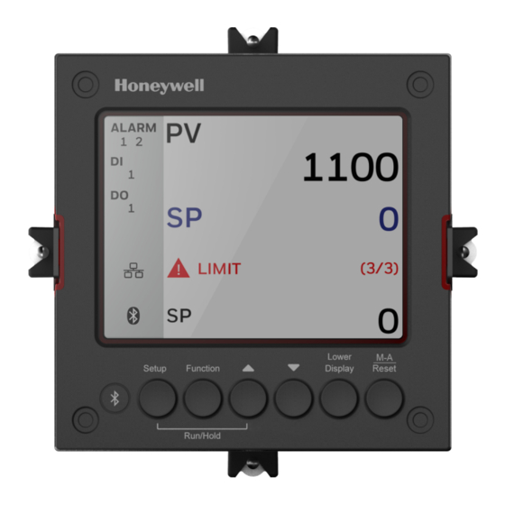
Chapter 2 - Introduction Operator Interface Function of Displays Figure 2-1: Function of Displays Table 2-1: Function of Displays Item Description Upper display shows Process Variable value (maximum 10 digits including decimal point, eg. -XXXX.X). Its unit can be F, C or none. Middle display shows working Setpoint and its value (maximum 10 digits including decimal point, eg. - Page 15 Chapter 2 - Introduction Item Description Alarm 1 and/or Alarm 2 annunciations. Digital Input 1 annunciations. Control Relay 1 annunciations. Modbus, or Ethernet communication status annunciation. Modbus: Ethernet: Grey: The function is disabled. White: The function is enabled, but the connection is not established. Blinking: The function is enabled, and the connection is established.
-
Page 16: Function Of Keys
Chapter 2 - Introduction Function of Keys Figure 2-2: Function of Keys Table 2-2: Function of Keys Item Description NEMA4X and IP66 screw attachment (each corner). Bluetooth transmitter Enables to configure and operate controllers from mobility devices (mobile phones and tablet PCs), and download/upload the complete device configuration. - Page 17 Chapter 2 - Introduction Item Description Function key Selects functions within each configuration group. When in the setup screen. The first press will set the focus to the Function Group, and the subsequent presses used to navigate between Function Group and Option Group. When in the setup screen and the focus in on the Option Group, press it to leave the focus from the Option Group, and immediately save the changes user made on the Option Group.
-
Page 18: Mobile Device App
NOTE: The default password for the UDC device is 1234. It is recommended to change the password after the first login. Mobile Device App The controller can be configured via a Honeywell EasySet. Honeywell EasySet is running on a Mobile Device, The following communication types are available on UDC2800 Limit Controller. -
Page 19: Configuration Tool Via Bluetooth
3 meters. This app can be installed on IOS 12.0 or higher operating system. See Configuration via Honeywell EasySet for more information. Figure 2-3: Screen capture of Honeywell EasySet running on a Mobile Device Features Create configurations with the application (Honeywell EasySet) running on a Mobile Device. -
Page 20: Ce Conformity (Europe)
Chapter 2 - Introduction Bluetooth communications The Bluetooth connection provides a non-intrusive wireless connection with the instrument and maintains NEMA4X and IP66 integrity. No need to get access to the back of the controller to communicate with the instrument, no need to take your screwdriver to wire the communication cable, no wiring mistake possible. -
Page 21: North America
Chapter 2 - Introduction Pollution Degree: Pollution Degree 2: Normally non-conductive pollution with occasional conductivity caused by condensation. (Ref. IEC 60664-1) EMC Classification: Group 1, Class A, ISM Equipment (EN61326-1, emissions), Industrial Equipment (EN61326-1, immunity) Method of EMC Assessment: Technical File (TF) Declaration of Conformity: 51453655 Deviation from the installation conditions specified in this manual, and the special conditions for CE conformity in Subsection... -
Page 22: Fcc
Chapter 2 - Introduction : Federal Communications Commission Radio Compliance information (FCC) contains FCC ID: 2AVFQ-MCUDISP Industry Canada (IC) contains IC: 25762-MCUDISP. This device complies with Part 15 of the FCC Rules / Innovation, Science and Economic Development Canada’s license-exempt RSS (s). - Page 23 Chapter 2 - Introduction Conformément à la réglementation d'Industrie Canada, le présent émetteur radio peut fonctionner avec une antenne d'un type et d'un gain maximal (ou inférieur) approuvé 2 pour l'émetteur par Industrie Canada. Dans le but de réduire les risques de brouillage radioélectrique à...
- Page 24 CHAPTER INSTALLATION What's in this section? The following topics are covered in this section. In this section: Overview Condensed Specifications Model Number Interpretation Limit and Alarm Relay Contact Information Mounting Wiring Wiring Diagrams Wiring the Controller Limit Control Application Diagram...
-
Page 25: Chapter 3 - Installation
Chapter 3 - Installation Overview Introduction Installation of the UDC2800 Limit Controller consists of mounting and wiring the controller according to the instructions given in this section. Read the pre-installation information, check the model number interpretation (Subsection Model Number Interpretation), and become familiar with your model selections, then proceed with installation. - Page 26 Chapter 3 - Installation Items Specifications Input Impedance: 4-20 Milliampere Input: 250 ohms 0-10 Volt Input: 200K ohms All Others: 10 megohms Maximum Lead Wire Resistance: Thermocouples: 50 ohms/leg 100 ohm, 200 ohm and 500 ohm RTD: 100 ohms/leg 100 ohm Low RTD: 10 ohms/leg Analog Input Burnout Selections: Upscale, Downscale Signal Failure...
- Page 27 Chapter 3 - Installation Items Specifications Resistive Load: 5 amps @ 120 Vac or 240 Vac or 30 Vdc Inductive Load (cosj = 0.4): 3 amps @ 130 Vac or 250 Vac Inductive Load (L/R = 7 msec): 3.5 amps @ 30 Vdc Motor: 1/6 H.P.
- Page 28 Chapter 3 - Installation Items Specifications 2000 ft (600 m) max. with Belden 9271 Twinax Cable and 120 ohm termination resistors 4000 ft. (1200 m) max. with Belden 8227 Twinax Cable and 100 ohm termination resistors Link Characteristics: Two-wire, multi-drop Modbus RTU protocol, 15 drops maximum or up to 31 drops for shorter link length.
- Page 29 Chapter 3 - Installation Items Specifications Communication Status (Bluetooth, Ethernet, and Modbus) Dimensions Overall Dimensions for more information. Wiring Screw terminals on the rear of the case. Connections See Wiring Diagrams for more information. Power 20 VA maximum (90 to 264 Vac) Consumption 15 VA maximum (24 Vac/dc) Power Inrush...
- Page 30 Chapter 3 - Installation Items Specifications Mode. All other circuits: 1.0 kV, Common Mode, and Differential Mode. The instrument can meet these test levels with no component failures, no reset, and no incorrect outputs. Radio Frequency Immunity: No effect on performance from a 5 W walkie-talkie Interference (RFI) operated at 151 or 450 MHz, one meter from the controller.
-
Page 31: Model Number Interpretation
UDC2800 Universal Digital Limit Controller Model Selection Guide The UDC2800 controller packs new powerful features while retaining all the simplicity and flexibility of the industry standard UDC2500 controller including: Enhanced Display... - Page 32 Chapter 3 - Installation Key Number _ _ _ _ _ _ _ _ _ _ _ _ _ _ _ Table I - Specify Control Output and/or Alarms Output #1 Electro Mechanical Relay (5 Amp Form C) • • Open Collector transistor output •...
- Page 33 Chapter 3 - Installation (Note 2) CE, UL, CSA and FM (Limit controller) 2 _ _ Tags None _ 0 _ • • Stainless Steel Customer ID Tag - 3 lines w/22 _ T _ • • characters/line Future None _ _ 0 •...
- Page 34 C _, R _ FM approved units with communication are limited to read only. UL listed for regulatory use only. CSA listed for regulatory use only. UDC2800 Universal Digital Controller Supplemental Accessories & Kits Description Part Number Front panel assembly, UDC 2800/2900...
-
Page 35: Limit And Alarm Relay Contact Information
English 51-52-25-166 Product Manual English 51-52-25-165 ATTENTION: It is recommended to use Honeywell provided accessories and kits. Otherwise, using non-Honeywell provided components would take risks. Limit and Alarm Relay Contact Information Limit Relay ATTENTION: The Limit relay is designed to operate in a Failsafe mode. - Page 36 Chapter 3 - Installation Table 3-2: Limit Relay Contact Information Variable NOT in Limit Variable in Limit State Limit Control State Unit Relay Power Relay Relay Wiring Indicators Indicators Contact Contact N.O. Open Open N.C. Closed Closed N.O. Closed Open N.C.
-
Page 37: Mounting
Chapter 3 - Installation Mounting Physical Considerations The controller can be mounted on either a vertical or tilted panel using the mounting kit supplied. Adequate access space must be available at the back of the panel for installation and servicing activities. -
Page 38: Overall Dimensions
Chapter 3 - Installation Overall Dimensions Dimensions and Mounting Figure 3-1: Mounting Dimensions (not to scale) -
Page 39: Mounting Method
Chapter 3 - Installation Mounting Method Before mounting the controller, refer to the nameplate on the outside of the case and make a note of the model number. It will help later when selecting the proper wiring configuration. Figure 3-2: Mounting Methods Item Description Attach screws and washers here for water protection... -
Page 40: Mounting Procedure
Chapter 3 - Installation Mounting Procedure Table 3-4: Mounting Procedure Step Action Mark and cut out the controller hole in the panel according to the dimension information. See Overall Dimensions for more information. Orient the case properly and slide it through the panel hole from the front. Remove the mounting kit from the shipping container and install the kit as follows: For normal (NEMA3/IP55) installation two mounting clips are required. ... -
Page 41: Wiring
Chapter 3 - Installation Wiring Electrical Considerations Line voltage wiring This controller is considered “rack and panel mounted equipment” per EN61010-1, Safety Requirements for Electrical Equipment for Measurement, Control, and Laboratory Use, Part 1: General Requirements. Conformity with 72/23/EEC, the Low Voltage Directive requires the user to provide adequate protection against a shock hazard. - Page 42 Chapter 3 - Installation (4 mm ) copper conductor, is recommended. Control/Alarm Circuit Wiring The insulation of wires connected to the Control/Alarm terminals shall be rated for the highest voltage involved. Extra Low Voltage (ELV) wiring (input, current output, and low voltage Control/Alarm circuits) shall be separated from HAZARDOUS LIVE (>30 Vac, 42.4 Vpeak, or 60 Vdc) wiring per Permissible Wiring Bundling, Electrical Considerations-.
-
Page 43: Wiring Diagrams
Chapter 3 - Installation Bundle No. Wire Functions Analog signal wire, such as: Input signal wire (thermocouple, 4 to 20 mA, etc.) 4-20 mA output signal wiring Digital input signals Low voltage alarm relay output wiring Low voltage wiring to solid state type control circuits Low voltage wiring to open collector type control circuits Wiring Diagrams... - Page 44 Item Description AC/DC Line Voltage Terminals. Output 3 Terminals ( Alarm #2 in the Table I of UDC2800 Universal Digital Limit Controller Model Selection Guide). ATTENTION: If they are used as Relay Outputs, the wire gauge should be AWG 14~22.
- Page 45 Chapter 3 - Installation Item Description Not used. Input #1 Terminals. Aux. Output and Digital Inputs Terminals. Communications Terminals. Figure 3-4: Mains Power Supply Item Description PROTECTIVE BONDING (grounding) of this controller and the enclosure in which it is installed, shall be in accordance with National and local electrical codes.
- Page 46 Chapter 3 - Installation Item Description CAUTION: Applying 90-264 Vac to an instrument rated for 24 Vac/dc will severely damage the instrument and is a fire and smoke hazard.
- Page 47 Chapter 3 - Installation Figure 3-5: Input 1 Connections Item Description The 250 ohm resistor for milliamp inputs is supplied with the controller when those inputs are specified. These items must be installed prior to start up when the controller is wired. For 0-20 mA applications, the resistor should be located at the transmitter terminals if Burnout detection is desired.
- Page 48 Chapter 3 - Installation Figure 3-6: Electromechanical Relay Output Item Description Electromechanical relays are rated at 5 Amps @ 125 Vac or 250 Vac or 30 Vdc. Users should size fuses accordingly. Use Fast Blow fuses only. See the table Wiring Diagrams for relay terminal connections for other Output Algorithm Types.
- Page 49 Chapter 3 - Installation Figure 3-7: Open Collector Output Item Description CAUTION: Open collector outputs are internally powered at 28 Vdc (0 mA) ~ 24 Vdc (20 mA). Connecting and external power supply will damage the controller. Electromechanical relays are rated at 5 Amps @ 125 Vac or 250 Vac or 30 Vdc. Users should size fuses accordingly.
- Page 50 Chapter 3 - Installation Figure 3-8: RS485 Communications Option Connections Item Description Do not run the communications lines in the same conduit as AC power. Use shielded twisted pair cables (Belden 9271 Twinax or equivalent). Figure 3-9: Ethernet Communications Option Connections...
- Page 51 Chapter 3 - Installation Item Description Do not run the communications lines in the same conduit as AC power. Correct connections may require the use of an Ethernet cross-over cable. Use shielded twisted pair, Category 5e (STP CAT5e) Ethernet cable. For Ethernet cable with RJ45 connector, an Ethernet Adapter Kit is required to install on the terminals.
- Page 52 Chapter 3 - Installation Figure 3-11: Transmitter Power for 4-20 mA — 2 wire Transmitter Using Open Collector Alarm 2 A2S1TY Deviation Output Figure 3-12: Transmitter Power for 4-20 mA — 2 Wire Transmitter Using Auxiliary Output...
-
Page 53: Limit Control Application Diagram
Chapter 3 - Installation Limit Control Application Diagram Limit Controller Wiring The following Limit Controller Application Diagram shows the RIGHT and WRONG way to wire the Limit Controller. Figure 3-13: Limit Controller Application Diagram... -
Page 54: Chapter 4 - Configuration
CHAPTER CONFIGURATION What's in this section? The following topics are covered in this section. In this section: Overview Configuration Prompt Hierarchy Configuration Procedure Security Set Up Group Limit Set Up Group Input 1 Set Up Group Options Set Up Group Communications Group Alarms Set Up Group Display Set Up Group... -
Page 55: Overview
Chapter 4 - Configuration Overview Introduction Configuration is a dedicated operation where you use straightforward keystroke sequences to select and establish (configure) pertinent control data best suited for your application. To assist you in the configuration process, there are prompts that appear in the upper and lower displays. - Page 56 Chapter 4 - Configuration Setup Group Function Prompts Communication Alarms Display Input1 Calib (Calibration) Auxiliary Calib (Calibration) Status...
-
Page 57: Configuration Procedure
Chapter 4 - Configuration Configuration Procedure Introduction Each of the Set-Up groups and their functions are pre-configured at the factory. The factory settings are shown in Section Configuration Record Sheet. If you want to change any of these selections or values, follow the procedure in Configuration Procedure-. -
Page 58: Security Set Up Group
Chapter 4 - Configuration Step Operation Press Result that you want to change. Change the Value Function key Enter in the value or selection of the or Selection selected function prompt. Increment key or Increment or decrement the value or Decrement key selection that appears for the selected function prompt. - Page 59 Lockout applies to one of the functional groups: Configuration, Calibration and SP. ATTENTION: Do not configure it until all configuration is complete. NOTE: In the Honeywell EasySet app, lockout options appears under the security group only after entering the password.
- Page 60 Chapter 4 - Configuration Selections or Function Range of Parameter Definition Prompt Setting None No lockout; all groups are read/write. Calibration All groups are available for read/write except for the Calibration and Keyboard Lockout groups. + Configuration All groups are read only. Calibration and Keyboard Lockout groups are not available.
-
Page 61: Limit Set Up Group
Chapter 4 - Configuration Limit Set Up Group Introduction This data deals with the type of Limit Control you want, power up Logic, setpoint high and low limits, and the default display function Prompts Table 4-4: LIMIT Group Function Prompts Function Selection or Prompt... -
Page 62: Input 1 Set Up Group
Chapter 4 - Configuration Input 1 Set Up Group Introduction This data deals with various parameters required to configure Input Function Prompts Table 4-5: INPUT 1 Group Function Prompts Selections or Function Range of Parameter Definition Prompt Setting Input 1 Type –... - Page 63 Chapter 4 - Configuration Selections or Function Range of Parameter Definition Prompt Setting TC M Low M Thermocouple Low (Ni-Ni-Moly) TC N High N Thermocouple High (Nicrosil-Nisil) TC N Low N Thermocouple Low (Nicrosil-Nisil) TC R R Thermocouple TC S S Thermocouple TC T High T Thermocouple High...
- Page 64 Chapter 4 - Configuration Selections or Function Range of Parameter Definition Prompt Setting Transmitter TC E High instruct the controller to characterize a linear input to represent a non-linear one. If characterization is TC E Low performed by the transmitter itself, then select Linear.
- Page 65 Chapter 4 - Configuration Selections or Function Range of Parameter Definition Prompt Setting Linear Square Root Input 1 High –999. To Input 1 High Range Value in engineering units is Value 9999. Floating displayed for all inputs but can only be configured for linear or square root transmitter engineering characterization.
- Page 66 Chapter 4 - Configuration Selections or Function Range of Parameter Definition Prompt Setting FM version Input 1 Filter 0 to 120 Filter for Input 1 —A software digital filter is seconds No provided for Input 1 to smooth the input signal. filter = 0 You can configure the first order lag time constant from 1 to 120 seconds.
-
Page 67: Options Set Up Group
Chapter 4 - Configuration Options Set Up Group Introduction The Options group lets you configure the remote mode switch (Digital Inputs) to a specific contact closure response or configure the Auxiliary Output to be a specific selection with desired scaling. Function Prompts Table 4-6: OPTION Group Function Prompts Selection or... - Page 68 Chapter 4 - Configuration Selection or Function Range of Parameter Prompt Setting Definition Lower Display Upper Display NOTE: If PV or deviation value goes below Auxiliary output low scaling factor, display percentage is set to 0 % and the output current driven is limited to 4 mA.
-
Page 69: Communications Group
Chapter 4 - Configuration Communications Group Introduction The Communications group lets you configure the controller with Easyset, a mobile app that communicates through Bluetooth, and lets a Modbus® client/master host communicate with the controller via Ethernet TCP/IP protocol. A controller with the Ethernet option looks for messages from the host computer. - Page 70 Chapter 4 - Configuration Selections or Function Range of Parameter Definition Prompt Setting Ethernet Ethernet —Enables Ethernet communication port. Modbus 1 to 99 Communications station address —This is a number Address that is assigned to a controller that is to be used with the communications option.
- Page 71 Chapter 4 - Configuration Selections or Function Range of Parameter Definition Prompt Setting communication port. The default value is 10.0.0.2. Subnet Mask 0.0.0.0 to Subnet Mask address, ranging from 0.0.0.0 to Address 255.255.255.2 255.255.255.255. It only applies to Ethernet communication port. The default value is 255.255.255.255.
- Page 72 Chapter 4 - Configuration Selections or Function Range of Parameter Definition Prompt Setting Computer SP Computer Setpoint Units Unit Engineering Engineering units Unit Percent Percent of PV range Local Local Loopback tests the RS-485 communications Loopback port. It is not used for any other communications port.
-
Page 73: Alarms Set Up Group
Chapter 4 - Configuration Alarms Set Up Group Introduction An alarm is an indication that an event that you have configured (for example—Process Variable) has exceeded one or more alarm limits. There are two alarms available. Each alarm has two setpoints. You can configure each of these two setpoints to alarm on various controller parameters. - Page 74 Chapter 4 - Configuration Function Selection or Range Parameter Prompt of Setting Definition Lower Display Upper Display ATTENTION: Alarm set-point range is configurable from 0 to 9999. SHED Shed from Communications Failsafe Failsafe PV Rate of Change PV Rate of Change ATTENTION: Alarm set-point range is configurable from 0 to 9999.
- Page 75 Chapter 4 - Configuration Function Selection or Range Parameter Prompt of Setting Definition Lower Display Upper Display This prompt does not appear for Alarm Types that do not use values. For example: A1S1 Type = DI 1 Actuated. A1S1 State ALARM 1 SETPOINT 1 STATE—Select whether you want the alarm type chosen in prompt HIGH Alarm...
- Page 76 Chapter 4 - Configuration Function Selection or Range Parameter Prompt of Setting Definition Lower Display Upper Display 100 % away from the alarm setpoint. Configure the hysteresis of the alarms based on INPUT signals as a % of input range span. Configure the hysteresis of the alarm based on OUTPUT signals as a % of the full scale output range.
- Page 77 Chapter 4 - Configuration Function Selection or Range Parameter Prompt of Setting Definition Lower Display Upper Display The selections are the same as A1S1 Type. ATTENTION: Not applicable with Relay Duplex unless using Dual Relay PWA. A2S2 Value ALARM 2 SETPOINT 2 VALUE—This is the value at which you want the alarm type chosen in prompt A2S2 Type to actuate.
- Page 78 Chapter 4 - Configuration Function Selection or Range Parameter Prompt of Setting Definition Lower Display Upper Display Disable alarm is suppressed until the parameter gets Alarm 1 to the non-alarm limit or band. Alarm blocking Alarm 2 affects both alarm setpoints. Alarm 1 &...
-
Page 79: Display Set Up Group
Chapter 4 - Configuration Display Set Up Group Introduction This group includes selections for Decimal place, Units of temperature, and Language. Function Prompts Table 4-9: Display Group Function Prompts Function Selections or Parameter Definition Prompt Range of Setting Decimal Decimal Point Location —This selection Digits determines where the decimal point appears in the main screen display. -
Page 80: Input1 Calib Set Up Group
Chapter 4 - Configuration Function Selections or Parameter Definition Prompt Range of Setting Disable Disable Diagnostic Messages Theme Dark This selection applies the Dark theme to the UDC device. White This selection applies the White theme to the UDC device. NOTE: After changing the theme, the UDC device must be restarted for the new theme to take effect. -
Page 81: Auxiliary Calib Set Up Group
Chapter 4 - Configuration Function Selections or Range of Parameter Definition Prompt Setting Input 1 It depends on the input Adjust your calibration device to an output Span type. signal equal to the 100 % range value for your particular input sensor. See the table Voltage, Milliamp and Resistance Equivalents for Input Range Values... -
Page 82: Configuration Record Sheet
Chapter 4 - Configuration Configuration Record Sheet Enter the value or selection for each prompt on this sheet so you will have a record of how your controller was configured. Group Function Value or Factory Setting Prompt Prompt Selection Security Password __________ Lockout... - Page 83 (Accessible via Bluetooth MAC Address Read only XX:XX:XX:XX:XX:XX Communication Communication Type __________ Disable set up group or Modbus Address __________ Honeywell Baud Rate __________ 19200 EasySet) Response Delay __________ Word Order for Float __________ FP B 0123 Shed Function __________...
- Page 84 XX:XX:XX:XX:XX:XX (Accessible via Communication Type __________ Disable Communication Modbus Address __________ set up group or Baud Rate __________ 19200 Honeywell Response Delay __________ EasySet) Word Order for Float __________ FP B 0123 Ethernet Address __________ 10.0.0.2 Subnet Mask Address __________ 255.255.255.0...
-
Page 85: Chapter 5 - Operating The Limit Controller
CHAPTER OPERATING THE LIMIT CONTROLLER What's in this section? The following topics are covered in this section. In this section: Overview Operator Interface Entering a Security Code Lockout Feature Monitoring Your Controller Start Up Procedure for Operation Setpoints Alarm Setpoints... -
Page 86: Overview
Chapter 5 - Operating the Limit Controller Overview Introduction This section gives you all the information necessary to help you monitor your controller including an Operator Interface overview, how to lockout changes to the controller, entering a security code, and monitoring the displays. -
Page 87: Entering A Security Code
Chapter 5 - Operating the Limit Controller Entering a Security Code Introduction The level of keyboard lockout may be changed in the Setup mode. However, knowledge of a security code number (0 to 9999) may be required to change from one level of lockout to another. When a controller leaves the factory, it has a security code of 1234 which should be entered and changed after the first power up or after restoring to factory default settings. -
Page 88: Lockout Feature
Chapter 5 - Operating the Limit Controller Lockout Feature Introduction The lockout feature is used to inhibit changes (via keyboard) of certain functions or parameters by unauthorized personnel. See Security Set Up Group for more information. Lockout levels NOTE: In the EasySet app, lockout options appears under the security group only after entering the password. -
Page 89: Viewing The Operating Parameters
Chapter 5 - Operating the Limit Controller Viewing the operating parameters Under the main screen, press the Lower Display key to scroll through the operating parameters listed in table below. The lower display will show only those parameters and their values that apply to your specific model. -
Page 90: Diagnostic Messages
Chapter 5 - Operating the Limit Controller Diagnostic Messages The UDC2800 limit controller performs background tests to verify data and memory integrity. If there is a malfunction, an error message is displays. In the case of more than one simultaneous malfunction, the messages are displayed sequentially on the lower display. -
Page 91: Start Up Procedure For Operation
Decrement key at which you want the process variable maintained. Setpoints Introduction You can configure the following setpoints for the UDC2800 Limit Controller controller. A Single Local Setpoint Change the Setpoint value Table 5-3: Procedure for Changing the Local Setpoints... - Page 92 Chapter 5 - Operating the Limit Controller...
-
Page 93: Alarm Setpoints
Chapter 5 - Operating the Limit Controller Alarm Setpoints Introduction An alarm consists of a relay contact and an operator interface indication. The alarm relay is de-energized if setpoint 1 is exceeded. The alarm relay is energized when the monitored value goes into the allowed region by more than the hysteresis. - Page 94 Chapter 5 - Operating the Limit Controller Step Operation Press Result Select the Function key Enter in the first function prompt A1S1 Type. Alarm Increment key or Until you see the required Alarm setpoint. Setpoint Decrement key Values A1S1 Value = Alarm 1, Setpoint 1 Value A1S2 Value = Alarm 1, Setpoint 2 Value A2S1 Value = Alarm 2, Setpoint 1 Value A2S2 Value = Alarm 2, Setpoint 2 Value...
-
Page 95: Chapter 6 - Input Calibration
CHAPTER INPUT CALIBRATION What's in this section? The following topics are covered in this section. In this section: Overview Minimum and Maximum Range Values Preliminary Information Input 1 Set up Wiring Input 1 Calibration Procedure Restore Input Factory Calibration... -
Page 96: Overview
Introduction This section describes the field calibration procedures for Input 1. All input actuations in every UDC2800 limit controller are fully factory-calibrated and are ready for configuration by the user. Field Calibration can improve the accuracy of the Controller if necessary for a particular application. -
Page 97: Minimum And Maximum Range Values
Chapter 6 - Input Calibration Minimum and Maximum Range Values Select the Range Values Calibrate the controller for the minimum (0 %) and maximum (100 %) range values of your particular input type. Select the Voltage, Current or Resistance equivalents for 0 % and 100 % range values from Table 5-1 ... - Page 98 Chapter 6 - Input Calibration PV Input Range Values Range Sensor Type °F °C 100% TC M High (Ni-Ni-Moly) 32 to 0 to 0.000 mV 71.773 mV 2500 1371 TC M Low (Ni-Ni-Moly) 32 to 0 to 0.000 mV 31.825 mV 1260 TC N High (Nicrosil-Nisil) 0 to...
- Page 99 Chapter 6 - Input Calibration PV Input Range Values Range Sensor Type °F °C 100% to 649 ohms ohms 1200 RTD Pt500 –300 –184 126.012 1646.445 to 649 ohms ohms 1200 TC PR40-PR20 32 to 0 to 0.000 mV 4.933 mV 3416 1880 Linear...
-
Page 100: Preliminary Information
Chapter 6 - Input Calibration Preliminary Information Disconnect the Field Wiring Tag and disconnect any field wiring connected to the input terminals on the rear of the controller. Figure 6-1: Input 1 Wiring Terminals Equipment Needed Table below lists the equipment you will need to calibrate the specific types of inputs that are listed in the table. -
Page 101: Input 1 Set Up Wiring
Place current source at zero before switching ON. Do not switch current sources OFF/ON while connected to the UDC2800 input. Input 1 Set up Wiring Thermocouple Input using a Millivolt Source See Figure Wiring Connections for Thermocouple Inputs using a Millivolt Source"... - Page 102 Chapter 6 - Input Calibration RTD Inputs Refer to Input 1 Set up Wiring - and wire the controller according to the procedure given in Set Up Wiring Procedure for RTD Inputs. Table 6-4: Set Up Wiring Procedure for RTD Inputs Step Action Connect the copper leads from the calibrator to the Input #1...
- Page 103 Chapter 6 - Input Calibration Figure 6-4: Wiring Connections for, Millivolts, Volts or Thermocouple Differential (Except 0 to 10 Volts) Table 6-5: Wiring Connections for Thermocouple Differential, Millivolts or Volts (Except 0 to 10 Volts) Step Action Connect the copper leads from the calibrator to the Input #1 terminals as shown in figure Wiring Connections for Thermocouple Inputs using a Millivolt Source.
-
Page 104: Input 1 Calibration Procedure
Chapter 6 - Input Calibration Figure 6-5: Wiring Connections for 0 to 20 mA or 4 to 20 mA Inputs Input 1 Calibration Procedure Preliminary Steps Apply power and allow the controller to warm up for 30 minutes before you calibrate. Before beginning the procedure, see Input 1 Set up Wiring more information. - Page 105 Chapter 6 - Input Calibration Procedure The calibration procedure for Input #1 is listed in table below. Table 6-7: Input 1 or 2 Calibration Procedure Step Operation Press Result Enter Setup key Enter into the setup mode. Calibration Increment Until you see "Input 1 Calib". Mode key or Decrement...
- Page 106 Chapter 6 - Input Calibration Step Operation Press Result Calibrate 100 Increment You will see Input 1 Span. key or Adjust your calibration device to an output Decrement signal equal to the 100 % range value for your particular input sensor. See the table Voltage, Milliamp and Resistance Equivalents for Input ...
-
Page 107: Restore Input Factory Calibration
Chapter 6 - Input Calibration Step Operation Press Result Mode Exit the calibration mode. Lower Display key Restore Input Factory Calibration Introduction The factory calibration constants for all the input actuation types that can be used with the controller are stored in its non-volatile memory. Thus, you can quickly restore the “Factory Calibration”... - Page 108 Chapter 6 - Input Calibration Table 6-8: Restore Factory Calibration Step Operation Press Result Setup key Until you see Security. Lockout to Function Enter into the first function prompt Password of the None Security set up group. Press the Function key again to enter the correct password.
- Page 109 Chapter 6 - Input Calibration Step Operation Press Result Operation The factory calibration will be restored. If the problem is not corrected, contact your Honeywell representative.
-
Page 110: Chapter 7 - Output Calibration
CHAPTER OUTPUT CALIBRATION What's in this section? The following topics are covered in this section. In this section: Overview Auxiliary Output Calibration Restore Output Factory Calibration... -
Page 111: Overview
Chapter 7 - Output Calibration Overview Introduction This section describes the field calibration procedures for the Auxiliary Output. WARNING: OUTPUT CALIBRATION MAY REQUIRE ACCESS TO HAZARDOUS LIVE CIRCUITS, AND SHOULD ONLY BE PERFORMED BY QUALIFIED SERVICE PERSONNEL. MORE THAN ONE SWITCH MAY BE REQUIRED TO DE-ENERGIZE UNIT BEFORE CALIBRATION. - Page 112 Chapter 7 - Output Calibration Step Action Set LOCK in the Tuning Set Up group to NONE. Tag and disconnect the field wiring, at the rear of the controller, from terminals 12 (+) and 13 (–). See Wiring Connections for Calibrating Auxiliary Output.
- Page 113 Chapter 7 - Output Calibration Table 7-2: Auxiliary Output Calibration Procedure Step Operation Press Result Enter Setup key Enter into the Setup mode. Calibration Setup key or Until you see Auxiliary Calib. Mode Increment key or Decrement Calibrate 0 % Function Enter into the first function prompt Zero Value of the Auxiliary Calib set up group.
-
Page 114: Restore Output Factory Calibration
Chapter 7 - Output Calibration Step Operation Press Result Display key Restore Output Factory Calibration Introduction The factory calibration constants for the Current and Auxiliary Outputs are stored in its non-volatile memory. Thus, you can quickly restore the “Factory Calibration” for those outputs by simply changing the CO Range setting for that output to the other setting and then changing it back to the original type. - Page 115 Chapter 7 - Output Calibration Table 7-3: Restore Factory Calibration Step Operation Press Result Select Setup key Until you see Security. Lockout to Function key Enter into the first function prompt None Password of the Security set up group. Press the Function key again to enter the correct password.
- Page 116 Chapter 7 - Output Calibration Step Operation Press Result Honeywell representative.
- Page 117 CHAPTER TROUBLESHOOTING/SERVICE What's in this section? The following topics are covered in this section. In this section: Overview Troubleshooting Aids Power-up Tests Status Tests Background Tests and Diagnostic Controller Failure Symptoms Troubleshooting Procedures Restoring Factory Configuration...
-
Page 118: Chapter 8 - Troubleshooting/Service
Installation related problems Read the Installation section in this manual to make sure the UDC2800 has been properly installed. The installation section provides information on protection against electrical noise, connecting external equipment to the controller, and shielding and routing external wiring. -
Page 119: Troubleshooting Aids
Chapter 8 - Troubleshooting/Service Troubleshooting Aids Overall error messages An error message can occur: At power-up. See Power-up Tests for more information. When the Status Tests are requested. See Status Tests for more information. During continuous background tests while in normal operation. See Background Tests and Diagnostic for more information. -
Page 120: Power-Up Tests
Status set up group. You can see the software version version then. Please give this number to the Customer Support person. It will indicate which version of UDC2800 you have and help them determine a solution to your problem. Power-up Tests... -
Page 121: Status Tests
Chapter 8 - Troubleshooting/Service Status Tests Introduction When required, the results of these tests can be checked to determine the reason the controller has gone to Failsafe. How to check the status tests The procedure in table below tells you how to display the results of the status tests. -
Page 122: Background Tests And Diagnostic
Chapter 8 - Troubleshooting/Service Background Tests and Diagnostic Introduction This instrument performs ongoing background tests to verify data and memory integrity. If there is a malfunction, a diagnostic message will be displayed (blinking) in the diagnostics display. In the case of simultaneous malfunctions, the messages will appear in sequence in the diagnostics display. Table below lists these background tests, the reason for their failure, and how to correct the problem. - Page 123 Chapter 8 - Troubleshooting/Service Lower Display Reason for Failure How to Correct the Problem Calibration Test Calibration test failed at start Run through STATUS check to Error determine the reason for the failure. Restore factory settings. See Restoring Factory Configuration for more information.
- Page 124 Chapter 8 - Troubleshooting/Service Lower Display Reason for Failure How to Correct the Problem process input is outside the actuation are configured range limits. properly. Check the input source. Restore the factory calibration. (See Restore Input Factory Calibration for more information.) Field calibrate.
- Page 125 Chapter 8 - Troubleshooting/Service Lower Display Reason for Failure How to Correct the Problem Position Step Output Calibration Slidewire. for more information. Slidewire calibration never performed. Slidewire Fail See Troubleshooting Procedures Input 2 Type is configured as for more information. Slidewire.
-
Page 126: Controller Failure Symptoms
Chapter 8 - Troubleshooting/Service Controller Failure Symptoms Introduction In addition to the error message prompts, there are failure symptoms that can be identified by noting how the controller displays and indicators are reacting. Symptoms Compare your symptoms with those shown in table below. Table 8-4: Controller Failure Symptoms Upper Lower... -
Page 127: Troubleshooting Procedures
Chapter 8 - Troubleshooting/Service Upper Lower Controller Troubleshooting Indicators Probable Cause Display Display Output Procedure Output Other symptoms If a set of symptoms or prompts other than the one you started with appears while troubleshooting, re-evaluate the symptoms. This may lead to a different troubleshooting procedure. -
Page 128: Procedure #2
Chapter 8 - Troubleshooting/Service Table 8-5: Troubleshooting Power Failure Symptoms Step What to do How to do it Check the AC line voltage. Use a voltmeter to measure the AC voltage across terminals L1 and L2 on the rear terminal panel of the controller. Check the earth ground connection. - Page 129 Chapter 8 - Troubleshooting/Service Step What to do How to do it See Installation for more information. Change the relay and/or Installation instructions supplied with the new the current output board. relay or board. Change MCU board. Installation instructions supplied with the new board.
-
Page 130: Procedure #3
Chapter 8 - Troubleshooting/Service Procedure #3 This table explains how to troubleshoot a Keyboard failure. Table 8-7: Troubleshooting a Keyboard Failure Step What to do How to do it Make sure the keyboard is Withdraw the chassis from the case and visually connected properly to the inspect the connection. -
Page 131: Procedure #5
This table explains how to troubleshoot an Ethernet Communications failure. Table 8-9: Troubleshooting an Ethernet Communications Failure Step What to do How to do it Check the IP See Communication set up group and Honeywell address, Subnet EasySet. Mask address and Gateway address settings. Check if the... -
Page 132: Procedure #6
Chapter 8 - Troubleshooting/Service Step What to do How to do it Ethernet when there is no Ethernet connection. Connection is active. when there is an Ethernet connection, solid White but no data exchange. when there is an white and blinks once per second Ethernet connection and data exchange. -
Page 133: Restoring Factory Configuration
Chapter 8 - Troubleshooting/Service Step What to do How to do it Change Controller Restoring Factory Configuration Introduction This procedure restores the configuration of the instrument back to the Factory Settings. See Configuration Record Sheet for more information. ATTENTION: Restoring the factory configuration overwrites all user-entered configuration changes. - Page 134 Chapter 8 - Troubleshooting/Service Step Operation Press Result Enter Function key The Lockout function prompt appears. Restoring Increment key or Until you see Restoring Settings. Settings Decrement key Function key Enter into the configuration prompt of Restoring Settings. Increment key or Until you see Enable.
-
Page 135: Chapter 9 - Parts List
CHAPTER PARTS LIST What's in this section? The following topics are covered in this section. In this section: Exploded View Removing the chassis... -
Page 136: Exploded View
Chapter 9 - Parts List Exploded View Introduction This figure shows an exploded view of the UDC2800 Controller. Each part is labeled with a key number. The part numbers are listed by key number in table Parts Identification. NOTE: Not all parts are standard. - Page 137 Chapter 9 - Parts List...
- Page 138 Chapter 9 - Parts List Table 9-1: Parts Identification Part Number Description Number 50159507-501 Front panel assembly, UDC 2800/2900 51308438-528 Power/Output PWA without E-M Relays (90-264 Vac Operation) 51308438-529 Power/Output PWA with E-M Relays (90-264 Vac Operation) 51308440-526 Power/Output PWA with E-M Relays (24 Vac/dc Operation) 51308448-526 Auxiliary Output/Digital Input PWA...
- Page 139 Chapter 9 - Parts List Part Number Description Number 30731996-506 4-20 mA Input Resistor Assembly (250 ohm) 50006787-001 CR2032 Battery. Battery is installed in MCU display. For more information, see the following figures. NOTE: Battery is not used for the current release.
- Page 140 Chapter 9 - Parts List Figure 9-2: 50159507 Exploded View Key Number Part Number Description 50150597-501 CHASSIS ASSEMBLY, UDC 50152823-501 TFT-LCD module for UDC2800, CTM320240N01 51308456-526 MCU/Display PWA...
-
Page 141: Removing The Chassis
Chapter 9 - Parts List Removing the chassis Using a thin screwdriver, gently twist the screwdriver to pry the side tabs from the front face. Pry just enough to release it, otherwise you’ll bend or break the tab. If you break or bend the tab and can’t reattach the front snugly, you’ll need to reattach the front using the 4 NEMA4 screws provided. -
Page 142: Chapter 10 - Configuration Via Honeywell Easyset
What's in this section? The following topics are covered in this section. In this section: Overview Communications Setup Upload Configuration Offline Configuration Download Online Configuration Maintenance Data About EasySet Firmware update through Easyset app Transfer configuration from the legacy device to the UDC2800... -
Page 143: Overview
NOTE: It is recommended to use the default keyboard when using the EasySet app on an Android device. NOTE: It is recommended to use the Honeywell EasySet app on 5 inch and above screen size iOS mobiles for a better experience. -
Page 144: Communications Setup
Chapter 10 - Configuration via Honeywell EasySet Table 10-1: Description of icons Item Description The Select Device Tab shows list of available UDC devices. It is used to set up communications before uploading or downloading instrument configurations. See Communications Setup for more information. - Page 145 Chapter 10 - Configuration via Honeywell EasySet Open the EasySet app. The Bluetooth permission pop-up appears. IOS app Android app NOTE: In Android device, if the Easyset app opened for the first time, users need to allow access permission. Location It is recommenced to choose Precise location for better results.
- Page 146 Chapter 10 - Configuration via Honeywell EasySet Click , all available controllers are detected and Select Device displayed with Bluetooth IDs. IOS app Android app NOTE: The UDC device's Bluetooth ID appears in the communications group on the controller screen.
- Page 147 Chapter 10 - Configuration via Honeywell EasySet Click , Bluetooth pairing request dialog appears. CONNECT NOTE: The UDC device displays a pairing code. Record the code. Enter the UDC device pairing code, and then click Pair IOS app Android app Once Bluetooth pair is success, enter a PIN dialog appears.
- Page 148 Chapter 10 - Configuration via Honeywell EasySet IOS app Android app Click IOS app Android app ATTENTION: Once the UDC device is connected to the EasySet app through Bluetooth, do not disable or turn off the Bluetooth function in the UDC device.
-
Page 149: Upload Configuration
Chapter 10 - Configuration via Honeywell EasySet NOTE: The user must disconnect the current device from the EasySet app before connecting to the new device. ATTENTION: The EasySet app does not allow the user to connect to new devices if a UDC device is paired with the app but the PIN is not entered. - Page 150 Chapter 10 - Configuration via Honeywell EasySet IOS app Android app NOTE: To terminate upload, click Stop If upload is successful, Users can save the configuration. Click , and enter the Save File Name Description IOS app Android app Click .
-
Page 151: Offline Configuration
Chapter 10 - Configuration via Honeywell EasySet Offline Configuration Offline Configuration lets users to edit an instrument’s configuration file for later downloading to the instrument. This operation is mostly used for initial configuration, where the configuration from one instrument is copied, duplicated, or modified and then downloaded to other instruments. - Page 152 Chapter 10 - Configuration via Honeywell EasySet IOS app Android app Select a group and edit configurations. NOTE: The groups are organized exactly as on the instrument itself. IOS app Android app...
- Page 153 Chapter 10 - Configuration via Honeywell EasySet If an analog configuration is highlighted with red text or a digital configuration is shown blank, it means that the stored value is now out of range, either because of previous changes to the instrument’s configuration or because of incompatibilities with...
-
Page 154: Export Configuration
Download reflect the changes in the UDC device. See Download. Export configuration Users can Export the UDC2800 offline configuration files to .cvt format using the Export option. The exported .cvt files can import to other UDC2800 devices. Open the app. - Page 155 Chapter 10 - Configuration via Honeywell EasySet IOS app Android app Configure the all parameters and Save the file. Click . Export options appears. Export Click and select the location, and click Save to Files Save Exported pop-up appears, click...
-
Page 156: Import Configuration
Chapter 10 - Configuration via Honeywell EasySet Import configuration Using the Import option, users can import the UDC2800 configuration files (.cvt) to the UDC device through the app. Open the mail that contains configuration (.cvt) file. Download the file and save to the IOS mobile. -
Page 157: Download
Chapter 10 - Configuration via Honeywell EasySet Click the arrow at the top left corner to return to the Dashboard page. Click .See Download. Download Download Using the Download option, users can download saved and offline configurations from the EasySet app to the instrument. -
Page 158: Online Configuration
Chapter 10 - Configuration via Honeywell EasySet IOS app Android app Select Device Type File List Item Description Device Select the device type whose configuration you want to Type download, e.g. UDC2800. File List Previously saved configuration files are shown. - Page 159 Chapter 10 - Configuration via Honeywell EasySet IOS app Android app Click to begin upload. Status of upload (% complete) is Start shown. IOS app Android app NOTE: To terminate upload, click Stop If upload is successful, configurable groups appear.
- Page 160 Chapter 10 - Configuration via Honeywell EasySet IOS app Android app Select a group and edit configurations. NOTE: The groups are organized exactly as on the instrument itself. IOS app Android app...
- Page 161 Chapter 10 - Configuration via Honeywell EasySet If an analog configuration is highlighted with red text or a digital configuration is shown blank, it means that the value read up from the instrument is now out of range, either because of previous changes to the instrument’s configuration or because of...
-
Page 162: Maintenance Data
Chapter 10 - Configuration via Honeywell EasySet IOS app Android app NOTE: If user do not want to save the configuration, click Cancel NOTE: Click the icon to reflect the UDC device's Refresh configured settings in the Honeywell EasySet app. - Page 163 Chapter 10 - Configuration via Honeywell EasySet IOS app Android app Click . Loop data page appears. Loop Data Select the loop from the drop-down list, the loop data appears. IOS app Android app NOTE: To refresh the loop data, click the icon.
- Page 164 Chapter 10 - Configuration via Honeywell EasySet Click . The Digital Inputs Details page appears. Digital Inputs IOS app Android app NOTE: To refresh Digital Input Details, click the Refresh icon. Click the arrow icon at the top left corner to return to the loop data page.
- Page 165 Chapter 10 - Configuration via Honeywell EasySet IOS app Android app NOTE: To refresh Alarms Details, click the icon. Refresh Click the arrow icon at the top left corner to return to the loop data page. Click the arrow icon at the top left corner to return to the maintenance page.
- Page 166 Chapter 10 - Configuration via Honeywell EasySet IOS app Android app NOTE: The latest EasySet App supports only bluetooth communication. Click the arrow icon at the top left corner to return to the maintenance page and click . Status data page appears.
-
Page 167: About Easyset
IOS app Android app Firmware update through Easyset app Users can update the UDC2800 Limit Controller device firmware using Honeywell EasySet IOS or Android app. NOTE: This Easyset IOS app can be installed on IOS 12.0 or higher operating system. - Page 168 Chapter 10 - Configuration via Honeywell EasySet Prerequisites Connect to the UDC2800 limit controller device. See Communications Setup for more information. Download the firmware package Go to Honeywell Process Solutions website (https://process.honeywell.com). Click at the top-right corner of the page.
- Page 169 Chapter 10 - Configuration via Honeywell EasySet On EasySet IOS app On EasySet Android app Click the share icon. Share options appear. Click and select app. More EasySet Firmware file is imported to the app. EasySet Firmware file is imported to the app.
- Page 170 Chapter 10 - Configuration via Honeywell EasySet IOS app Android app Click and then click Firmware Update START IOS app Android app Firmware update process is started.
- Page 171 Chapter 10 - Configuration via Honeywell EasySet IOS app Android app ATTENTION: Do not close the EasySet app during firmware update. ATTENTION: Do not turn off the UDC device during firmware update. ATTENTION: Keep the mobile and the UDC device in the Bluetooth range while updating the firmware.
-
Page 172: Transfer Configuration From The Legacy Device To The Udc2800
Chapter 10 - Configuration via Honeywell EasySet IOS app Android app ATTENTION: The device takes some time to reboot. Do not turn off or stop the device. Once the device restarts, the new firmware is installed in the device. NOTE: The default password for the UDC device is 1234. It is recommended to change the password after the first login. - Page 173 Chapter 10 - Configuration via Honeywell EasySet Select configuration file and click . A Dialog appears with the Next selected file for export. Click and select the export file destination path. Click Browse...
- Page 174 Chapter 10 - Configuration via Honeywell EasySet Click Export. A confirmation dialog box appears. The configuration file is exported in .csv format. Send .csv file through mail to import configuration in UDC 2800 limit controller device. Import configuration to the UDC 2800 using Easy Set Set up communications before uploading or downloading instrument configurations.
- Page 175 Chapter 10 - Configuration via Honeywell EasySet Click and select app. More EasySet Configuration file is uploaded to the app.
- Page 176 Chapter 10 - Configuration via Honeywell EasySet Open the app. EasySet Click > . The Download Files page appears Menu Downloads NOTE: The pop-up appears on the Template file NOT FOUND download page if the configuration file is not uploaded to...
- Page 177 Chapter 10 - Configuration via Honeywell EasySet ATTENTION: The UDC device must Factory reset from the controller side before downloading any configuration (.csv) file. Click the icon to download configuration. Download The Success dialog appears. Click...
- Page 178 Chapter 10 - Configuration via Honeywell EasySet ATTENTION: As the menu layout for the UDC 2800 changes, the old device SPP and Security settings do not migrate. The user must configure the settings manually for the first time. Legacy UDC device configuration is successfully imported to the...
-
Page 179: Chapter 11 - Modbus Rtu Function Codes
CHAPTER MODBUS RTU FUNCTION CODES What's in this section? The following topics are covered in this section. In this section: Overview General Information Function Code 20 (14h) - Read Configuration Reference Data Function Code 21 (15h) - Write Configuration Reference Data Modbus Read, Write and Override Parameters plus Exception Codes... -
Page 180: Overview
Chapter 11 - Modbus RTU Function Codes Overview This section describes the function codes needed to upload and download the configuration from a host computer into this instrument. NOTE: The UDC 2800 Limit Controller Modbus address are different with legacy UDC limit controller modules. Table 11-1: Modbus Function Codes 20&21 Definitions Function Name... - Page 181 Chapter 11 - Modbus RTU Function Codes Other Modbus Codes For Modbus codes other than for accessing configuration and process-related data for this controller, see the Modbus RTU Serial Communications User Manual # 51-55-25-66. Table 11-2: Integer Parameter Type Register Numbers Name Access Notes...
- Page 182 Chapter 11 - Modbus RTU Function Codes Register Numbers Name Access Notes (Dec) SUPPORTED 2 = Read/Write Value (float high word) Read / Write Value (float low word) SUPPORTED Low Range (float high word) SUPPORTED Low Range (float low word) SUPPORTED High Range (float high word)
-
Page 183: Function Code 20 (14H) - Read Configuration Reference Data
Chapter 11 - Modbus RTU Function Codes Function Code 20 (14h) - Read Configuration Reference Data Description Function code 20 (14 Hex) is used in this instrument to read information stored in its configuration database. EachUDC2300 configuration item is explicitly addressed by a file number and register address. - Page 184 Chapter 11 - Modbus RTU Function Codes Data byte count heading The Data Byte Count is the number of data bytes of the sub response including the Reference Type but not including itself. A floating point sub response has four bytes of data and one byte representing the reference type making the data byte count equal to five.
-
Page 185: Read Configuration Examples
Chapter 11 - Modbus RTU Function Codes Read Configuration Examples Example #1 The following is an example of a request to read the Gain 1 value using Function code 20. Request Message (Read Input 1 HIGH value = ID Tag 001) 02 14 07 06 00 03 00 CE 00 02 (CRC16) Where: 02 = Address... -
Page 186: Function Code 21 (15H) - Write Configuration Reference Data
Chapter 11 - Modbus RTU Function Codes Where: 02 = Address 14 = Function Code 20 (14 Hex) 0E = Byte Count 06 = Reference Type (IEEE Floating Point) 00,03 = File Number (Access Data Value) 00,27 = Register Address (Standard Access LSP #1 - ID Tag 39) 00,02 = Register Count to read (Floating Point Data) 06 = Reference Type (IEEE Floating Point) 00,03 = File Number (Access Data Value) 00,35 = Register Address (Standard Access LSP #2 - ID Tag 53) - Page 187 Chapter 11 - Modbus RTU Function Codes Integer format is used to write to “Digital” configuration items. Floating Point format is used to write to “Analog” configuration items as defined by the configuration ID tags. Write Restrictions Care should be taken not to exceed the 100,000 write limit of the EEROM.
- Page 188 Chapter 11 - Modbus RTU Function Codes File Number The file number word contains the register number from the register address structure shown in Integer Parameter Type and Floating Point Parameter Type. Although the register address structure tables indicate up to 13 data registers are available for access, only register address 3 is currently supported.
-
Page 189: Write Configuration Examples
Chapter 11 - Modbus RTU Function Codes Restrictions on Parameter Numbers in One Message The maximum number of writeable parameters per write request is 1. Write Configuration Examples Example #1 The following is an example of a request to write the Gain 1 value using Function code 21 (15 Hex). -
Page 190: Overview
Chapter 11 - Modbus RTU Function Codes Overview Introduction This section contains information concerning Reading, Writing, and Overriding parameters in this instrument. There are two types of parameters: Data Transfer—These parameters include reading control data, option status, and reading or changing setpoints. Configuration Data—All the configuration data is listed in the order in which it appears in the controller. - Page 191 Chapter 11 - Modbus RTU Function Codes Digital Parameters Whenever digital configuration register addresses are updated via communications, the non-volatile memory is updated as soon as the message is received. Communications Transfer Rates Reads minimum 20mS and writes minimum 200mS Supported Function Codes Bluetooth port 20 and 21 RS485 and Ethernet ports 1,2,3,4,6,16,17,20,21...
-
Page 192: Reading Control Data
Chapter 11 - Modbus RTU Function Codes Reading Control Data Overview The following control data can be read from this instrument: Input 1 Register Addresses Use the identifying codes listed in Control Data Parameters to read the specific items. A Write request for these codes will result in an Error message. Table 11-6: Control Data Parameters Parameter Register... -
Page 193: Miscellaneous Read Only
Chapter 11 - Modbus RTU Function Codes The data field in the response message will be a decimal number from 0 to 255. Convert the decimal number to binary as shown in the figure below to determine which options are or are not active. Figure 11-1: Software Option Status Information Miscellaneous Read Only Register Addresses for Read Only... -
Page 194: Setpoints
Chapter 11 - Modbus RTU Function Codes Setpoints You can use two separate local setpoints in the controller. The identifying register addresses listed in the following table allow you to select which setpoint you want to use and to enter a value in Engineering Units (whichever is selected at register address 8D7 (Hex)) for that setpoint via communications. - Page 195 Chapter 11 - Modbus RTU Function Codes Register Parameter Data Data Range or Enumerated Address Access Description Type Selection Decimal in Engineering Units or Percent. Shed The computer setpoint override will continue until SHED from communications occurs or the controller is placed into monitor mode through communications.
-
Page 196: Configuration Parameters
Overview Listed on the next pages are the identifying codes for the parameters in the various Set-up Groups in the UDC2800 Limit Controller. Most of the parameters are configurable through the hosts. Some are Read Only and are indicated as such and cannot be changed. - Page 197 Chapter 11 - Modbus RTU Function Codes Register Data Range or Parameter Data Address Access Enumerated Description Type Selection Decimal Restore Settings 2053 0 = Disable 1 = Enable Limit The identifying register addresses listed in Set-up Group Limit lists all the register addresses and ranges or selections for the function parameters in Set-up Group Limit.
- Page 198 Chapter 11 - Modbus RTU Function Codes Table 11-14: Set-up Group – Input 1 Register Parameter Data Data Range or Address Access Description Type Enumerated Selection Decimal Input 1 Type 2201 0 = Disable 1 = TC B 2 = TC E High 3 = TC E Low 4 = TC J High 5 = TC J Mid...
- Page 199 Chapter 11 - Modbus RTU Function Codes Register Parameter Data Data Range or Address Access Description Type Enumerated Selection Decimal 23 = RTD Pt100 Low 24 = RTD Pt200 25 = RTD Pt500 26 = 0-20 mA 27 = 4-20 mA 28 = 0-10 mV 29 = 0-50 mV 30 = 0-100 mV...
- Page 200 Chapter 11 - Modbus RTU Function Codes Register Parameter Data Data Range or Address Access Description Type Enumerated Selection Decimal 10 = TC M Low 11 = TC N High 12 = TC N Low 13 = TC R 14 = TC S 15 = TC T High 16 = TC T Low 17 = TC C High...
- Page 201 Chapter 11 - Modbus RTU Function Codes Register Parameter Data Data Range or Address Access Description Type Enumerated Selection Decimal Input 1 Filter 0 to 120 seconds Input 1 Burnout 2203 0 = Not used (Open Circuit 1 = Upscale Burnout Detection) ( Read only) 2 = Downscale Burnout...
- Page 202 Chapter 11 - Modbus RTU Function Codes Options Table below lists all the register addresses and ranges or selections for the function parameters in Set-up Group Options. Table 11-15: Set-up Group – Options Register Parameter Data Data Range or Enumerated Address Access Description...
- Page 203 Chapter 11 - Modbus RTU Function Codes Register Parameter Data Data Range or Enumerated Address Access Description Type Selection Decimal ns Type 1 = RS-485 Modbus 2 = Ethernet Modbus 2243 1 - 99 Address Baud Rate 2244 0 = 4800 1 = 9600 2 = 19200 3 = 38400...
- Page 204 Chapter 11 - Modbus RTU Function Codes Register Parameter Data Data Range or Enumerated Address Access Description Type Selection Decimal Subnet Mask 2254 Address 4 Default 2255 Default Gateway = Gateway 1 Gateway1.Gateway2.Gateway3.Gate way4 Default 2256 Gateway 2 Ranges: 0~255 Default 2257 Gateway 3...
- Page 205 Chapter 11 - Modbus RTU Function Codes Table 11-17: Set-up Group – Alarms Data Range or Register Address Parameter Data Access Enumerated Description Type Decimal Selection Alarm 1 Setpoint 1 2271 0 = None Type 1 = PV 2 = Deviation 3 = Alarm on Shed 4 = Failsafe 5 = PV Rate of...
- Page 206 Chapter 11 - Modbus RTU Function Codes Data Range or Register Address Parameter Data Access Enumerated Description Type Decimal Selection Alarm 1 Setpoint 2 0.0 to 100% of Hysteresis output or span Alarm 2 Setpoint 1 2279 Same as 8DF Type Alarm 2 Setpoint 1 Within the range of...
- Page 207 Chapter 11 - Modbus RTU Function Codes Data Range or Register Address Parameter Data Access Enumerated Description Type Decimal Selection 2 = Alarm 2 3 = Alarm 1&2 AO/CO Diagnostic 2289 0 = Disable Alarm 1 = Alarm 1 2 = Alarm 2 3 = Disable Warning Display Table below lists all the register addresses and ranges or selections...
-
Page 208: Chapter 12 - Standard Modbus Read, Write And Override Parameters
CHAPTER STANDARD MODBUS READ, WRITE AND OVERRIDE PARAMETERS What's in this section? The following topics are covered in this section. In this section: Modbus RTU Message Format Modbus RTU Function Codes Digital Output Register Map Digital Input Register Map Loop Value Integer Register Map Loop Value Register Map Analog Input Register Map Math, Calculated Value, or Variable Register Map... -
Page 209: Modbus Rtu Message Format
End of message msec for 19200). Modbus RTU Function Codes The Honeywell Universal Modbus RTU protocol uses a subset of the standard Modbus RTU function codes to provide access to process- related information. Several MODICON function codes are employed. It is appropriate to define instrument-specific "user-defined" function codes. - Page 210 Chapter 12 - Standard Modbus Read, Write and Override Parameters Table 12-2: Modbus RTU Function Codes Definitions Function Name Usage Code Read Coil Read the State of a Digital Output Status Read Input Read the State of a Digital Input Status Read Read Data in 16 bit Register Format (high/low).
-
Page 211: Digital Output Register Map
Chapter 12 - Standard Modbus Read, Write and Override Parameters Digital Output Register Map Use the identifying codes listed in the following table to read the specific items. A Write request for these codes will result in an Error message. Table 12-3: Digital Output Parameters Register Address Data... -
Page 212: Digital Input Register Map
Chapter 12 - Standard Modbus Read, Write and Override Parameters Digital Input Register Map Use the identifying codes listed in the following table to read the specific items. A Write request for these codes will result in an Error message. Table 12-4: Digital Input Parameters Register Address Data... - Page 213 Chapter 12 - Standard Modbus Read, Write and Override Parameters Register Address Parameter Description Access Description Decimal prescale *1 Bit 0: 1 = Alarm 1 SP 1 State is High, or Event is End; 0 = State is Low, or Event is Begin Bit 1: 1 = Alarm 1 SP 2 State is High, or Event is...
- Page 214 Chapter 12 - Standard Modbus Read, Write and Override Parameters Register Address Parameter Description Access Description Decimal Signed 16 bit integer, Deviation 0025 40038 prescale * 10 Decimal Point 0028 40041 Signed 16 bit integer, prescale *1 Bit Packed Shed Enable 0039 40058 Bit 0: 0: Disable 1: Enable...
-
Page 215: Loop Value Register Map
Chapter 12 - Standard Modbus Read, Write and Override Parameters Register Address Parameter Description Access Description Decimal 1 = Latched if in Limit condition 1) Bit 0: Emergency Device Status 003F 40064 Manual Bit 1: Failsafe Bit 2: Working Calibration Checksum Error Bit 3: Configuration Checksum Error... - Page 216 Chapter 12 - Standard Modbus Read, Write and Override Parameters Register Address Parameter Description Access Description Decimal Percentage. 40087 Floating Point in PV Low Range 0056 Engineering Units. PV High Range 0058 40089 Floating Point in Engineering Units. Floating Point in Alarm #1 SP #1 005A 40091...
-
Page 217: Analog Input Register Map
Chapter 12 - Standard Modbus Read, Write and Override Parameters Register Address Parameter Description Access Description Decimal Enable Loop Status 00FE 40255 Bit Packed Bit 0: Unused Bit 1: Unused Bit 2: Unused Bit 3: Unused Bit 4: Unused Bit 5: Unused Bit 6: CSP Bit 7: Unused Bit 8: Unused... -
Page 218: Math, Calculated Value, Or Variable Register Map
Chapter 12 - Standard Modbus Read, Write and Override Parameters Table 12-7: Analog Input Parameters Register Address Parameter Description Access Description Decimal Analog Input 1 1800 46145 Floating Point in Engineering Units. Analog Input 2 1802 46147 Floating Point in Engineering Units. -
Page 219: Shed Timer Reset Register Map
Chapter 12 - Standard Modbus Read, Write and Override Parameters Shed Timer Reset Register Map Table 12-10: Shed Timer Reset Register Map Register Address Parameter Description Access Description Decimal Math Status #1-#16 1B90 47057 Signed 16 bit integer Write this address to clear an infinite shed condition. - Page 220 Chapter 12 - Standard Modbus Read, Write and Override Parameters Register Address Parameter Access Description Description Decimal Alarm Set Point Value 1C02 47171 Floating Point in Engineering Units. Alarm Set Point Value 1C04 47173 Floating Point in Engineering Units. Alarm Set Point Value 1C06 47175 Floating Point in Engineering...
-
Page 221: Chapter 13 - Modbus Communication Exception Codes
CHAPTER MODBUS COMMUNICATION EXCEPTION CODES What's in this section? The following topics are covered in this section. In this section: Introduction... -
Page 222: Introduction
Chapter 13 - Modbus Communication Exception Codes Introduction When a master device sends a query to a responder device it expects a normal response. One of four possible events can occur from the master’s query: Responder device receives the query without a communication error and can handle the query normally. -
Page 223: Query
Chapter 13 - Modbus Communication Exception Codes Query Example: Internal slave error reading 2 registers starting at address 1820h from slave at slave address 02. 02 03 18 20 00 02 CRC CRC Response Example: Return MSB in Function Code byte set with responder Device Failure (04) in the data field. -
Page 224: Chapter 14 - Ethernet Tcp/Ip
CHAPTER ETHERNET TCP/IP What's in this section? The following topics are covered in this section. In this section: Overview... -
Page 225: Overview
Chapter 14 - Ethernet TCP/IP Overview Ethernet parameters can only be configured via the Communication set up group, or Honeywell EasySet. Ethernet IP Address is 10.0.0.2 as shipped from the Factory. The MAC address is printed on the case label of each instrument. -
Page 226: Notices
You can find the most up-to-date documents in the Support section of the Honeywell Process Solutions website at: https://process.honeywell.com/us/en/support/product- documents-downloads If you have comments about Honeywell Process Solutions documentation, send your feedback to: hpsdocs@honeywell.com Use this email address to provide feedback, or to report errors and omissions in the documentation. - Page 227 Customer Contact Center (CCC). To find your local CCC visit the website, https://process.honeywell.com/us/en/contact-us. Training classes Honeywell holds technical training classes that are taught by process control systems experts. For more information about these classes, contact your Honeywell representative, or see http://www.automationcollege.com.