Honeywell UDC2500 Product Manual
Universal digital controller
Hide thumbs
Also See for UDC2500:
- Product manual (243 pages) ,
- Manual (8 pages) ,
- Quick start manual (2 pages)

Related Manuals for Honeywell UDC2500


Summary of Contents for Honeywell UDC2500
- Page 1 UDC2500 Universal Digital Controller Limit Control Model Product Manual 51-52-25-118 May 2004 Industrial Measurement and Control...
- Page 2 Contact your local sales office for warranty information. If warranted goods are returned to Honeywell during the period of coverage, Honeywell will repair or replace without charge those items it finds defective. The foregoing is Buyer's sole remedy and is in lieu of all other warranties, expressed or implied, including those of merchantability and fitness for a particular purpose.
- Page 3 This document provides descriptions and procedures for the Installation, Configuration, Operation, and Troubleshooting of your UDC2500 Controller. Contacts World Wide Web The following lists Honeywell’s World Wide Web sites that will be of interest to our customers. Honeywell Organization WWW Address (URL) Corporate http://www.honeywell.com...
- Page 4 Chassis Ground. Identifies a connection to the chassis or frame of the equipment shall be bonded to Protective Earth at the source of supply in accordance with national and local electrical code requirements. UDC2500 Universal Digital Limit ControllerProduct Manual...
-
Page 5: Table Of Contents
Alarms Set Up Group........................43 3.10 Display Set Up Group .......................47 3.11 Configuration Record Sheet ......................48 OPERATING THE LIMIT CONTROLLER ............49 Overview............................49 Operator Interface .........................50 Entering a Security Code ......................50 Lockout Feature ..........................51 Monitoring Your Limit Controller....................52 UDC2500 Universal Digital Limit ControllerProduct Manual... - Page 6 Exploded View..........................86 Removing the chassis........................88 MODBUS ......................89 Overview............................89 ETHERNET TCP/IP ..................... 90 10.1 Overview ...........................90 FURTHER INFORMATION.................. 91 11.1 Modbus Messaging on TCP/IP....................91 11.2 How to Apply Digital Instrumentation in Severe Electrical Noise Environments....91 UDC2500 Universal Digital Limit ControllerProduct Manual...
- Page 7 INDEX ........................92 SALES AND SERVICE..................94 UDC2500 Universal Digital Limit ControllerProduct Manual...
- Page 8 Table 7-9 Troubleshooting a RS-485 Communications Failure________________________________ 83 Table 7-10 Troubleshooting Auxiliary Output Failure ______________________________________ 84 Table 7-11 Restoring Factory Configuration ______________________________________________ 85 Table 8-1 Parts Identification __________________________________________________________ 87 Table 8-2 Parts Not Shown____________________________________________________________ 87 UDC2500 Universal Digital Limit ControllerProduct Manual viii...
- Page 9 Figures Figure 1-1 UDC2500 Operator Interface __________________________________________________ 3 Figure 1-2 Screen capture of Process Instrument Explorer running on a Pocket PC _________________ 5 Figure 1-3 Depiction of infrared communications ___________________________________________ 6 Figure 2-1 Model Number Interpretation _________________________________________________ 14 Figure 2-2 Mounting Dimensions (not to scale)____________________________________________ 16...
-
Page 11: Introduction
1 Introduction 1.1 Overview Function UDC2500 Limit Controllers accept input signals from any of several types of external sensors such as Thermocouples (T/Cs) and Resistance Temperature Detectors (RTDs). It conditions these signals, as necessary, to derive the equivalent Process Variable (PV) value that drives various circuits in the controller. - Page 12 NEMA3 and IP55 rated and can be easily upgraded to NEMA4X and IP66 for the most severe hose-down applications. It withstands ambient temperatures up to 55°C (133°F) and resists the effects of vibration and shock. UDC2500 Universal Digital Limit ControllerProduct Manual...
-
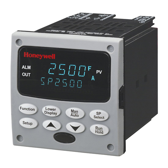
Page 13: Figure 1-1 Udc2500 Operator Interface
Introduction Figure 1-1 UDC2500 Operator Interface UDC2500 Universal Digital Limit ControllerProduct Manual... -
Page 14: Function Of Keys
RESET This function does not function on the Limit Controller SELECT • Acknowledges a latched alarm 1. HOLD • Acknowledges Diagnostic Messages. • Increases the selected parameter value. • Decreases the selected parameter value. UDC2500 Universal Digital Limit ControllerProduct Manual... -
Page 15: Process Instrument Explorer Software
PC, a Desktop or a laptop computer. · • Create/edit configurations live, just connect software to controller via comm port.· • Create/edit configurations offline and download to controller later via comm. port.· • Port types available on every UDC2500:· o infrared,· o RS 485, o Ethernet.·... -
Page 16: Figure 1-3 Depiction Of Infrared Communications
You can now communicate. After 4 minutes, the port will be shut down again. Also, in the Communications Group “IR ENABLE” may be disabled to prohibit IR communications. Figure 1-3 Depiction of infrared communications UDC2500 Universal Digital Limit ControllerProduct Manual... -
Page 17: Ce Conformity (Europe)
WARNING If this equipment is used in a manner not specified by the manufacturer, the protection provided by the equipment may be impaired. UDC2500 Universal Digital Limit ControllerProduct Manual... -
Page 19: Installation
2 Installation 2.1 Overview Introduction Installation of the UDC2500 consists of mounting and wiring the controller according to the instructions given in this section. Read the pre-installation information, check the model number interpretation (Subsection 2.3), and become familiar with your model selections, then proceed with installation. -
Page 20: Condensed Specifications
• Check that the model number shown on the inside of the case agrees with what you have ordered. 2.2 Condensed Specifications Honeywell recommends that you review and adhere to the operating limits listed in Table 2-1 when you install your controller. Table 2-1 Condensed Specifications... - Page 21 When applying power to more than one instrument, make sure that sufficient power is supplied. Otherwise, the instruments may not start up normally due to voltage drop from the inrush current. Weight 3 lbs. (1.3 kg) Environmental and Operating Conditions UDC2500 Universal Digital Limit ControllerProduct Manual...
- Page 22 60 ± 0.2 59 to 61 58 to 62 * The maximum moisture rating only applies up to 40 °C (104 °F). For higher temperatures, the RH specification is derated to maintain constant moisture content. UDC2500 Universal Digital Limit ControllerProduct Manual...
-
Page 23: Model Number Interpretation
Introduction Write your controller’s model number in the spaces provided below and circle the corresponding items in each table. This information will also be useful when you wire your controller. KEY NUMBER - UDC2500 Single Loop Controller Description Selection Availability... -
Page 24: Figure 2-1 Model Number Interpretation
2. FM approved units are restricted to TC and RTD type inputs. 3. UL listed for regulatory use only. _ L _ Input 2 Not Available with Limit Model Figure 2-1 Model Number Interpretation UDC2500 Universal Digital Limit ControllerProduct Manual... -
Page 25: Limit And Alarm Relay Contact Information
Table 2-3 Alarm Relay Contact Information Unit Alarm Relay Variable NOT in Alarm State Variable in Alarm State Power Wiring Relay Indicators Relay Indicators Contact Contact N.O. Open Open N.C. Closed Closed N.O. Closed Open N.C. Open Closed UDC2500 Universal Digital Limit ControllerProduct Manual... -
Page 26: Mounting
108,6 92,0 + 0,8 3,57 4,28 - 0,00 Panel 3,62 + 0,03 Cutout -0,00 92,0 + 0,8 113,1 - 0,00 4,45 17,9 3,62 + 0,03 0,70 -0,00 Figure 2-2 Mounting Dimensions (not to scale) UDC2500 Universal Digital Limit ControllerProduct Manual... -
Page 27: Table 2-4 Mounting Procedure
For water-protected installations, install four screws with washers into the four recessed areas in the corners of the bezel (Figure 2-3). Push the point of the screw through the center piercing the elastomeric material and then tighten screws to 5 lb-in (56 N•cm). UDC2500 Universal Digital Limit ControllerProduct Manual... -
Page 28: Wiring
Control/Alarm circuits) shall be separated from HAZARDOUS LIVE (>30 Vac, 42.4 Vpeak, or 60 Vdc) wiring per Permissible Wiring Bundling, Table 2-5. Electrical Noise Precautions Electrical noise is composed of unabated electrical signals which produce undesirable effects in measurements and control circuits. UDC2500 Universal Digital Limit ControllerProduct Manual... -
Page 29: Table 2-5 Permissible Wiring Bundling
• 4-20 mA output signal wiring Digital input signals • Low voltage alarm relay output wiring • Low voltage wiring to solid state type control circuits • Low voltage wiring to open collector type control circuits UDC2500 Universal Digital Limit ControllerProduct Manual... -
Page 30: Wiring Diagrams
See Figure 2-5 through 2-14 L2/N Used Outputs 3 and 4 Terminals See Figures 2-8 through 2-14 Input #1 Terminals See Figure 2-6 Communications Terminals See Figures 2-15 and 2-16 xxxx Figure 2-4 Composite Wiring Diagram UDC2500 Universal Digital Limit ControllerProduct Manual... -
Page 31: Figure 2-5 Mains Power Supply
CAUTION Applying 90-264 Vac to an instrument rated for 24 Vac/dc will severely damage the instrument and is a fire and smoke hazard. xxxx Figure 2-5 Mains Power Supply UDC2500 Universal Digital Limit ControllerProduct Manual... -
Page 32: Figure 2-6 Input 1 Connections
“NOFS” and use the burnout current from the other instrument to also drive this controller. xxxx Figure 2-6 Input 1 Connections UDC2500 Universal Digital Limit ControllerProduct Manual... -
Page 33: Figure 2-7 Electromechanical Relay Output
Electromechanical relays are rated at 5 Amps @120 Vac or 30 Vdc and 2.5 Amps at 240 Vac. Customer should size fuses accordingly. Use Fast Blo fuses only. xxxxx Figure 2-8 Solid State Relay Output UDC2500 Universal Digital Limit ControllerProduct Manual... -
Page 34: Figure 2-9 Open Collector Output
120 OHMS ON LAST LEG 1 Do not run the communications lines in the same conduit as AC power. xxxx 2 Use shielded twisted pair cables (Belden 9271 Twinax or equivalent). Figure 2-10 RS-422/485 Communications Option Connections UDC2500 Universal Digital Limit ControllerProduct Manual... -
Page 35: Figure 2-11 Ethernet Communications Option Connections
Digital Load Input #1 0 - 1000 Ω Connect shield to ground at one Connect shield end only. to ground at one end only. xxxx Figure 2-12 Auxiliary Output and Digital Inputs Option Connections UDC2500 Universal Digital Limit ControllerProduct Manual... -
Page 36: Figure 2-14 Transmitter Power For 4-20 Ma - 2 Wire Transmitter Using Auxiliary Output
If necessary, install a zener diode here to reduce voltage at the transmitter. A 1N4733 will reduce the voltage at the transmitter to approximately 25 Vdc. Figure 2-14 Transmitter Power for 4-20 mA — 2 Wire Transmitter Using Auxiliary Output UDC2500 Universal Digital Limit ControllerProduct Manual... -
Page 37: Limit Control Application Diagram
POWER POWER LOAD LOAD The Limit Controller CANNOT protect The Limit Controller CAN protect against a failure of the Control relay against a failure of the Control relay Figure 2-15 Limit Controller Application Diagram UDC2500 Universal Digital Limit ControllerProduct Manual... -
Page 38: Configuration
3.5 Limit Set Up Group 3.6 Input 1 Set Up Group 3.7 Options Set Up Group 3.8 Communications Set Up Group 3.9 Alarms Set Up Group 3.10 Display Set Up Group 3.11 Configuration Record Sheet UDC2500 Universal Digital Limit ControllerProduct Manual... -
Page 39: Configuration Prompt Hierarchy
SDENAB SHDTIM BAUD TX DLY WS FLT UNITS LOOPBK ALARMS A1S1TY A1S1VA A1S1HL A1S1TY A1S1VA A1S1HL A1S1TY A1S1VA A1S1HL A1S1TY A1S1VA A1S1HL ALHYST ALARM1 BLOCK DIAGAL DISPLY DECMAL UNITS FREQ STATUS VERSON FAILSF TESTS UDC2500 Universal Digital Limit ControllerProduct Manual... -
Page 40: Configuration Procedure
It stores any changes you have made. If you do not press any keys for 30 seconds, the controller times out and reverts to the mode and display used prior to entry into Set Up mode. UDC2500 Universal Digital Limit ControllerProduct Manual... -
Page 41: Lock Set Up Group
CAL - all parameters are read/write except Calibration CONF CONF – configuration parameters are Read Only; no writes permitted +SP – Only the Lockout group is available for read/write. Setpoint value is Read Only. UDC2500 Universal Digital Limit ControllerProduct Manual... -
Page 42: Limit Set Up Group
0 % to 100 % of input in prevents the setpoint from going below the engineering units value selected here. The setting must be equal to or greater than the lower range of the input. UDC2500 Universal Digital Limit ControllerProduct Manual... -
Page 43: Input 1 Set Up Group
100m—0 to 100 Millivolts * 0-5—0 to 5 Volts * 1-5—1 to 5 Volts * 0-10 0-10—0 to 10 Volts * TDIF TDIF—Thermocouple Differential * * These input types are not available on FM Models. UDC2500 Universal Digital Limit ControllerProduct Manual... - Page 44 Set IN1 LO display value to 0 Then 20 mA = 250 Liters/Minute and 4 mA = 0 Liters/Minute ATTENTION The range of the Limit setpoint will be limited by the range of units selected here. UDC2500 Universal Digital Limit ControllerProduct Manual...
- Page 45 Input 1 signal developed by the Burnout circuitry. DOWN DOWNSCALE BURNOUT will force the Input 1 signal to the lower range value when the sensor fails. Diagnostic message IN1 FAIL intermittently flashed on the lower display. UDC2500 Universal Digital Limit ControllerProduct Manual...
- Page 46 Radiamatic input signal that is the ratio of the actual energy emitted from the target to the energy which would be emitted if the target were a perfect radiator. Available only for Radiamatic inputs. UDC2500 Universal Digital Limit ControllerProduct Manual...
-
Page 47: Options Group
This value represents the deviation level that will produce 20 mA (100 %) output. Zero deviation will produce a center scale (12 mA or 50 %) output. A negative deviation equal UDC2500 Universal Digital Limit ControllerProduct Manual... - Page 48 EXTERNAL RESET (DIGITAL INPUT) — resets the latching relay on contact closure. DIS – Disable ENAB ENAB – Enable UDC2500 Universal Digital Limit ControllerProduct Manual...
-
Page 49: Communications Group
This parameter is also used for the IR communications link. COMSTA COMMUNICATIONS SELECTION DISABLE—Disables the communications option. MODB MODBUS—Allows Modbus RTU communication prompts. IRENAB INFRARED COMMUNICATIONS – EnAB Enables/Disables the IR Port. UDC2500 Universal Digital Limit ControllerProduct Manual... - Page 50 LAST LAST—SAME MODE AND OUTPUT—The controller will return to the same mode (manual or automatic) at the same output level that it had before shed. UDC2500 Universal Digital Limit ControllerProduct Manual...
- Page 51 ATTENTION The instrument does not have to be connected to the external communications link in order to perform this test. If it is connected, only UDC2500 Universal Digital Limit ControllerProduct Manual...
- Page 52 Selection or Range of Parameter Lower Display Setting Definition Upper Display one instrument should run the loopback test at a time. The host computer should not be transmitting on the link while the loopback test is active. UDC2500 Universal Digital Limit ControllerProduct Manual...
-
Page 53: Alarms Set Up Group
THERMOCOUPLE WARNING (NOTE 1) TC F THERMOCOUPLE FAILING (NOTE 2) ATTENTION NOTE 1. Thermocouple Warning means that the instrument has detected that the Thermocouple Input is starting to fail. Not valid for input types other than Thermocouple. UDC2500 Universal Digital Limit ControllerProduct Manual... - Page 54 Value in engineering units A2S1VA value at which you want the alarm type chosen in prompt A2S1TYPE to actuate. The details are the same as A1S1 VAL. HIGH A2S1HL ALARM 2 SETPOINT 1 STATE—Same as A1S1HL. UDC2500 Universal Digital Limit ControllerProduct Manual...
- Page 55 1 can be configured to be Latching or Non-latching. NO LAT—Non-latching NO LAT LATCH—Latching LATCH ATTENTION When configured for latching, the alarm will stay active after the alarm condition ends until the RUN/HOLD key is pressed. UDC2500 Universal Digital Limit ControllerProduct Manual...
- Page 56 3.5 mA, then an Alarm is activated. This configuration is in addition to whatever was selected for AxSxTYPE. DISABLE—Disables Diagnostic Alarm AL 1 ALARM 1—Alarm 1 is diagnostic alarm AL 2 ALARM 2—Alarm 2 is diagnostic alarm UDC2500 Universal Digital Limit ControllerProduct Manual...
-
Page 57: Display Set Up Group
+24 Vdc, this configuration should be set to the AC line frequency used to produce the +24 Vdc supply. Incorrect setting of this parameter can cause normal mode noise problems in the input readings. UDC2500 Universal Digital Limit ControllerProduct Manual... -
Page 58: Configuration Record Sheet
_______ OPTIONS AUXOUT _______ A2S2HL _______ HIGH 0 PCT _______ ALHYST _______ 100 PCT _______ ALARM1 _______ CRANGE _______ 4-20 BLOCK _______ DIGIN1 _______ DIAGAL _______ DECML _______ NONE DISPLY UNITS _______ FREQ _______ UDC2500 Universal Digital Limit ControllerProduct Manual... -
Page 59: Operating The Limit Controller
The following topics are covered in this section. TOPIC See Page 4.1 Overview 4.2 Operator Interface 4.3 Entering A Security Code 4.4 Lockout Feature 4.5 Monitoring The Limit Controller 4.6 How to Operate Your Limit Controller 4.7 Alarm Setpoints UDC2500 Universal Digital Limit ControllerProduct Manual... -
Page 60: Operator Interface
NONE. Thereafter, that selected number must be used to change the lockout level from something other than NONE. Write the number on the Configuration Record Sheet in the configuration section so you will have a permanent record. UDC2500 Universal Digital Limit ControllerProduct Manual... -
Page 61: Lockout Feature
This will be your security code. 4.4 Lockout Feature Introduction The lockout feature in the UDC2500 is used to inhibit changes (via keyboard) of certain functions or parameters by unauthorized personnel. Lockout levels There are different levels of Lockout depending on the level of security required. These levels are: •... -
Page 62: Monitoring Your Limit Controller
Timing out from lower display The normal variable display will automatically return in the upper display if the [LOWER key is not pressed for 30 seconds. DISPLAY] UDC2500 Universal Digital Limit ControllerProduct Manual... -
Page 63: Table 4-3 Error Messages
(blinking). The PV is indicated in the upper display. This will continue until the Out-of- Limit condition exists and you reset the latching relay using the [MAN-AUTO RESET] or through the Optional External Reset feature. The Limit Relay cannot be reset while a Limit condition exists. UDC2500 Universal Digital Limit ControllerProduct Manual... -
Page 64: Operating Your Limit Controller
Refer to Section 3 - Configuration, subsection 3.4 Limit Parameters Set Up Group under SET UP prompt “LIMIT” and make your selection at FUNCTION prompt “POWRUP.” UDC2500 Universal Digital Limit ControllerProduct Manual... - Page 65 Set the SP, using the Up & Down arrow keys, to the desired Limit Setpoint Setpoint Store the limit Press the "Lower Display" to store the value. LOWER setpoint DISPLAY If the display Press the Auto-Man/ Reset key. flashes "Limit" RESET UDC2500 Universal Digital Limit ControllerProduct Manual...
-
Page 66: Table 4-4 Using Contact Input Option
Upper Display = SET Lower Display = OPTIONS Access the Until you see: FUNCTION External Reset Upper Display = ENAB Prompt Lower Display = DIGIN1 Change a value To select ENAB in the upper display UDC2500 Universal Digital Limit ControllerProduct Manual... -
Page 67: Alarm Setpoints
DE (Deviation) value = within Input 1 Span PV (Process variable) value = Within Input 1 range Change a value To change any alarm setpoint value in the upper display Return to Normal LOWER Display DISPLAY UDC2500 Universal Digital Limit ControllerProduct Manual... -
Page 68: Input Calibration
Introduction This section describes the field calibration procedures for Input 1. • All input actuations in every UDC2500 controller are fully factory-calibrated and are ready for configuration by the user. • Field Calibration can improve the accuracy of the Controller if necessary for a particular application. -
Page 69: Minimum And Maximum Range Values
Nicrosil-Nisil (Nic) 0 to 2372 –18 to 1300 –0.461 mV 47.513 mV 0 to 1472 –18 to 800 -0.461 mV 28.455 mV Nic (low) 0 to 3100 –18 to 1704 –0.090 mV 20.281 mV UDC2500 Universal Digital Limit ControllerProduct Manual... - Page 70 Field Calibration of the input, with the range value limits being –4 mV to +16 mV for the zero and span values. ** The range values for Radiamatic Type RI are customer configurable. UDC2500 Universal Digital Limit ControllerProduct Manual...
-
Page 71: Preliminary Information
A calibrating device with at least ± 0.02 % accuracy for use as a Millivolt, Volts, and signal source. Radiamatic • Two insulated copper leads for connecting the calibrator to the controller. • Place current source at zero before switching ON. UDC2500 Universal Digital Limit ControllerProduct Manual... -
Page 72: Input 1 Set Up Wiring
Connect the thermocouple extension wires to the terminals for Input #1. See Figure 5-2. Millivolt Source Ice Bath Thermocouple Copper Leads Extension Wire Figure 5-2 Wiring Connections for Thermocouple Inputs Using an Ice Bath UDC2500 Universal Digital Limit ControllerProduct Manual... -
Page 73: Table 5-4 Set Up Wiring Procedure For Thermocouple Inputs Using Thermocouple Source
Step Action Connect the copper leads from the calibrator to the Input #1 terminals as shown in Figure 5-4. Decade Resistance Copper Leads Equal Length Figure 5-4 Wiring Connections for RTD (Resistance Thermometer Device) UDC2500 Universal Digital Limit ControllerProduct Manual... -
Page 74: Table 5-6 Set Up Wiring Procedure For Radiamatic, Millivolts, Volts Or Thermocouple Differential Inputs
For Radiamatic inputs only, set Emissivity value to 1.0. See Subsection 3.6 – Configuration Set Up prompt INPUT1, function prompt EMISS. Millivolt or Volt Source Figure 5-5 Wiring Connections for Radiamatic, Millivolts, Volts or Thermocouple Differential (Except 0 to 10 Volts) UDC2500 Universal Digital Limit ControllerProduct Manual... -
Page 75: Table 5-7 Set Up Wiring Procedure For 0 To 10 Volts
Place current source at zero before switching on. Do not switch current source ON/OFF while connected to the instrument. Milliampere 250 ohms Source Figure 5-7 Wiring Connections for 0 to 20 mA or 4 to 20 mA Inputs UDC2500 Universal Digital Limit ControllerProduct Manual... -
Page 76: Input 1 Calibration Procedure
See Table 5-1 for Voltage, Degrees, or Resistance equivalents for 0 % range values. • Wait 15 seconds, then go to the next step. Calibrate 100 % You will see: FUNCTION Upper Display = APLY UDC2500 Universal Digital Limit ControllerProduct Manual... -
Page 77: Restore Factory Calibration
“Factory Calibration” for a given input actuation type by simply changing the actuation type to another type and then changing it back to the original type. Refer to Table 5-10 Restore Factory Calibration for procedure. UDC2500 Universal Digital Limit ControllerProduct Manual... -
Page 78: Table 5-10 Restore Factory Calibration
Normal operating mode. Return to Normal LOWER Operation DISPLAY The factory calibration will be restored. If the problem is not corrected, contact the Honeywell Technical Assistance Center. 1-800-423-9883 USA and Canada UDC2500 Universal Digital Limit ControllerProduct Manual... -
Page 79: Output Calibration
You will need a calibrating device with whatever accuracy is required, capable of measuring 0 to 20 mA. Calibrator Connections Refer to Figure 6-1 and wire the controller according to the procedure given in Table 6-1. UDC2500 Universal Digital Limit ControllerProduct Manual... -
Page 80: Table 6-1 Set Up Wiring Procedure For Auxiliary Output
Tag and disconnect the field wiring, at the rear of the controller, from terminals 12 (+) and 13 (–). See Figure 6-1. Connect a milliammeter across these terminals. Milliammeter xxxx Figure 6-1 Wiring Connections for Calibrating Auxiliary Output UDC2500 Universal Digital Limit ControllerProduct Manual... -
Page 81: Table 6-2 Auxiliary Output Calibration Procedure
Upper Display = A Value Lower Display = SPNVAL until the desired 100 % output is read on the milliammeter. Exit the The controller stores the span value. FUNCTION Calibration Mode To exit the calibration mode. LOWER DISPLAY UDC2500 Universal Digital Limit ControllerProduct Manual... -
Page 82: Troubleshooting/Service
• Keyboard Failure Restore Factory Configuration Installation related problems Read the Installation section in this manual to make sure the UDC2500 has been properly installed. The installation section provides information on protection against electrical UDC2500 Universal Digital Limit ControllerProduct Manual... -
Page 83: Troubleshooting Aids
An engineer will discuss your problem with you. Please have your complete model number, serial number, and Software version available. The model and serial numbers can be found on the chassis nameplate. The software version can be viewed under Setup Group “Status.” See Table 7-1. UDC2500 Universal Digital Limit ControllerProduct Manual... -
Page 84: Table 7-1 Procedure For Identifying The Software Version
Do not return your controller without authorization from Honeywell’s Technical Assistance Center or until the replacement has been received. For a list of frequently asked questions and their answers, dial Honeywell’s Faxback 24 hour Service: 1-888-423-9883 USA Or check out Honeywell’s web site at... -
Page 85: Power-Up Tests
Set Up Group Read the test FUNCTION You will see: results Upper Display = NO or YES YES indicates a failure Lower Display = FAILSAFE FUNCTION Upper Display = PASS or FAIL Lower Display = TEST UDC2500 Universal Digital Limit ControllerProduct Manual... -
Page 86: Background Tests
Troubleshooting/Service Background Tests Introduction The UDC2500 performs ongoing background tests to verify data and memory integrity. If there is a malfunction, a diagnostic message will be displayed (blinking) in the lower display. In the case of simultaneous malfunctions, the messages will appear in sequence in the lower display. - Page 87 User should consider replacing the thermocouple as soon as possible. OUT2FL Auxiliary Output is less than 3.5 mA. The auxiliary output is open circuit. Check the field wiring. See Procedure #9. UDC2500 Universal Digital Limit ControllerProduct Manual...
-
Page 88: Controller Failure Symptoms
This may lead to a different troubleshooting procedure. If the symptom still persists, refer to the installation section in this manual to ensure proper installation and proper use of the controller in your system. UDC2500 Universal Digital Limit ControllerProduct Manual... -
Page 89: Troubleshooting Procedures
You will need the following equipment in order to troubleshoot the symptoms listed in the tables that follow: • Multimeter – Capable of measuring millivolts, milliamps and resistance. • Calibration sources – T/C, mV, Volt, etc. UDC2500 Universal Digital Limit ControllerProduct Manual... -
Page 90: Table 7-5 Troubleshooting Power Failure Symptoms
Check the system for Brown- Refer to Section 2 - Installation. outs, heavy load switching, etc., and conformance to installation instructions. Change Power board. Installation instructions supplied with new board. UDC2500 Universal Digital Limit ControllerProduct Manual... -
Page 91: Table 7-6 Troubleshooting Latching Output Relay Failure
Refer to Section 2 - Installation for relay contact information. Change the relay and/or the Installation instructions supplied with the current output board. new relay or board. Change MCU board. Installation instructions supplied with the new board. UDC2500 Universal Digital Limit ControllerProduct Manual... -
Page 92: Table 7-8 Troubleshooting A Keyboard Failure
TRY ALL Press each key. If it works, the key name will appear in the lower display. Replace the display/keyboard if any Refer to “Parts Replacement keys are shorted out. Procedures ” in this section. UDC2500 Universal Digital Limit ControllerProduct Manual... -
Page 93: Table 7-9 Troubleshooting A Rs-485 Communications Failure
Lower Display Press [FUNCTION] until you see: Upper Display DISABLE Lower Display LOOPBACK Press you will see: Upper Display ENABLE Lower Display LOOPBACK The test will run until the operator disables it here. UDC2500 Universal Digital Limit ControllerProduct Manual... -
Page 94: Table 7-10 Troubleshooting Auxiliary Output Failure
Use a DC milliammeter at the rear terminals to verify the output. Recalibrate the Auxiliary output. Refer to Section 6 - Output Calibration for details. Change Auxiliary Output board. Installation instructions provided with new board. Change Controller UDC2500 Universal Digital Limit ControllerProduct Manual... -
Page 95: Restoring Factory Configuration
When the instrument finishes the restore operation, it automatically resets itself and restarts in the product mode. The instrument configuration will now be the same as it was when the instrument left the factory and all user-entered configurations since that time have been overwritten. UDC2500 Universal Digital Limit ControllerProduct Manual... -
Page 96: Parts List
Exploded View Introduction Figure 8-1 is an exploded view of the UDC2500 Controller. Each part is labeled with a key number. The part numbers are listed by key number in Table 8-1. Parts not shown are listed in Table 8-2. -
Page 97: Table 8-1 Parts Identification
• Solid State Relay 30756725-501 Table 8-2 Parts Not Shown Part Number Description 30731996-506 4-20 mA Input Resistor Assembly (250 ohm) 30754465-501 0-10 Volt Input Resistor Assembly (100K pair) 51452763-501 Mounting Kits (12 brackets) UDC2500 Universal Digital Limit ControllerProduct Manual... -
Page 98: Removing The Chassis
Pry just enough to release it, otherwise you’ll bend or break the tab. If you break or bend the tab and can’t reattach the front snugly, you’ll need to reattach the front using the 4 NEMA4 screws provided. See Figure 2-3 on page 17. UDC2500 Universal Digital Limit ControllerProduct Manual... -
Page 99: Modbus
Modbus 9 Modbus 9.1 Overview This section is not defined at this time. UDC2500 Universal Digital Limit ControllerProduct Manual... -
Page 100: Ethernet Tcp/Ip
Ethernet TCP/IP 10 Ethernet TCP/IP 10.1 Overview Ethernet parameters can only be configured via the Process Instrument Explorer software. UDC2500 Universal Digital Limit ControllerProduct Manual... -
Page 101: Further Information
Refer to Honeywell document 51-52-25-121 MODBUS Messaging on TCP/IP Implementation Guide. 11.2 How to Apply Digital Instrumentation in Severe Electrical Noise Environments Refer to Honeywell document 51-52-05-01 How to Apply Digital Instrumentation in Severe Electrical Noise Environments. UDC2500 Universal Digital Limit ControllerProduct Manual... - Page 102 Function Prompts, 29 Set Up Wiring Procedure for Auxiliary Output, 70 High and Low Limit Indication, 53 software version number, 74 HIGH SETPOINT LIMIT, 32 Specifications, 10 Input 1 actuation type, 33 Status Tests, 75 UDC2500 Universal Digital Limit ControllerProduct Manual...
- Page 103 Millivolts, or Volts (Except 0 to 10 Volts), 64, 65 Troubleshooting Aids, 73 Wiring Connections for RTD (Resistance troubleshooting procedures, 79 Thermometer Device), 63 Troubleshooting/Service, 72 Wiring Diagrams, 20 UDC2300 Limit Controllers, 1 Wiring the Controller, 20 Viewing the operating parameters, 52 UDC2500 Universal Digital Limit ControllerProduct Manual...
- Page 104 820 07 BRATISLAVA 27 BULGARIA H-1133 BUDAPEST Tel. : 351 1 424 50 00 SLOVAKIA Tel : 359-791512/ HUNGARY Tel. : 421 7 52 47 794027/ 792198 Tel. : 36 1 451 43 00 400/425 UDC2500 Universal Digital Limit ControllerProduct Manual...
- Page 108 Industrial Measurement and Control Honeywell 1100 Virginia Drive Fort Washington, PA 19034 www.honeywell.com/imc 51-52-25-118 Rev. 1 0504 Printed in USA...