Honeywell UDC3300 User Manual
Universal digital controller
Hide thumbs
Also See for UDC3300:
- Product manual (294 pages) ,
- User manual (118 pages) ,
- Instruction manual (4 pages)
Table of Contents
Advertisement
Quick Links
Advertisement
Table of Contents

Related Manuals for Honeywell UDC3300


Summary of Contents for Honeywell UDC3300
- Page 1 UDC3300 Basic Model: DC330B User Manual 51-52-25-78 5/00 Sensing and Control...
- Page 2 However, we assume no responsibility for its use. While we provide application assistance personally, through our literature and the Honeywell web site, it is up to the customer to determine the suitability of the product in the application. Sensing and Control...
-
Page 3: About This Document
UDC3300 product manual (request document number 51-52-25-55). Contacts World Wide Web The following lists Honeywell’s World Wide Web sites that will be of interest to our customers. Honeywell Organization WWW Address (URL) Corporate http://www.honeywell.com... - Page 4 Chassis Ground. Identifies a connection to the chassis or frame of the equipment shall be bonded to Protective Earth at the source of supply in accordance with national and local electrical code requirements. UDC3300 Basic Model: DC330B User Manual 5/00...
-
Page 5: Table Of Contents
4.1 How to Power Up the Controller ...................39 4.2 Monitoring Your Controller ...................39 4.3 Start-up Procedure.......................42 4.4 Operating Modes......................43 4.5 Setpoints ........................43 4.6 Using Two Sets of Tuning Constants ................44 4.7 Alarm Setpoints......................46 5/00 UDC3300 Basic Model: DC330B User Manual... - Page 6 APPENDIX A – ENVIRONMENTAL AND OPERATING CONDITIONS ....63 APPENDIX B – MODEL SELECTION GUIDE.............65 APPENDIX C – CONFIGURATION RECORD SHEET ........67 APPENDIX D – POSITION PROPORTIONAL CALIBRATION ......69 9.1 Position Proportional Control Output Calibration ............69 APPENDIX E – INPUT RANGES.................73 UDC3300 Basic Model: DC330B User Manual 5/00...
- Page 7 Table 4-15 Procedure to Enter a Security Code ___________________________________ 52 Table 5-1 Procedure for Running a Setpoint Ramp_________________________________ 54 Table 5-2 Program Contents __________________________________________________ 56 Table 5-3 Run/Monitor Functions_______________________________________________ 60 Table 9-1 Calibration Procedure _______________________________________________ 70 5/00 UDC3300 Basic Model: DC330B User Manual...
- Page 8 Figure 2-17 Transmitter Power for 4-20 mA 2-wire Transmitter Using Auxiliary Output—Model DC330X-XX-2XX or DC330X-XX-5XX ____________________ 16 Figure 3-1 Prompt Hierarchy __________________________________________________ 19 Figure 5-1 Ramp/Soak Profile Example _________________________________________ 58 Figure 5-2 Program Record Sheet______________________________________________ 59 viii UDC3300 Basic Model: DC330B User Manual 5/00...
-
Page 9: Introduction
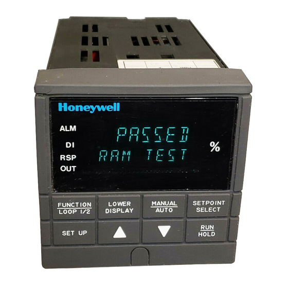
• If PV is equal to or greater than LOOP 1/2 DISPLAY SELECT AUTO ±10% deviation, the center bar Keys - See Table 1-1 plus all ten deviation bars will light. SET UP HOLD Figure 1-1 Operator Interface Displays and Indicators 5/00 UDC3300 Basic Model: DC330B User Manual... -
Page 10: Function Keys
Hold key down to cycle through configured setpoints. SELECT Alternate action switch initiates or holds the Setpoint Ramp or Setpoint HOLD Program. Acknowledges a latched alarm 1. Increases the selected parameter value. Decreases the selected parameter value. UDC3300 Basic Model: DC330B User Manual 5/00... -
Page 11: Installation
FUNCTION LOWER SETPOINT AUTO L1/L2 DISPLAY SELECT SET UP HOLD Max Panel 2.4 with optional .945 Thickness .093 Max (2) rear cover .394 90.7 3.57 21.6 147.3 .850 24152 5.82 Figure 2-1 Dimensions 5/00 UDC3300 Basic Model: DC330B User Manual... -
Page 12: Wiring
National and local electrical codes. To minimize electrical noise and transients that may adversely affect the system, supplementary bonding of the controller enclosure to a local ground, using a No. 12 (4 mm ) copper conductor, is recommended. UDC3300 Basic Model: DC330B User Manual 5/00... -
Page 13: Table 2-1 Permissible Wiring Bundling
• 4-20 mA output signal wiring • Slidewire feedback circuit wiring • Digital input signals • Communications • Low voltage alarm relay output wiring • Low voltage wiring to solid state type control circuits 5/00 UDC3300 Basic Model: DC330B User Manual... -
Page 14: Figure 2-3 Composite Wiring Diagram
(Do not use for See Figure 2-13 Transmitters Communications shield) • Using Alarm 2 Output See Figure 2-16 Communications Terminals • Using Auxiliary Output See Figure 2-15 See Figure 2-17 Figure 2-3 Composite Wiring Diagram UDC3300 Basic Model: DC330B User Manual 5/00... -
Page 15: Figure 2-4 Line Voltage Wiring
Provide a switch and non-time delay (North America), quick-acting, high breaking capacity, Type F (Europe), 1/2A, 250V fuse(s) or circuit-breaker for 90-264V; or 1A, 125V fuse or circuit breaker for 24 Vac/dc operation, as part of the installation. Figure 2-4 Line Voltage Wiring 5/00 UDC3300 Basic Model: DC330B User Manual... -
Page 16: Figure 2-5 Input #1/#2 Connections
Input 1 as the 100K 0–10 Xmitter option, use Input 1 as the Carbon Probe input. Volt Carbon Probe input. source Power – 100K – – – Supply Figure 2-5 Input #1/#2 Connections UDC3300 Basic Model: DC330B User Manual 5/00... -
Page 17: Table 2-2 Input 2 Jumper Selections
Electromechanical relays are rated at 5 Amps @120 Vac or 30 Vdc and 2.5 Amps at 240 Vac. Customer should size fuses accordingly. Use Fast Blo fuses only. Figure 2-6 Electromechanical Relay Output – Model DC330X-EE-XXX 5/00 UDC3300 Basic Model: DC330B User Manual... -
Page 18: Figure 2-7 Solid State (Ss) Relay Output - Model Dc33X-Aa-Xx
55°C. Customer Black should size fuses Output 1 accordingly. Use – White Fast Blo fuses – only. Output 2 – Solid State Relay Green Figure 2-8 10-amp SS External Relay Output — Model DC330X-SS-XX UDC3300 Basic Model: DC330B User Manual 5/00... -
Page 19: Figure 2-9 Open Collector Output - Model Dc330X-Tt-Xxx
Electromechanical relays are rated at 5 Amps @120 Vac or 30 Vdc and 2.5 Amps at 240 Vac. Customer should size fuses accordingly. Use Fast Blo fuses only. Figure 2-9 Open Collector Output — Model DC330X-TT-XXX 5/00 UDC3300 Basic Model: DC330B User Manual... -
Page 20: Figure 2-10 Current Output Current/Time Duplex, Time/Current Duplex, Position Proportional Or Three Position Step Control
Electromechanical relays are rated at 5 Amps @120 Vac or 2.5 Amps at 240 Vac. Customer should size fuses accordingly. Use Fast Blo fuses only. All current outputs are isolated from each other, case ground, and all inputs. 24160 Figure 2-11 Auxiliary Output and Three-Relay Output UDC3300 Basic Model: DC330B User Manual 5/00... -
Page 21: Figure 2-12 Position Proportional Output Or Three Position Step-Models Dc330X-Ee-Xxx-X2, Dc330X-Aa-Xxx-X2
Electrical noise suppression may be required. Slidewire input is not required for Three Position Step control but can be used for motor position indication. Figure 2-12 Position Proportional Output or Three Position Step— Models DC330X-EE-XXX-X2, DC330X-AA-XXX-X2 5/00 UDC3300 Basic Model: DC330B User Manual... -
Page 22: Figure 2-13 Auxiliary Output Connections- Models Dc330X-Xx-2Xx
Figure 2-13 Auxiliary Output Connections— Models DC330X-XX-2XX, DC330X-XX-5XX Digital Inputs Digital Input Switch #1 Digital Input Switch #2 Connect shield to ground at one end only Switch Common Figure 2-14 Digital Inputs Connections—Model DC330X-XX-XX3 UDC3300 Basic Model: DC330B User Manual 5/00... -
Page 23: Figure 2-15 Rs422/485/Ascii Or Modbus Communications Option Connections
RX– TX– Resistor To Other Use shielded twisted pair Communication cables (Belden 9271 Instruments 120 Ohm Resistor Twinax or equivalent) (maximum 31) on Last Leg Figure 2-15 RS422/485/ASCII or Modbus Communications Option Connections 5/00 UDC3300 Basic Model: DC330B User Manual... -
Page 24: Dc330X-Xx-5Xx
2-wire ZERO VAL = 4095 Zener Diode Transmitter SPAN VAL = 4095 – – – 250 ohm resistor Figure 2-17 Transmitter Power for 4-20 mA 2-wire Transmitter Using Auxiliary Output—Model DC330X-XX-2XX or DC330X-XX-5XX UDC3300 Basic Model: DC330B User Manual 5/00... -
Page 25: Table 2-3 Control Relay Contact Information
Table 2-4 Alarm Relay Contact Information Variable Variable Alarm NOT in Alarm State in Alarm State Unit Relay Power Relay Relay Wiring Indicators Indicators Contact Contact N.O. Open Open N.C. Closed Closed N.O. Closed Open N.C. Open Closed 5/00 UDC3300 Basic Model: DC330B User Manual... - Page 26 Installation UDC3300 Basic Model: DC330B User Manual 5/00...
-
Page 27: Configuration
CONT ALG TIMER PERIOD START L DISP INP ALG1 MATH K CALC HI CALC LO ALG1 INA ALG1 INB ALG1 INC ALG1BIAS PCT CO OUT ALG OUT ALG 4-20 RNG RLYSTATE RLY TYPE 5/00 UDC3300 Basic Model: DC330B User Manual... - Page 28 A2S1 EV A2S2 H L A2S2 EV AL HYST ALM OUT1 BLOCK DISPLAY DECIMAL TEMPUNIT PWR FREQ RATIO 2 LANGUAGE CALIB USED FOR FIELD CALIBRATION STATUS VERSON FAILSAFE RAM TEST CONFTEST CALTEST FACT CRC UDC3300 Basic Model: DC330B User Manual 5/00...
-
Page 29: Configuration Procedure
Exit Exits configuration mode and returns the controller LOWER Configuration to the same state it was in immediately preceding DISPLAY entry into the Set Up mode. It stores any changes you have made. 5/00 UDC3300 Basic Model: DC330B User Manual... -
Page 30: Loop 1 Tuning Parameters Set Up Group
0.02 to 50.00 1.00 Reset 2 in repeats/minute RSET2RPM Cycle Time (Heat) 1 to 120 CYC SEC CYC SX3 Cycle Time (Cool) 1 to 120 CYC2 SEC CYC2 SX3 Security Code 0 to 4095 SECURITY UDC3300 Basic Model: DC330B User Manual 5/00... - Page 31 Configuration Lockout NONE CALIB CALIB + CONF + VIEW Manual/Auto Key Lockout DISABL ENABLE AUTO MAN ENABLE Setpoint Select Key DISABL ENABLE SP SEL Lockout ENABLE Run/Hold Key Lockout DISABL ENABLE RUN HOLD ENABLE 5/00 UDC3300 Basic Model: DC330B User Manual...
-
Page 32: Sp Ramp, Sp Rate, Or Sp Programming Set Up Group
Always end in a soak segment (2, 4, ... 12) Engineering Units for TIME (hours.minutes) TIME RAMPUNIT Ramp Segments EU/MIN (engineering units/minute) EU/HR (engineering units/hour) Number of Program 0 to 99 recycles –– RECYCLES Recycles UDC3300 Basic Model: DC330B User Manual 5/00... - Page 33 –– SEG 3, 5, 7, 9 & 11 RAMP SEG 3, 5, 7, 9, & 11 RATE SEG 4, 6, 8, 10 & 12 SP SEG 4, 6, 8, 10 & 12 TIME 5/00 UDC3300 Basic Model: DC330B User Manual...
-
Page 34: Accutune Set Up Group
Timer Enable/Disable ENABLE DISABL DISABL Timeout Period 00:00 to 99:59 00:01 PERIOD START Start Initiation KEY (Run/Hold key) ALARM2 Lower Display Selection TI REM (time remaining) TI REM L DISP E time (elapsed time) UDC3300 Basic Model: DC330B User Manual 5/00... - Page 35 INP 1 INP 2 LP1OUT IN AL1 Percent Carbon Monoxide 0.020 to 0.350 (fractional 0.200 PCT CO percent of CO) Input Algorithm 1 Bias -999 to 9999 floating (in 0.000 ALG1BIAS engineering units) 5/00 UDC3300 Basic Model: DC330B User Manual...
-
Page 36: Output Algorithm Parameters Set Up Group
2 are both energized) Relay Cycle Time MECHAN (Cycle time in one MECHAN RLY TYPE Increments second increments) SOL ST (Cycle time in 1/3 second increments: 1 = .33 seconds, 120 = 40 seconds) UDC3300 Basic Model: DC330B User Manual 5/00... -
Page 37: Input 1 Parameters Set Up Group
Input 1 Bias –999. to 9999. BIAS IN1 (in engineering units) FILTER 1 Input 1 Filter 0 to 120 seconds Burnout Protection NONE DOWN NONE BURNOUT1 NO_FS Emissivity 0.01 to 1.00 0.00 EMISSIV1 5/00 UDC3300 Basic Model: DC330B User Manual... -
Page 38: Input 2 Parameters Set Up Group
Input 2 Bias –999. to 9999. BIAS IN2 (in engineering units) FILTER 2 Input 2 Filter 0 to 120 seconds Burnout Protection NONE DOWN NONE BURNOUT2 NO_FS EMISSIV2 Emissivity 0.01 to 1.00 0.00 UDC3300 Basic Model: DC330B User Manual 5/00... -
Page 39: Loop 1 Control Parameters Set Up Group
Control Output Direction DIRECT REVRSE ACTION REVRSE Output Change Rate ENABLE DISABL OUT RATE DISABL Does not apply to 3 Position Step Control algorithm. PCT/M UP Output Rate Up Value 0 to 9999% per minute 5/00 UDC3300 Basic Model: DC330B User Manual... - Page 40 Within the range of output limits MAN OUT for Manual Output Power-up Preset Output Within the range of output limits AUTO OUT for Automatic Output PBorGAIN Proportional Band or Gain PB PCT GAIN Units GAIN MINorRPM Reset Units UDC3300 Basic Model: DC330B User Manual 5/00...
-
Page 41: Options Set Up Group
Digital Input 1 DISABL +ToSP2 DISABL Combinations +PID2 +ToSP1 +ToDIR +RUN Digital 2 Input Selections Same as DIG IN 1 NONE DIG IN 2 DIG2 COM Digital Input 2 Same as DIG1 COM DISABL Combinations 5/00 UDC3300 Basic Model: DC330B User Manual... -
Page 42: Communications Set Up Group
Duplex Operation HALF HALF DUPLEX FULL ATTENTION • When ComSTATE = MODBUS, this selection is fixed at HALF. • When the RS422/485/Auxiliary output option board is installed, this selection is fixed at HALF. UDC3300 Basic Model: DC330B User Manual 5/00... - Page 43 Communication Units PERCNT PERCNT CSP RATO Loop 1 Computer Setpoint –20.0 to 20.0 Ratio CSP BIAS Loop 1 Computer Setpoint –999. to 9999. Bias (in engineering units) LOOPBACK Local Loop Back DISABL DISABL ENABLE 5/00 UDC3300 Basic Model: DC330B User Manual...
-
Page 44: Alarms Set Up Group
A2S2TYPE Alarm 1, Setpoint 1 State HIGH A1S1 H L HIGH SP Programming Event BEGIN A1S1 EV Alarm State for Alarm 1, Setpoint 1 Alarm 2, Setpoint 1 State A1S2 H L HIGH UDC3300 Basic Model: DC330B User Manual 5/00... - Page 45 ALM OUT1* Latching Alarm for NO LAT NO LAT Output 1 LATCH BLOCK Alarm Blocking DISABL DISABL BLOCK1 BLOCK2 BLK 12 * For CE Conformity, Performance Criteria A, Select NO LAT 5/00 UDC3300 Basic Model: DC330B User Manual...
-
Page 46: Display Parameters Set Up Group
3.16 Status Group The prompts used hare are read only. They are used to determine the reason for a controller failure. Refer to Section 9 – Troubleshooting in manual #51-52-25-55 for complete information. UDC3300 Basic Model: DC330B User Manual 5/00... -
Page 47: Operation
Press the LOWER DISPLAY key to scroll through the operating parameters listed in Table 4-1. The lower display will show only those parameters and their values that apply to your specific model and the way in which it was configured. 5/00 UDC3300 Basic Model: DC330B User Manual... -
Page 48: Table 4-1 Lower Display Key Parameter Prompts
BIAS—Displays the manual reset value for algorithm PD+MR. LIMIT CYCLE TUNING NOT RUNNING—Appears when Accutune is disabled. TUNE OFF TUNE RUN LIMIT CYCLE TUNING RUNNING—Appears when Accutune is enabled. RESET SP PROGRAM TO BEGINNING OF FIRST SEGMENT ToBEGIN UDC3300 Basic Model: DC330B User Manual 5/00... -
Page 49: Table 4-2 Error Messages
RV = (RV source x RV source ratio) + RV source bias SEG ERR Segment Error—SP Program starting segment number is less than ending segment number. CAL MTR Not calibrated. Perform Position Proportional calibration. 5/00 UDC3300 Basic Model: DC330B User Manual... -
Page 50: Start-Up Procedure
Pressing the LOWER DISPLAY and Up arrow keys simultaneously, or… Using the Digital Input, if configured. If it is necessary to stop or abort the tuning process, press the MANUAL/AUTO key and the controller will return to manual mode. UDC3300 Basic Model: DC330B User Manual 5/00... -
Page 51: Operating Modes
If another key is pressed after changing the LSP value, then the value is stored immediately. 5/00 UDC3300 Basic Model: DC330B User Manual... -
Page 52: Using Two Sets Of Tuning Constants
Select until you see the switchover value in the Upper Display FUNCTION Switchover and SW VALUE in the Lower Display. LOOP 1/2 value function to select the switchover value in the upper display. UDC3300 Basic Model: DC330B User Manual 5/00... -
Page 53: Table 4-7 Procedure For Setting Tuning Constant Values
PV value displayed in the Upper PID set Display and the PIDSETx in the Lower Display. DISPLAY display to change PIDSET1 to PIDSET2 or vice versa. You can use Accutune on each set. 5/00 UDC3300 Basic Model: DC330B User Manual... -
Page 54: Alarm Setpoints
Table 4-10 Procedure for Displaying the 3PSTEP Motor Position Step Operation Press Action Access the LOWER until you see the PV Value in the Upper Display and displays either POS or OUT in the Lower Display. DISPLAY UDC3300 Basic Model: DC330B User Manual 5/00... -
Page 55: Input Math Algorithms
Input A, Input B, and Input C selections for these formulas are found in Section 3 – Configuration; Set Up group ALGORTHM, under the following function prompts: ALG1 INA ALG1 INB ALG1 INC 5/00 UDC3300 Basic Model: DC330B User Manual... -
Page 56: Digital Input Option (Remote Switching)
Unit goes to manual mode, output goes to the failsafe value. Disables all keys. ToLOCK LOCKED when a key is pressed ToAout Output is forced to value set at control prompt “AUTO OUT” when controller is in automatic mode. UDC3300 Basic Model: DC330B User Manual 5/00... -
Page 57: Table 4-12 Digital Input Combinations "Dig In1" Or "Dig In2
PIDSET 2 in lower display +ToDIR Puts the controller into direct action. +ToSP2 RSP blinks Selects the second local setpoint. +ToSP1 Selects the local setpoint. Starts or restarts RUN of SP RMP/PROG. +RUN R indicator blinks 5/00 UDC3300 Basic Model: DC330B User Manual... -
Page 58: Fuzzy Overshoot Suppression
Set Up Group ACCUTUNE Function Prompt FUZZY Select ENABLE or DISABL ( 4.12 Accutune Demand Tuning is available for the UDC3300 Basic Models. (TUNE) Demand Tuning—Tuning is done on demand n by pressing the LOWER DISPLAY and keys simultaneously, n by selecting prompt “TUNE” in the lower display, n via digital input. -
Page 59: Table 4-13 Procedure For Starting Tune (Demand) Tuning
50% for HEAT or between 50% and the low output limit for COOL while allowing only a small process variable change above and below the setpoint during each cycle. Configuring TUNE for Duplex (Heat/Cool) To configure this item, refer to Section 3 – Configuration. 5/00 UDC3300 Basic Model: DC330B User Manual... -
Page 60: Entering A Security Code
Upper Display = 0 FUNCTION Up Group Lower Display = SECUR LOOP 1/2 Security Code To enter a four digit number in the upper display (0001 to Entry 4095) This will be your security code. UDC3300 Basic Model: DC330B User Manual 5/00... -
Page 61: Setpoint Rate/Ramp/Soak Program Operation
You can RUN or HOLD the ramp at any time. Configuration Check Make sure you: enable SP RAMP disable SP RATE and SP PROG set the ramp time in minutes set the final setpoint value See Section 3.4 for details. 5/00 UDC3300 Basic Model: DC330B User Manual... -
Page 62: Table 5-1 Procedure For Running A Setpoint Ramp
“R” changes to “H” in the upper display and the controller operates at the new setpoint. Return to normal After the SP Ramp has completed, disable operating mode the SP RAMP function, then press the LOWER DISPLAY key. UDC3300 Basic Model: DC330B User Manual 5/00... -
Page 63: Setpoint Ramp/Soak Programming Option
The program is placed in hold at the beginning of the first segment in the program. The mode will be as configured under PWR MODE in the Control function group. 5/00 UDC3300 Basic Model: DC330B User Manual... -
Page 64: Table 5-2 Program Contents
Program This function determines the status of the controller upon completion. The selections are: Termination State LASTSP = controls to last setpoint and last control mode F SAFE = manual mode, failsafe output UDC3300 Basic Model: DC330B User Manual 5/00... - Page 65 ENABL = present PV value is used as beginning setpoint value for the ramp segment When enabled, this selection allows you to reset the program to the Reset Program beginning or rerun it from the keyboard. to Beginning 5/00 UDC3300 Basic Model: DC330B User Manual...
-
Page 66: Figure 5-1 Ramp/Soak Profile Example
SG10 TIME Soak Time 0hr.:30min. SEG2 SP Soak SP SG11RAMP Ramp Time 3hr.:30min. SEG2TIME Soak Time 1hr.:30min. SG12 SP Soak SP SEG3RAMP Ramp Time 1hr. Soak Time 0hr.:30min. SG12TIME Soak SP SEG4 SP UDC3300 Basic Model: DC330B User Manual 5/00... -
Page 67: Figure 5-2 Program Record Sheet
SPP SEG1RAMP Ramp Time SG10 TIME Soak Time SEG2 SP Soak SP SG11RAMP Ramp Time SEG2TIME Soak Time SG12 SP Soak SP SEG3RAMP Ramp Time SG12TIME Soak Time SEG4 SP Soak SP 5/00 UDC3300 Basic Model: DC330B User Manual... -
Page 68: Table 5-3 Run/Monitor Functions
Reopening the contact has no effect and places the program in HOLD mode. The setpoint is changed to what the setpoint was when the program was first started. restarts the Setpoint Program. HOLD UDC3300 Basic Model: DC330B User Manual 5/00... - Page 69 (if configured for disable of setpoint programming). The controller operates at the last setpoint in the program in automatic or will be in manual mode at the failsafe output. Disable Program See Section 3.4 for details. 5/00 UDC3300 Basic Model: DC330B User Manual...
- Page 70 Setpoint Rate/Ramp/Soak Program Operation UDC3300 Basic Model: DC330B User Manual 5/00...
-
Page 71: Appendix A - Environmental And Operating Conditions
Refer to 51-52-05-01, How to Apply Digital Instrumentation in Severe Electrical Noise Environments, for additional information. * The maximum rating only applies up to 40 °C (104 °F). For higher temperatures, the RH specification is derated to maintain constant moisture content. 5/00 UDC3300 Basic Model: DC330B User Manual... - Page 72 Environmental and Operating Conditions UDC3300 Basic Model: DC330B User Manual 5/00...
-
Page 73: Appendix B - Model Selection Guide
None – 1 = T/C, RTD, Radiamatic, mV, 0-5V, 1-5V, 0-20 mA, 4-20 mA – 2 = Slidewire Input – 3 = T/C, RTD, Radiamatic, mV, 0-5V, 1-5V, 0-20 mA, 4-20 mA, 0-10V 5/00 UDC3300 Basic Model: DC330B User Manual... - Page 74 Model Selection Guide UDC3300 Basic Model: DC330B User Manual 5/00...
-
Page 75: Appendix C - Configuration Record Sheet
IN2 LO _________ SP PROG _________ DISABL RATIO 2 _________ 1.00 BIAS IN2 _________ FILTER 2 _________ ACCUTUNE FUZZY _________ DISABL BURNOUT2 _________ NONE ACCUTUNE _________ DISABL EMISSIV2 _________ 0.00 AT ERROR Read Only 5/00 UDC3300 Basic Model: DC330B User Manual... - Page 76 NO LAT DIG IN 2 _________ NONE BLOCK _________ DISABL DIG2 COM _________ DISABL DISPLAY DECIMAL _________ XXXX TEMPUNIT _________ NONE PWR FREQ _________ 60 HZ RATIO 2 _________ DISABL LANGUAGE _________ ENGLIS UDC3300 Basic Model: DC330B User Manual 5/00...
-
Page 77: Appendix D - Position Proportional Calibration
Motor Position Indication, follow the entire calibration procedure. ATTENTION These prompts only appear when position OUT ALG is selected. If motor position for 3PSTEP is desired, first configure unit for “position.” After calibration the unit can be switched to 3PSTEP. 5/00 UDC3300 Basic Model: DC330B User Manual... -
Page 78: Table 9-1 Calibration Procedure
Set 0% value 0% position. LOOP 1/2 Upper Display: (Counts of Feedback Slidewire-0 to 3000) Lower Display: ZERO VAL When the motor stops, the display should stop counting, then go to the next step. UDC3300 Basic Model: DC330B User Manual 5/00... - Page 79 For manual calibration, the motor does not move from its position prior to the start of Position Proportional calibration. Exit the The controller will store the 100 % value. FUNCTION Calibration LOOP 1/2 Mode To exit the calibration mode. LOWER DISPLAY SETUP 5/00 UDC3300 Basic Model: DC330B User Manual...
- Page 80 Position Proportional Calibration UDC3300 Basic Model: DC330B User Manual 5/00...
-
Page 81: Appendix E - Input Ranges
0 to 50 mV Volts 1 to 5 V 0 to 5 V 0 to 10 V 0 to 1250 mV Carbon –30 to510 mV Oxygen *User enters the range manually per RI type and application 5/00 UDC3300 Basic Model: DC330B User Manual... - Page 82 Input Ranges UDC3300 Basic Model: DC330B User Manual 5/00...
- Page 84 Sensing and Control Honeywell 11 West Spring Street Freeport, IL 61032 www.honeywell.com/sensing 51-52-25-78 0500 Printed in USA...