
Related Manuals for Honeywell UDC2800


Summary of Contents for Honeywell UDC2800
- Page 1 UDC2800 Universal Digital Controller Release 110.2 Product Manual 51-52-25-157 Revision 5.0 June 2022...
- Page 2 In no event is Honeywell liable to anyone for any direct, special, or consequential damages. The information and specifications in this document are subject to change without notice.
-
Page 3: Table Of Contents
Contents CONTENTS Contents Chapter 1 - About this guide Chapter 2 - Introduction Overview Operator Interface Function of Displays Function of Keys PC Software and Mobile Device App Configuration Tool via Bluetooth CE Conformity (Europe) North America Chapter 3 - Installation Overview Condensed Specifications Model Number Interpretation... - Page 4 Contents Wiring Diagrams Identify Your Wiring Requirements Universal Output Functionality and Restrictions Wiring the Controller Chapter 4 - Configuration Overview Configuration Prompt Hierarchy Configuration Procedure Security Set Up Group Tuning Set Up Group SP Ramp/Program Set Up Group SP PROG2 ~ PROG 8 Set Up Group Accutune Set Up Group Algorithm Set Up Group Output Set Up Group...
- Page 5 Contents Configuration Record Sheet Chapter 5 - Monitoring and Operating the Controller Overview Operator Interface Entering a Security Code Lockout Feature Monitoring Your Controller Annunciators Viewing the operating parameters Diagnostic Messages Start Up Procedure for Operation Control Modes Mode Definitions What happens when you change modes Setpoints Timer...
- Page 6 Contents Setting a Failsafe Output Value for Restart After a Power Loss Setting Failsafe Mode Setpoint Rate/Ramp/Program Setpoint Rate Setpoint Ramp Setpoint Ramp/Soak Programming Chapter 6 - Input Calibration Overview Minimum and Maximum Range Values Preliminary Information Input 1 or 2 Set Up Wiring Thermocouple Inputs using a Millivolt Source RTD Inputs Millivolts, Volts or Thermocouple Differential Inputs...
- Page 7 Chapter 9 - Parts List Exploded View Removing the chassis Chapter 10 - Configuration via Honeywell EasySet Communications Setup Upload Offline Configuration Download Online Configuration Maintenance Data About EasySet Firmware update through Easyset App Transfer configuration from the legacy device to the UDC2800...
- Page 8 Contents Chapter 11 - Modbus RTU Function Codes 20&21 General Information Function Code 20 (14h) - Read Configuration Reference Data Request and Response Formats Byte Count Data Byte Count Reference Type Definitions File Number Register Address Read Configuration Examples Function Code 21 (15h) - Write Configuration Reference Data Write Restrictions Request and Response Formats Reference Type Definitions...
- Page 9 Contents Modbus RTU Function Codes Digital Output Register Map Digital Input Register Map Loop Value Integer Register Map Loop Value Register Map Analog Input Register Map Math, Calculated Value, or Variable Register Map Math or Calculated Value Status Register Map Shed Timer Reset Register Map Alarm Status Register Map Alarm Set Point Value Register Map...
- Page 10 Contents Segment Register Map Example for Determining a Segment Register Chapter 13 - Modbus Communication Exception Codes Introduction Query Response Chapter 14 - Ethernet TCP/IP Notices...
-
Page 11: Chapter 1 - About This Guide
CHAPTER ABOUT THIS GUIDE Abstract This document provides descriptions and procedures for the Installation, Configuration, Operation, and Troubleshooting of your controller. Revision history Document Revision Date Description November 51-52-25- Initial release of this document 2020 December 51-52-25- Added maximum digits for PV and SP display 2020 March 51-52-25-... - Page 12 Chapter 1 - About this guide Symbol Definition Setpoint SPDT Single-Pole Double-Throw SPDT Single-Pole Single-Throw Thermocouple Thin Film Transistor TPSC Three Position Step Control Universal Digital Controller References The following list identifies all documents that may be sources of reference for material discussed in this publication. How to Apply Digital Instrumentation in Severe Electrical Noise Environments: 51-52-05-01...
-
Page 13: Chapter 2 - Introduction
INTRODUCTION Overview Function UDC2800 is a microprocessor-based stand-alone controller. It a high degree of functionality and operating simplicity in a 1/4 DIN size controller. This instrument is an ideal controller for regulating temperature and other process variables in numerous heating and cooling applications. - Page 14 Analog Inputs UDC2800 has two analog inputs with a typical accuracy of ±0.15% of full-scale input and a typical resolution of 16 bits. Both analog inputs are sampled ten times per second (every 100 ms).
- Page 15 Chapter 2 - Introduction Math Function Algorithm—A pre-configured algorithm is available for easy implementation. This includes the capability of using a Ratio and Bias with any input. You can select from the following menu: Feedforward Summer—Uses either input, followed by a Ratio/Bias calculation, summed directly with the computed PID output value to provide a resultant output to the final control element (standard feature).
- Page 16 Local setpoint 1, 2, 3, 4 Disable Accutune To Run - SP Ramp/Program Outputs - UDC2800 may have up to four outputs made up of the Output Types following output types: Current Outputs (4-20 or 0-20 mA) Electromechanical Relays (5 amps)
- Page 17 Timer output reset. Diagnostic Alarm Communications A communications link is provided between UDC2800 and a host computer or PLC via the RS485 Modbus® RTU (optional) or Ethernet TCP/IP (optional) communications option. A Bluetooth communication link is also available allowing a non-intrusive...
- Page 18 Chapter 2 - Introduction Miscellaneous Features : Either or both of the two current outputs Auxiliary Output*(optional) can function as an Auxiliary Output which can be scaled from 0-20 mA or 4-20 mA for 0 to 100% for any range. It can be configured to represent Input 1, Input 2, PV, active Setpoint, Local SP1, Deviation, or the Control Output.
- Page 19 Chapter 2 - Introduction Approval Body Options CE, FCC, IC (Standard); UL Listed (Optional): UL61010-1, 3rd Edition. UL61010-2-201, 2nd Edition; CSA Certified (Optional): CAN/CSA-C22.2 No. 61010-1-12+AMD1 - Four sets of PID parameters can be Four Sets of Tuning Constants configured for each loop and automatically or keyboard selected. : Five levels of keyboard security protect tuning, Data Security configuration, and calibration data, accessed by a configurable 4-...
-
Page 20: Operator Interface
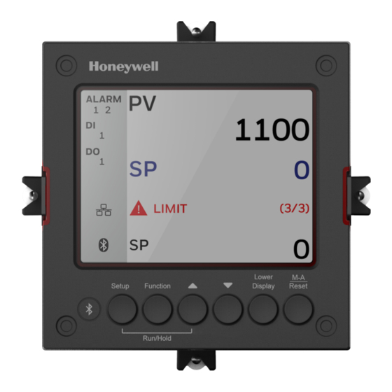
Chapter 2 - Introduction Operator Interface Function of Displays Figure 2-1: Function of Displays Table 2-1: Function of Displays Item Description Upper display shows Process Variable value (maximum 10 digits including decimal point, eg. -XXXX.X). Its unit can be F, C or none. Middle display shows working Setpoint and its value (maximum 10 digits including decimal point, eg. - Page 21 Chapter 2 - Introduction Item Description percent of bar chart. Diagnostics display shows diagnostic messages. See Diagnostic Messages for more information. Lower display shows key-selected operating parameters such as Output, Setpoints, Inputs, Deviation, active Tuning Parameter Set, Timer status, or minutes remaining in a setpoint ramp.
-
Page 22: Function Of Keys
Chapter 2 - Introduction Function of Keys Figure 2-2: Function of Keys Table 2-2: Function of Keys Item Description NEMA4X and IP66 screw attachment (each corner). Bluetooth transmitter Enables to configure and operate controllers from mobility devices (mobile phones and tablet PCs), and download/upload the complete device configuration. - Page 23 Chapter 2 - Introduction Item Description up groups. Function key Selects functions within each configuration group. When in the main screen, press it to select next setpoint source from LP1, LP2, LP3, LP4 and RSP. When in the setup screen. The first press will set the focus to the Function Group, and the subsequent presses used to navigate between Function Group and Option Group.
-
Page 24: Pc Software And Mobile Device App
PC Software and Mobile Device App The controller can be configured via a Honeywell EasySet or PC software. Honeywell EasySet is running on a Mobile Device, and PC software is running on a Desktop or a laptop computer. -
Page 25: Configuration Tool Via Bluetooth
3 meters. This app can be installed on IOS 12.0 or higher operating system. See Configuration via Honeywell EasySet for more information. Figure 2-3: Screen capture of Honeywell EasySet running on a Mobile Device Features Create configurations with the application (Honeywell EasySet) running on a Mobile Device. -
Page 26: Ce Conformity (Europe)
Chapter 2 - Introduction Bluetooth communications The Bluetooth connection provides a non-intrusive wireless connection with the instrument and maintains NEMA4X and IP66 integrity. No need to get access to the back of the controller to communicate with the instrument, no need to take your screwdriver to wire the communication cable, no wiring mistake possible. - Page 27 Chapter 2 - Introduction : Category II (EN61010-1) Installation Category (Overvoltage Category) Energy-consuming equipment supplied from the fixed Installation. Local level appliances, and Industrial Control Equipment : Pollution Degree 2. Normally non-conductive Pollution Degree pollution with occasional conductivity caused by condensation. (Ref. IEC 664-1) : Group 1, Class A, ISM Equipment (EN61326-1, EMC Classification...
-
Page 28: North America
Chapter 2 - Introduction North America Installation Category (Overvoltage Category): Category II (EN61010-1) Pollution Degree: Pollution Degree 2: Normally non-conductive pollution with occasional conductivity caused by condensation. (Ref. IEC 664-1) WARNING: If this equipment is used in a manner not specified by the manufacturer, the protection provided by the equipment may be impaired. - Page 29 Chapter 2 - Introduction harmful interference to radio communications. However, there is no guarantee that interference will not occur in a particular installation. If this equipment does cause harmful interference to radio or television reception, which can be determined by turning the equipment off and on, the user is encouraged to try to correct the interference by one or more of the following measures: Reorient or relocate the receiving antenna.
- Page 30 CHAPTER INSTALLATION What's in this section? The following topics are covered in this section. In this section: Overview Condensed Specifications Model Number Interpretation Control and Alarm Relay Contact Information Mounting Wiring Wiring Diagrams...
-
Page 31: Chapter 3 - Installation
Chapter 3 - Installation Overview Introduction UDC2800 installation consists of mounting and wiring the controller according to the instructions given in this section. Read the pre- installation information, check the model number interpretation, and become familiar with your model selections, then proceed with installation. - Page 32 Chapter 3 - Installation Specifications : ± 0.01% of Full Scale span / ˚C change- Temperature Stability typical Input Impedance 0-20 / 4-20 Milliampere Input: 250 ohms All Others: 10 megohms Maximum Lead Wire Resistance Thermocouples: 50 ohms/leg 100 ohm, 200 ohm and 500 ohm RTD: 100 ohms/leg 100 ohm Low RTD: 10 ohms/leg Slidewire Inputs for Position Proportional Control 100 ohms minimum to 1000 ohms maximum...
- Page 33 Chapter 3 - Installation Specifications analog inputs and all outputs except for the Second Current Output. On contact closure the controller will respond according to how each digital input is configured. Opening the contact causes a return to previous state. The second Digital Input is mutually exclusive with the Second Current Output.
- Page 34 Chapter 3 - Installation Specifications damage the instrument. Maximum Source Current: 20 mA Overload Protection: 25 mA Current Outputs (One or Two) These outputs provide a 21 mA dc maximum into a negative or positive grounded load or into a non-grounded load. Current outputs are isolated from each other, line power, earth ground and all inputs.
- Page 35 Chapter 3 - Installation Specifications RS485 Modbus : 4800, 9600,19,200 or 38,400 baud selectable Baud Rate : Floating point or integer Data Format Communications Interface Length of Link (Optional) 2000 ft (600 m) max. with Belden 9271 Twinax Cable and 120 ohm termination resistors 4000 ft.
- Page 36 Chapter 3 - Installation Specifications Two relays or open collector outputs. Control action can be set for direct or reverse. Time Proportional Relay Resolution: 3 msec : A single 4-20 mA current output signal that Current Proportional can be configured for direct or reverse action. : This can be a single current output Current Proportional Duplex can provide both heat and cool signals (4-12 mA cool, 12-20 mA...
- Page 37 Chapter 3 - Installation Specifications Operation Automatic with Local Setpoint Automatic with Remote Setpoint Dimensions See Overall Dimensions for more information. Mounting Panel-mounted, 4.5-inch (114 mm) depth Wiring Screw terminals on the rear of the case. Connections See Wiring Diagrams for more information. Power 16 VA maximum (100 to 240 Vac) Consumption...
- Page 38 Chapter 3 - Installation Specifications kV, Common Mode and Differential Mode. The instrument is capable of meeting these test levels with no component failures, no reset, and no incorrect outputs. Radio Frequency Immunity: No effect on performance from a 5 W walkie-talkie Interference (RFI) operated at 151 or 450 MHz, one meter from the controller.
-
Page 39: Model Number Interpretation
This information will also be useful when you wire your controller. UDC2800 Universal Digital Controller Model Selection Guide The UDC2800 controller packs new powerful features while retaining all the simplicity and flexibility of the industry standard UDC2500 controller including: Enhanced Display... - Page 40 Chapter 3 - Installation Key Number _ _ _ _ _ _ _ _ _ _ _ _ _ _ _ Key Number - UDC2800 Single Loop Controller Description Selection Availability Digital Controller for use with 100 to 240 Vac Power DC2800 ↓...
- Page 41 Chapter 3 - Installation Table III - Input 1 and Input 2 Input 1 TC, RTD, mV, 0-5V, 1-5V, 0-10V 1 _ _ • • (See Note 1 TC, RTD, mV, 0-5V, 1-5V, 0-10V, 0-20mA, 4- 2 _ _ • •...
- Page 42 Not Available With Restriction Letters Table Selection Table Selection EE, R_ 1 _ _ UDC2800 Universal Digital Controller Supplemental Accessories & Kits Description Part Number Front panel assembly, UDC 2800/2900 50159507-501 TFT-LCD module for UDC2800, CTM320240N01 50152823-501 Power/Output PWA without E-M Relays (90-264 Vac Operation)
- Page 43 Mounting Kits (12 Brackets) 51452763-501 DIN Adaptor Kit 30755223-003 Panel Bracket Kit 50004821-501 Quick Start Guide English 51-52-25-158 Product Manual English 51-52-25-157 ATTENTION: It is recommended to use Honeywell provided accessories and kits. Otherwise, using non-Honeywell provided components would take risks.
-
Page 44: Control And Alarm Relay Contact Information
Chapter 3 - Installation Control and Alarm Relay Contact Information Control Relays ATTENTION: Control relays operate in the standard control mode (that is, energized when output state is on). Table 3-2: Control Relay Contact Information Unit Control Relay Control Relay Output #1 or #2 Indicator Power Wiring... -
Page 45: Mounting
Chapter 3 - Installation Table 3-3: Alarm Relay Contact Information Variable NOT in Alarm Variable in Alarm State State Unit Alarm relay power Wiring Relay Relay Indicators Indicators Contact COntact N.O. Open Open N.C. Closed Closed N.O. Closed Open N.C. Open Closed Mounting... -
Page 46: Overall Dimensions
Chapter 3 - Installation Overall Dimensions Dimensions and Mounting Figure 3-1: Mounting Dimensions (not to scale) -
Page 47: Mounting Method
Chapter 3 - Installation Mounting Method Before mounting the controller, refer to the nameplate on the outside of the case and make a note of the model number. It will help later when selecting the proper wiring configuration. Figure 3-2: Mounting Methods Item Description Attach screws and washers here for water protection... -
Page 48: Mounting Procedure
Chapter 3 - Installation Mounting Procedure Table 3-4: Mounting Procedure Step Action Mark and cut out the controller hole in the panel according to the dimension information. See Overall Dimensions for more information. Orient the case properly and slide it through the panel hole from the front. Remove the mounting kit from the shipping container and install the kit as follows: For normal (NEMA3/IP55) installation two mounting clips are required. ... -
Page 49: Wiring
Chapter 3 - Installation Wiring Electrical Considerations Line voltage wiring This controller is considered “rack and panel mounted equipment” per EN61010-1, Safety Requirements for Electrical Equipment for Measurement, Control, and Laboratory Use, Part 1: General Requirements. Conformity with 2014/35/EU, the Low Voltage Directive requires the user to provide adequate protection against a shock hazard. - Page 50 Chapter 3 - Installation Controller Grounding PROTECTIVE BONDING (grounding) of this controller and the enclosure in which it is installed shall be in accordance with National and Local electrical codes. To minimize electrical noise and transients that may adversely affect the system, supplementary bonding of the controller enclosure to a local ground, using a 14AWG ~ 20AWG copper conductor, is recommended.
-
Page 51: Wiring Diagrams
Chapter 3 - Installation Permissible Wiring Bundling Table 3-5: Permissible Wiring Bundling Bundle No. Wire Functions Line power wiring Earth ground wiring Line voltage control relay output wiring Line voltage alarm wiring Analog signal wire, such as: Input signal wire (thermocouple, 4 to 20 mA, etc.) 4-20 mA output signal wiring. - Page 52 Chapter 3 - Installation Time Duplex with no alarm relay(s); Three Position Step Control with no alarm relays. These selections may all be made via the keyboard and by wiring to the appropriate output terminals; there are no internal jumpers or switches to change. ...
- Page 53 Chapter 3 - Installation Function of Other Outputs Output Algorithm Output 1/2 Function of Auxiliary Type Option Output 1/2 Output #3 Output #4 Output 100% Relay and 2 Current Outputs 1 Alarm 2 Alarm 1 Not Needed Current = COOL Output and 2 and HEAT...
-
Page 54: Wiring The Controller
Chapter 3 - Installation Function of Other Outputs Output Algorithm Output 1/2 Function of Auxiliary Type Option Output 1/2 Output #3 Output #4 Output Output 1/2 option. INU = Installed, Not Used – The installed Output 1/2 option is not used for the configured output algorithm type. - Page 55 Item Description AC/DC Line Voltage Terminals. Output 3 Terminals (Output #2 or Alarm #2 in the Table I of UDC2800 Universal Digital Controller Model Selection Guide). ATTENTION: If they are used as Relay Outputs, the wire gauge should be AWG 14~22.
- Page 56 Chapter 3 - Installation Figure 3-4: Mains Power Supply Item Description PROTECTIVE BONDING (grounding) of this controller and the enclosure in which it is installed, shall be in accordance with National and local electrical codes. To minimize electrical noise and transients that may adversely affect the system, supplementary bonding of the controller enclosure to local ground using a 14AWG ~ 20AWG copper conductor is recommended.
- Page 57 Chapter 3 - Installation Figure 3-5: Input 1 Connections Item Description The 250 ohm resistor for milliamp inputs is supplied with the controller when those inputs are specified. These items must be installed prior to start up when the controller is wired. For 0-20 mA applications, the resistor should be located at the transmitter terminals if Burnout detection is desired.
- Page 58 Chapter 3 - Installation Figure 3-6: Input 2 Connections Item Description The 250 ohm resistor for milliamp inputs is supplied with the controller when those inputs are specified. These items must be installed prior to start up when the controller is wired. For 0-20 mA applications, the resistor should be located at the transmitter terminals if Burnout detection is desired.
- Page 59 Chapter 3 - Installation Item Description Input 2 is used to measure the Slidewire Input for Position Proportional Control. Figure 3-7: Electromechanical Relay Output Item Description Alarm #2 is not available with Time Proportional Duplex or Three Position Step Control unless the Dual Relay Option is used. Electromechanical relays are rated at 5 Amps @ 125 Vac or 250 Vac or 30 Vdc.
- Page 60 Chapter 3 - Installation Figure 3-8: Open Collector Output Item Description CAUTION: Open collector outputs are internally powered at 28 Vdc (0 mA) ~ 24 Vdc (20 mA). Connecting and external power supply will damage the controller. Alarm #2 is not available with Time Proportional Duplex or Three Position Step Control unless the Dual Relay option is used.
- Page 61 Chapter 3 - Installation Figure 3-9: Dual Electromechanical Relay Option Output Item Description Dual Electromechanical relays are rated at 2 Amps @125 Vac or 250 Vac or 30 Vdc. Customer should size fuses accordingly. Use Fast Blow fuses only. Electromechanical relays are rated at 5 Amps @ 125 Vac or 250 Vac or 30 Vdc. Users should size fuses accordingly.
- Page 62 Chapter 3 - Installation See the table Universal Output Functionality and Restrictions relay terminal connections for other Output Algorithm Types. Figure 3-11: Position Proportional or Three Position Step Control Connections, model DC2800-EE or DC2900-EE Item Description Alarm #2 is not available with this configuration. DC2800-EE or DC2900-EE Electromechanical Relays are rated at 5 Amps at 120 Vac or 240 Vac or 24 Vdc.
- Page 63 Chapter 3 - Installation Item Description Users should size fuses accordingly. Use Fast Blow fuses only. See Input 2 Wiring Diagram for Slidewire Connections. Figure 3-13: RS485 Communications Option Connections Item Description Do not run the communications lines in the same conduit as AC power. Use shielded twisted pair cables (Belden 9271 Twinax or equivalent).
- Page 64 Chapter 3 - Installation Figure 3-14: Ethernet Communications Option Connections Item Description Do not run the communications lines in the same conduit as AC power. Correct connections may require the use of an Ethernet cross-over cable. Use shielded twisted pair, Category 5e (STP CAT5e) Ethernet cable. For Ethernet cable with RJ45 connector, an Ethernet Adapter Kit is required to install on the terminals.
- Page 65 Chapter 3 - Installation Figure 3-16: Transmitter Power for 4-20 mA — 2 wire Transmitter Using Open Collector Alarm 2 A2S1TY Deviation Output Figure 3-17: Transmitter Power for 4-20 mA — 2 Wire Transmitter Using Auxiliary Output...
-
Page 66: Chapter 4 - Configuration
CHAPTER CONFIGURATION In this section: Overview Configuration Prompt Hierarchy Configuration Procedure Security Set Up Group Tuning Set Up Group SP Ramp/Program Set Up Group SP PROG2 ~ PROG 8 Set Up Group Accutune Set Up Group Algorithm Set Up Group Output Set Up Group Input 1 Set Up Group Input 2 Set Up Group... -
Page 67: Overview
Chapter 4 - Configuration Overview Configuration is a dedicated operation where you use straightforward keystroke sequences to select and establish (configure) pertinent control data best suited for your application. To assist you in the configuration process, there are prompts that appear in the upper, middle and lower displays. - Page 68 Chapter 4 - Configuration Setup Group Function Prompts Ramp/Program SP Program 2~8 Accutune Algorithms...
- Page 69 Chapter 4 - Configuration Setup Group Function Prompts Output Input 1 Input 2 Control Options...
- Page 70 Chapter 4 - Configuration Setup Group Function Prompts Communication Alarms Display Input1 Calib (Calibration) Input2 Calib (Calibration) Slidewire Calib (Calibration) Current Calib (Calibration)
-
Page 71: Configuration Procedure
Chapter 4 - Configuration Setup Group Function Prompts Auxiliary Calib (Calibration) Status Configuration Procedure Introduction Each of the Set Up groups and their functions are pre-configured at the factory. The factory settings are shown in Table Security Group Function Prompts through Table Display Group Function Prompts. - Page 72 Chapter 4 - Configuration Step Operation Press Result Select a Function Function key Enter in the first function prompt of Parameter the selected set up group. Increment key or Press Increment key or Decrement Decrement key keys to display the other function prompts of the selected set up group.
-
Page 73: Security Set Up Group
Chapter 4 - Configuration Security Set Up Group Introduction Security enables you to configure lockout, password, restore the product, and we recommend that you configure this group last, after all other configuration data has been loaded. ATTENTION: Users must be careful while entering the password as the password is not hidden. - Page 74 Lockout applies to one of the functional groups: Configuration, Calibration, Tuning, Accutune. ATTENTION: Do not configure it until all configuration is complete. NOTE: In the Honeywell EasySet app, lockout options appears under the security group only after entering the password. None No lockout;...
- Page 75 Chapter 4 - Configuration Selections or Function Range of Parameter Definition Prompt Setting Run/Hold Allows you to disable the Run/Hold key, for either SP Ramp or SP Program. The Run/Hold key is never disabled when used to acknowledge a latched alarm Disable Disable the Run/Hold Key Enable...
-
Page 76: Tuning Set Up Group
Chapter 4 - Configuration Selections or Function Range of Parameter Definition Prompt Setting and is not available via communications. ATTENTION: Can only be viewed when the password you entered is correct. Tuning Set Up Group Introduction Tuning consists of establishing the appropriate values for the tuning constants you are using so that your controller responds correctly to changes in process variable and setpoint. - Page 77 Chapter 4 - Configuration Selections or Function Range of Parameter Definition Prompt Setting of the measured variable for which a proportional controller will produce a 100 % change in its output. is the ratio of output change (%) over the Gain 1 measured variable change (%) that caused it.
- Page 78 Chapter 4 - Configuration Selections or Function Range of Parameter Definition Prompt Setting NOTE: The selection of whether Minutes per is used is made in Repeat Repeats per Minute set up group under the prompt Control Reset Unit Manual Reset –100 to It is only applicable if you use control algorithm PD with +100 (in %...
- Page 79 Chapter 4 - Configuration Selections or Function Range of Parameter Definition Prompt Setting Mins/Rpt 2 50.00 Duplex models for the "COOL" zone of Heat/Cool applications or for the second set of PID constants. Reset Rpts/Min 2 Proportional 0.1 to 9999 , and Proportional Band 3 Gain 3...
- Page 80 Chapter 4 - Configuration Selections or Function Range of Parameter Definition Prompt Setting of the set up group is Control Algorithm Algorithms configured as PID A PID B PD+Manual Reset Three Position Step of the set up group is configured as PID Sets Control 4 Sets Keyboard...
-
Page 81: Sp Ramp/Program Set Up Group
Chapter 4 - Configuration SP Ramp/Program Set Up Group Introduction Set Point Ramp, Set Point Rates and Set Point Programs can be configured in this group. A single Setpoint Ramp ( ) can be configured to occur SP Ramp between the current local setpoint and a final local setpoint over a time interval of from 1 to 255 minutes. - Page 82 Chapter 4 - Configuration The current setpoint reaches the final setpoint. The ramp timer is timeout, i.e., the ramp time is expired. when a ramp completes, despite whatever value the current setpoint was at that moment, it will be set to the final setpoint immediately. is a configurable feature and means that, at initialization, PV Hot Start the setpoint is set to the current PV value and the Ramp or Program...
- Page 83 Chapter 4 - Configuration Function Prompts Table 4-5: SP Ramp/Program Group Function Prompts Function Selections or Range Parameter Definition Prompt of Setting SP Ramp —Make a selection to Single Setpoint Ramp Function enable or disable the setpoint ramp function. Make sure you configure a ramp time and a final setpoint value.
- Page 84 Chapter 4 - Configuration Function Selections or Range Parameter Definition Prompt of Setting cause the SP portion of Accutune to abort. PV Tune will continue to function normally. Ramp is placed into HOLD while tuning (TUNE configuration). SP Rate —Lets you configure a specific Setpoint Rate Function rate of change for any local setpoint change.
- Page 85 Chapter 4 - Configuration Function Selections or Range Parameter Definition Prompt of Setting ATTENTION: SP Ramp must be disabled for SP Program prompts to appear. If SP Rate is enabled, it does not operate while an SP Program is running Disable Disables setpoint programming.
- Page 86 Chapter 4 - Configuration Function Selections or Range Parameter Definition Prompt of Setting Disable Disable the function. To Begin It allows the setpoint program to be reset to the beginning of the first segment in the first program. Rerun It allows the setpoint program to rerun from the first segment in the current program.
- Page 87 Chapter 4 - Configuration Selections or Function Prompt Range of Parameter Definition Setting Ramp Unit Engineering Units for Ramp Segments Time Hrs:Mins Time in hours: minutes Rate EU/Min Rate in Engineering units per minute 0~999 EU/Min Rate EU/Hr Rate in Engineering units per hour 0~999 EU/Hr Recycles 0 to 99 recycles...
-
Page 88: Sp Prog2 ~ Prog 8 Set Up Group
Chapter 4 - Configuration Selections or Function Prompt Range of Parameter Definition Setting (0-99 hours:0- 59 minutes Segment 3 Ramp Selections are Same as above same as above. Segment 4 SP & Segment 4 Time Segment 5 Ramp Segment 6 SP & Segment 6 Time Segment 7 Ramp Segment 8 SP &... - Page 89 Chapter 4 - Configuration Selections or Range of Function Prompt Parameter Definition Setting End Segment 2 to 8 even numbers Always End Segment Number end in a soak segment (2, 4, 6 and 8) Ramp Unit Engineering Units for Ramp Segments Time Hrs:Mins Time in hours: minutes...
- Page 90 Chapter 4 - Configuration Selections or Range of Function Prompt Parameter Definition Setting Segment 6 SP & Segment 6 Time Segment 7 Ramp Segment 8 SP & Segment 8 Time...
-
Page 91: Accutune Set Up Group
Chapter 4 - Configuration Accutune Set Up Group Introduction Accutune III automatically calculates GAIN, RATE, and RESET TIME (PID) tuning constants for your control loop. When initiated on demand, the Accutune algorithm measures a process step response and automatically generates the PID tuning constants needed for no overshoot on your process. - Page 92 Chapter 4 - Configuration Function Prompts Table 4-7: Accutune Group Function Prompts Function Selections or Parameter Definition Prompt Range of Setting Fuzzy —Can be enabled or Fuzzy Overshoot Suppression Suppression disabled independently of whether Demand Tuning or SP Tuning is enabled or disabled. Disable Disables Fuzzy Overshoot Suppression.
- Page 93 Chapter 4 - Configuration Function Selections or Parameter Definition Prompt Range of Setting Disable The current SetPoint is used to derive a single set of blended tuning parameters. This tuning is performed over the range of the output limits similar to Simplex Tuning. The Tuning Parameters derived are placed into both the HEAT and COOL tune sets (PID 1 and PID 2).
-
Page 94: Algorithm Set Up Group
Chapter 4 - Configuration Algorithm Set Up Group Introduction This data deals with various algorithms in the controller and Timer functions. The Timer section allows you to configure a time-out period and to select the timer start by either the keyboard ( RUN/HOLD key) or Alarm 2. - Page 95 Chapter 4 - Configuration Selections or Range of Function Prompt Parameter Definition Setting setpoint (SP) to determine the sign of the error (ERROR = PV–SP). The ON/OFF algorithm operates on the sign of the error signal. In Direct Acting Control, when the error signal is positive, the output is 100 %;...
- Page 96 Chapter 4 - Configuration Selections or Range of Function Prompt Parameter Definition Setting Derivative (D)—to the error signal. ATTENTION: PID A should not be used for Proportional only action; i.e., no integral (reset) action. Instead, use PD+ Manual Reset with rate set to —Regulates the Proportional (Gain) controller’s output in proportion to...
- Page 97 Chapter 4 - Configuration Selections or Range of Function Prompt Parameter Definition Setting equation is computed with no integral contribution. The MANUAL RESET, which is operator adjustable, is then added to the present output to form the controller output. Switching between manual and automatic mode will be bumpless.
-
Page 98: Output Set Up Group
Chapter 4 - Configuration Selections or Range of Function Prompt Parameter Definition Setting only an approximation, it is “corrected” each time the controller drives the motor to one of its stops (0 % or 100 %). It avoids all the control problems associated with the feedback slidewire (wear, dirt, noise). - Page 99 Chapter 4 - Configuration Selections or Range of Function Prompt Parameter Definition Setting Enable timer option. The timer option allows you to configure a timeout period and to select timer start by either the keyboard (RUN/HOLD key) or Alarm 2. A digital input can also be configured to start the timer.
- Page 100 Chapter 4 - Configuration Selections or Range of Function Prompt Parameter Definition Setting Alarm 1 timer with the keyboard (Run/Hold key) or Alarm 1. Increment Minutes allows you to increment Increment the timer in either minutes or Seconds seconds. Input Math Algorithms —Controllers with two inputs are provided with one input algorithm.
- Page 101 Chapter 4 - Configuration Selections or Range of Function Prompt Parameter Definition Setting Three Position Step Control applications. The following formula applies: Controller Output = PID Output + (Input A x Ratio A + Bias A ) x (100 / Input A Range) Feedforward Mult Feedforward Multiplier —...
- Page 102 Chapter 4 - Configuration Selections or Range of Function Prompt Parameter Definition Setting...
- Page 103 Chapter 4 - Configuration Selections or Range of Function Prompt Parameter Definition Setting Low Select Input Low Select with Ratio and Bias — This selection specifies the (See Note 2) PV or SP as the lower of Input 1 or Input 2.
- Page 104 Chapter 4 - Configuration Selections or Range of Function Prompt Parameter Definition Setting Hi – Calc Lo) + Alg1Bias...
- Page 105 Chapter 4 - Configuration Selections or Range of Function Prompt Parameter Definition Setting Carbon A Carbon Potential A —Make this selection if you have a Cambridge or Marathon monitor type Zirconium Oxide sensor. See Note 3. Carbon B Carbon Potential B —Make this selection if you have a Corning type Zirconium Oxide sensor.
- Page 106 Chapter 4 - Configuration Selections or Range of Function Prompt Parameter Definition Setting range within the region of 1000 °F to 2200 °F and a minimum carbon probe value of 800 millivolts. Oxygen Percent Oxygen Range —Make this selection if you are using a Zirconium Oxide Oxygen Probe to measure Percent of Oxygen in a range of 0 to 40 % O₂...
- Page 107 Chapter 4 - Configuration Selections or Range of Function Prompt Parameter Definition Setting functions was selected as the Input Algorithm. See Note 2. Calculated Low –999. To 9999. Calculated Variable Low Scaling Floating Factor for Input Algorithm 1 —Used (in engineering units) only when either Summer, Input Hi/Lo, or one of the General Math functions was selected as the Input...
- Page 108 Chapter 4 - Configuration Selections or Range of Function Prompt Parameter Definition Setting Percent CO 0.020 to 0.350 Percent Carbon is only applicable (fractional percent of when Carbon Potential is selected. Enter the value in percent carbon monoxide that is applicable for the enriching gas used in fractional form.
-
Page 109: Output Set Up Group
Chapter 4 - Configuration Output Set Up Group Introduction This group deals with various output types in the controller, the Digital Output Status and the Current Output operation. ATTENTION: The Tuning Group is automatically configured to have two PID sets when a Duplex Control Algorithm is selected. Function Prompts Table 4-9: OUTPUT Group Function Prompts Function... - Page 110 Chapter 4 - Configuration Function Selections or Range Parameter Definition Prompt of Setting Current Simplex Type of output using one 4 mA to 20 mA signal that can be fed into a positive or negative grounded load of 0 to 1000 ohms. This signal can easily be configured for 4-20 mA or 0-20 mA operation via the CO Range configuration, below.
- Page 111 Chapter 4 - Configuration Function Selections or Range Parameter Definition Prompt of Setting current controls cool. ATTENTION: Other prompts affected: Out Range Time Current Time Current Duplex is similar to Current Time except that current is active for 50 % to 100 % and time is active for 0 % to 50 %.
- Page 112 Chapter 4 - Configuration Function Selections or Range Parameter Definition Prompt of Setting 49.0 and the HIGH VAL selection to 0.0. 100 Percent Current Duplex Range (FULL) enables the Current Output to provide both heat and cool functions for control over 0-100 % of the controller output.
- Page 113 Chapter 4 - Configuration Function Selections or Range Parameter Definition Prompt of Setting algorithms, it may be used to perform an Auxiliary Output function. Disable Disable Input 1 Input 1 Input 2 Input 2 Process Variable Deviation Deviation Output Output Setpoint Local SP 1 Local Setpoint 1...
- Page 114 Chapter 4 - Configuration Function Selections or Range Parameter Definition Prompt of Setting However, keep in mind that relay output types can only be scaled 0 % to 100 %. CO Range 4-20mA Current Output Range allows the user to easily select 4-20 mA output or 0-20 mA output 0-20mA operation without the need for recalibration of...
-
Page 115: Input 1 Set Up Group
Chapter 4 - Configuration Input 1 Set Up Group Introduction This data deals with various parameters required to configure Input Function Prompts Table 4-10: INPUT 1 Group Function Prompts Function Selections or Parameter Definition Prompt Range of Setting Input 1 Type –... - Page 116 Chapter 4 - Configuration Function Selections or Parameter Definition Prompt Range of Setting TC N High N Thermocouple High (Nicrosil-Nisil) TC N Low N Thermocouple Low (Nicrosil-Nisil) TC R R Thermocouple TC S S Thermocouple TC T High T Thermocouple High TC T Low T Thermocouple Low TC C High...
- Page 117 Chapter 4 - Configuration Function Selections or Parameter Definition Prompt Range of Setting Oxygen Oxygen Probe Input Input 1 TC B —This selection lets Transmitter Characterization Transmitter you instruct the controller to characterize a TC E High linear input to represent a non-linear one. If characterization is performed by the transmitter TC E Low itself, then select Linear.
- Page 118 Chapter 4 - Configuration Function Selections or Parameter Definition Prompt Range of Setting Linear Square Root Input 1 High –999. To 9999. Input 1 High Range Value in engineering units is Value Floating (in displayed for all inputs but can only be engineering configured for linear or square root transmitter units)
- Page 119 Chapter 4 - Configuration Function Selections or Parameter Definition Prompt Range of Setting Input 1 Filter 0 to 120 Filter for Input 1 —A software digital filter is seconds No provided for Input 1 to smooth the input signal. filter = 0 You can configure the first order lag time constant from 1 to 120 seconds.
- Page 120 Chapter 4 - Configuration Function Selections or Parameter Definition Prompt Range of Setting ATTENTION: For Burnout to function properly on a 0-20 mA input type (or a 0- 5V type that uses a dropping resistor), the dropping resistor must be remotely located (across the transmitter terminals). ...
-
Page 121: Input 2 Set Up Group
Chapter 4 - Configuration Input 2 Set Up Group Introduction This data deals with various parameters required to configure Input Function Prompts Table 4-11: Input 2 Group Function Prompts Selections or Function Range of Parameter Definition Prompt Setting Input 2 Type –... - Page 122 Chapter 4 - Configuration Selections or Function Range of Parameter Definition Prompt Setting TC M High M Thermocouple High (Ni-Ni-Moly) TC M Low M Thermocouple Low (Ni-Ni-Moly) TC N High N Thermocouple High (Nicrosil-Nisil) TC N Low N Thermocouple Low (Nicrosil-Nisil) TC R R Thermocouple TC S...
- Page 123 Chapter 4 - Configuration Selections or Function Range of Parameter Definition Prompt Setting Input 2 Type TC Differential Thermocouple Differential Slidewire 100-1K ohm Slidewire (For Position Proportional Applications) Input 2 TC B —This selection lets you Transmitter Characterization Transmitter instruct the controller to characterize a linear input TC E High to represent a non-linear one.
- Page 124 Chapter 4 - Configuration Selections or Function Range of Parameter Definition Prompt Setting RTD Pt100 RTD Pt200 RTD Pt500 Linear Square Root Input 2 High –999. To in engineering units is Input 2 High Range Value Value 9999. displayed for all inputs but can only be configured Floating (in for linear or square root transmitter engineering...
- Page 125 Chapter 4 - Configuration Selections or Function Range of Parameter Definition Prompt Setting No Burnout If Input 2 is being used in the Control Algorithm (such as the PV or RSP input parameter), then the pre-configured Failsafe output (selected in the Control set up group) is applied when a failed input is detected (does not apply for an input out of range).
-
Page 126: Control Set Up Group
Chapter 4 - Configuration Selections or Function Range of Parameter Definition Prompt Setting ATTENTION: The Thermocouple Health feature is disabled when NO FS is configured. Control Set Up Group Introduction The functions listed in this group deal with how the controller will control the process including: Number of Tuning Parameter Sets, Setpoint Source, Tracking, Power-up Recall, Setpoint Limits, Output Direction and Limits, Deadband, and Hysteresis. - Page 127 Chapter 4 - Configuration Function Selections or Range Parameter Definition Prompt of Setting 1 Set - Only one set of tuning One Set Only parameters is available. Configure the values for: Gain 1 or Proportional Band 1, Rate 1 Min, Reset Mins/Rpt 1 or Reset Rpts/Min 1 2 Sets Keyboard - Two sets of...
- Page 128 Chapter 4 - Configuration Function Selections or Range Parameter Definition Prompt of Setting Switchover Value, the controller will use Gain 1 or Proportional Band 1, Rate 1 Min, and Reset Mins/Rpt 1 or Reset Rpts/Min 1. When the setpoint is than the value GREATER set at prompt Switchover Value, the controller...
- Page 129 Chapter 4 - Configuration Function Selections or Range Parameter Definition Prompt of Setting the value set at prompt Switchover Value, the controller will use Gain 2 or Proportional Band 2, Rate 2 Min, and Reset Mins/Rpt 2 or Reset Rpts/Min 2. The active PID SET can be read in the lower display.
- Page 130 Chapter 4 - Configuration Function Selections or Range Parameter Definition Prompt of Setting ATTENTION: Only appears when PID Sets is configured for 2 Sets PV Switchover, 2 Sets SP Switchover, 4 Sets PV Switchover, or 4 Sets SP Switchover. Switchover Value in - This is the value of Automatic Switchover Value...
- Page 131 Chapter 4 - Configuration Function Selections or Range Parameter Definition Prompt of Setting Remote SP —This selection Remote Setpoint Source Source determines what your remote setpoint source will be when toggled by the SP Select key or Digital Input. NONE No remote setpoint.
- Page 132 Chapter 4 - Configuration Function Selections or Range Parameter Definition Prompt of Setting configured, the LSP will not be altered when transfer from RSP to LSP is made. Local setpoint tracks the PV when in manual. Remote SP Local setpoint tracks remote setpoint when in automatic.
- Page 133 Chapter 4 - Configuration Function Selections or Range Parameter Definition Prompt of Setting —This selection determines what position Mode the motor will be in when powered up or in the failsafe position. Last —At power-up in automatic mode, Last Output the motor position will be the last one prior to power down.
- Page 134 Chapter 4 - Configuration Function Selections or Range Parameter Definition Prompt of Setting Enable Allows output rate. Disable Disables output rate. Rate Up % 0 to 9999 % per - This selection limits the Output Rate Up Value minute rate at which the output can change upward. Enter a value in percent per minute.
- Page 135 Chapter 4 - Configuration Function Selections or Range Parameter Definition Prompt of Setting Deadband is an adjustable gap between the Deadband operating ranges of output 1 and output 2 in which neither output operates (positive value) or both outputs operate (negative value). –5.0 to 25.0 % Time Duplex, Current Duplex, Current Time or Time Current...
- Page 136 Chapter 4 - Configuration Function Selections or Range Parameter Definition Prompt of Setting Value slidewire fails. ATTENTION: must TPSC Power Up Mode be configured for Failsafe 0 Percent Motor goes to closed position. 100 Percent Motor goes to open position. Preset 0 to 100 % - At power-up,...
- Page 137 Chapter 4 - Configuration Function Selections or Range Parameter Definition Prompt of Setting limit range. For example, if SP = 1500 and the SP HiLIM is changed to 1200, the new local setpoint will be 1200. If PV source is one of the Analog Inputs, then the SP High Limit and SP Low Limit values must be between the Input High and Input Low values for the input type configured.
-
Page 138: Options Set Up Group
Chapter 4 - Configuration Options Set Up Group Introduction The Options group lets you configure the remote mode switch (Digital Inputs) to a specific contact closure response, or configure the Auxiliary Output to be a specific selection with desired scaling. Function Prompts Table 4-13: Options Group Function Prompts Selections or Range... - Page 139 Chapter 4 - Configuration Selections or Range Function Prompt Parameter Definition of Setting It represents the value of the Process Variable. PV = Input XxRatioX + BiasX Deviation Deviation (Process Variable Minus Setpoint) represents –100 % to +100 % of the selected PV span in engineering units.
- Page 140 Chapter 4 - Configuration Selections or Range Function Prompt Parameter Definition of Setting Setpoint represents the value of the setpoint currently in use (LSP1, LSP2, LSP3, LSP4, RSP or CSP) and is shown in the same units as those used by the PV. Local SP 1 Auxiliary output represents Local Setpoint 1 regardless of active...
- Page 141 Chapter 4 - Configuration Selections or Range Function Prompt Parameter Definition of Setting within the range of — This is a value in engineering units the selected variable used to represent all Auxiliary to represent the Output parameters except Output. minimum output (0 For Output, this is a value in percent or 4 mA)
- Page 142 Chapter 4 - Configuration Selections or Range Function Prompt Parameter Definition of Setting To Local SP 2 Contact closure puts the controller into local setpoint 2. To Local SP 3 Contact closure puts the controller into local setpoint 3. To Local SP 4 Contact closure puts the controller into local setpoint 4.
- Page 143 Chapter 4 - Configuration Selections or Range Function Prompt Parameter Definition of Setting To Begin External SP Program Reset —Contact closure resets SP Program back to the beginning of the first segment in the program and places the program in the HOLD mode. Program cycle number is not affected.
- Page 144 Chapter 4 - Configuration Selections or Range Function Prompt Parameter Definition of Setting To Preset Auto Automatic Output —Contact closure Output sends output to the value set at Control prompt AUTO OUT when the controller is in the Automatic mode. Reopening the contact returns the controller to the normal output.
- Page 145 Chapter 4 - Configuration Selections or Range Function Prompt Parameter Definition of Setting value and normal PID action will then take over control. The transfer is bumpless. To Remote SP Contact closure selects the Remote setpoint. ATTENTION: When DI1 or DI2 selects "To Remote SP,"...
- Page 146 Chapter 4 - Configuration Selections or Range Function Prompt Parameter Definition of Setting loop to Manual mode. Opening the switch has no effect. If the MAN/AUTO key is pressed while the switch is closed, the loop will return to Automatic mode. PV Hold Process Variable Hold —when the...
- Page 147 Chapter 4 - Configuration Selections or Range Function Prompt Parameter Definition of Setting puts the controller into setpoint 4. DI 2 Function Same selections as Digital Input 2 Selections for Digital Input 1 DI 2 Combination Same selections as Digital Input 2 Combinations Digital Input 1 Combinations...
-
Page 148: Communications Group
Chapter 4 - Configuration Communications Group Introduction The Communications group lets you configure the controller with Easyset, a mobile app that communicates through Bluetooth, and lets a Modbus® client/master host communicate with the controller via Ethernet TCP/IP protocol. A controller with the Ethernet option looks for messages from the host computer. - Page 149 Chapter 4 - Configuration Selections or Function Range of Parameter Definition Prompt Setting Ethernet Ethernet —Enables Ethernet communication port. Modbus 1 to 99 Communications station address —This is a number Address that is assigned to a controller that is to be used with the communications option.
- Page 150 Chapter 4 - Configuration Selections or Function Range of Parameter Definition Prompt Setting The default value is 10.0.0.2. Subnet Mask 0.0.0.0 to Subnet Mask address, ranging from 0.0.0.0 to Address 255.255.255.2 255.255.255.255. It only applies to Ethernet communication port. The default value is 255.255.255.255. Default Gateway, ranging from 0.0.0.0 to Default 0.0.0.0 to...
- Page 151 Chapter 4 - Configuration Selections or Function Range of Parameter Definition Prompt Setting the automatic mode and the last setpoint used before shed. Shed SP Shed Setpoint Recall Recall NOTE: It is not configurable if Shed Function is set as Disable. To Local SP Controller will use last local or remote setpoint used.
-
Page 152: Alarms Set Up Group
Chapter 4 - Configuration Selections or Function Range of Parameter Definition Prompt Setting power is turned off and on. ATTENTION: The instrument does not have to be connected to the external communications link in order to perform this test. If it is connected, only one instrument should run the loopback test at a time. - Page 153 Chapter 4 - Configuration Function Prompts Table 4-15: ALARMS Group Function Prompts Function Selections or Range Parameter Definition Prompt of Setting A1S1 Type Alarm 1 Setpoint 1 Type —Select what you want Setpoint 1 of Alarm 1 to represent. It can represent the Process Variable, Deviation, Input 1, Input 2, Output, and if you have a model with communications, you can...
- Page 154 Chapter 4 - Configuration Function Selections or Range Parameter Definition Prompt of Setting : This Deviation Alarm is based upon deviation from whichever SP is active. Note 1 : Alarm 1 is not available if the Timer is enabled because Alarm 1 is dedicated to Note 2 Timer output.
- Page 155 Chapter 4 - Configuration Function Selections or Range Parameter Definition Prompt of Setting prompt A1S1 Type to actuate. The value depends on what the setpoint has been configured to represent. No setpoint is required for alarms configured for Communications SHED. ATTENTION: For SP Programming the value is displayed as for which...
- Page 156 Chapter 4 - Configuration Function Selections or Range Parameter Definition Prompt of Setting Begin of Segment Begin of Segment End of Segment End of Segment ATTENTION: Alarms configured for events will not operate on Setpoint Program segments of zero length. A1S1 Delay 0~30 Configurable alarm trigger delay time allows...
- Page 157 Chapter 4 - Configuration Function Selections or Range Parameter Definition Prompt of Setting A1S2 Event Begin of Segment Alarm 1 Segment Event 2 —Same as A1S1 Event. End of Segment A1S2 Delay 0~30 Configurable alarm trigger delay time allows you to force the trigger time of an alarm to delay for a time period of from 0 to 30 seconds in an alarm condition.
- Page 158 Chapter 4 - Configuration Function Selections or Range Parameter Definition Prompt of Setting A2S1 Delay 0~30 Configurable alarm trigger delay time allows you to force the trigger time of an alarm to delay for a time period of from 0 to 30 seconds in an alarm condition.
- Page 159 Chapter 4 - Configuration Function Selections or Range Parameter Definition Prompt of Setting you to force the trigger time of an alarm to delay for a time period of from 0 to 30 seconds in an alarm condition. A2S2 0.0 to 100.0 % of Alarm Hysteresis —A single adjustable Hysteresis span or full output as...
-
Page 160: Display Set Up Group
Chapter 4 - Configuration Function Selections or Range Parameter Definition Prompt of Setting ATTENTION: When enabled on power up or initial enabling via configuration, the alarm will not activate unless the parameter being monitored has not been in an alarm condition for a minimum of one control cycle. - Page 161 Chapter 4 - Configuration Function Selections or Parameter Definition Prompt Range of Setting None No Decimal Place—fixed, no auto-ranging One Digit One Place Two Digits Two Places Three Digits Three Places ATTENTION: Auto-ranging will occur for selections of one, two or three decimal places. ...
- Page 162 Chapter 4 - Configuration Function Selections or Parameter Definition Prompt Range of Setting Enable Enable Diagnostic Messages Disable Disable Diagnostic Messages...
-
Page 163: Input1 Calib Set Up Group
Chapter 4 - Configuration Input1 Calib Set Up Group Introduction This group appears when set up group is NOT Input 1 Type Input 1 configured as . See Input 1 Set Up Group for more Disabled information. Function Prompts Table 4-17: Input1 Calib Group Function Prompts Function Selections or Range of Parameter Definition... -
Page 164: Input2 Calib Set Up Group
Chapter 4 - Configuration Input2 Calib Set Up Group Introduction This group appears when set up group is NOT Input 2 Type Input 2 configured as . See Input 2 Set Up Group for more Disabled Slidewire information. Function Prompts Table 4-18: Input2 Calib Group Function Prompts Function Selections or Range of... -
Page 165: Slidewire Calib Set Up Group
Chapter 4 - Configuration Slidewire Calib Set Up Group Introduction This group appears when of the set up group is Input 2 Type Input 2 configured as , and of the set up Slidewire Output Algorithm Output group is . You can calibrate the controller output Position Proportion manually or let the controller calibrate the output automatically. -
Page 166: Current Calib Set Up Group
Chapter 4 - Configuration Current Calib Set Up Group Introduction This group appears when set up group is Output Algorithms Output configured as , or Current Simplex Current Duplex Current Time Time . See Output Set Up Group for more information. Current Function Prompts Table 4-20: Current Calib Group Function Prompts... -
Page 167: Auxiliary Calib Set Up Group
Chapter 4 - Configuration Auxiliary Calib Set Up Group Introduction This group appears when set up group is Auxiliary Output Options NOT configured as . See Options Set Up Group for more Disable information. Function Prompts Table 4-21: Auxiliary Calib Group Function Prompts Selections or Range of Function Prompt Parameter Definition... - Page 168 Chapter 4 - Configuration Group Function Value or Factory Setting Prompt Prompt Selection Gain 1 1.000 __________ Rate Min __________ 0.00 Reset Mins/Rpt 1 1.00 __________ Reset Rpts/Min 1 __________ Manual Reset __________ Proportional Band 2 __________ Gain 2 __________ 1.000 Rate 2 Min __________...
- Page 169 Chapter 4 - Configuration Group Function Value or Factory Setting Prompt Prompt Selection Key Reset/Rerun __________ Disable Hot Start __________ Disable Accutune Fuzzy Suppression __________ Disable Accutune __________ Disable Duplex Output __________ Manual Error Status Read only None Algorithms Control Algorithm __________ PID A Timer Function...
- Page 170 Chapter 4 - Configuration Group Function Value or Factory Setting Prompt Prompt Selection Input 1 Burnout __________ No Burnout Input 2 Input 2 Type __________ 0-10 mV Input 2 Transmitter __________ Linear Input 2 High Value __________ 1000 Input 2 Low Value __________ Input 2 Ratio __________...
- Page 171 Chapter 4 - Configuration Group Function Value or Factory Setting Prompt Prompt Selection Proportion Unit __________ Gain Reset Unit __________ Minutes/Repeat Options Auxiliary Output __________ Disable CO Range __________ 4-20 mA CO Low Value __________ CO High Value __________ 100.0 DI 1 Function __________ None...
- Page 172 (Accessible via Bluetooth MAC Address Read only XX:XX:XX:XX:XX:XX Communication Communication Type __________ Disable set up group or Modbus Address __________ Honeywell Baud Rate __________ 19200 EasySet) Response Delay __________ Word Order for Float __________ FP B 0123 Shed Function __________...
- Page 173 XX:XX:XX:XX:XX:XX (Accessible via Communication Type __________ Disable Communication Modbus Address __________ set up group or Baud Rate __________ 19200 Honeywell Response Delay __________ EasySet) Word Order for Float __________ FP B 0123 Ethernet Address __________ 10.0.0.2 Subnet Mask Address __________ 255.255.255.0...
-
Page 174: Chapter 5 - Monitoring And Operating The Controller
CHAPTER MONITORING AND OPERATING THE CONTROLLER What's in this section? The following topics are covered in this section. In this section: Overview Operator Interface Entering a Security Code Lockout Feature Monitoring Your Controller Start Up Procedure for Operation Control Modes Setpoints Timer Accutune III... -
Page 175: Overview
Chapter 5 - Monitoring and Operating the Controller Overview Introduction This section gives you all the information necessary to help you monitor and operate your controller including an Operator Interface overview, how to lockout changes to the controller, entering a security code, and monitoring the displays. -
Page 176: Entering A Security Code
Chapter 5 - Monitoring and Operating the Controller Entering a Security Code Introduction The level of keyboard lockout may be changed in the Setup mode. However, knowledge of a security code number (0 to 9999) may be required to change from one level of lockout to another. When a controller leaves the factory, it has a security code of 1234 which should be entered and changed after the first power up or after restoring to factory default settings. -
Page 177: Lockout Feature
Chapter 5 - Monitoring and Operating the Controller Lockout Feature Introduction The lockout feature is used to inhibit changes (via keyboard) of certain functions or parameters by unauthorized personnel. See Security Set Up Group for more information. Lockout levels NOTE: In the EasySet app, lockout options appears under the security group only after entering the password. -
Page 178: Monitoring Your Controller
Chapter 5 - Monitoring and Operating the Controller Key error When a key is pressed and the prompt “Key Error” appears in the Diagnostics display, it will be for one of the following reasons: Parameter not available or locked out Not in setup mode, press Setup key first Function locked out Monitoring Your Controller... - Page 179 Chapter 5 - Monitoring and Operating the Controller Lower Display Description When is configured as Control Algorithm Three Position Step (TPSC), and Slidewire is NOT connected. Control COUT XXX.X Appears when Shed function is Enabled, and Output Override register is successful override by Modbus (In Slave Mode) . EOUT XXX.X Appears when Shed function is Enabled, and the controller is in Slave Mode, push A/M key to enter Emergency Mode.
- Page 180 Chapter 5 - Monitoring and Operating the Controller Lower Display Description In the set up group, configure Algorithms Control Algorithm ANY algorithm except Disable. In the set up group, configure as ANY Control Remote SP Source selection except Disable. CSP XXXX.XXX Computer Setpoint—When SP is in override.
- Page 181 Chapter 5 - Monitoring and Operating the Controller Lower Display Description PXSX RA XXX/M X and XX is current program or segment or time remaining (0~999) Initial hold states Ramp time should be remaining time PXSX RA XXX/H (0~999) PXSX SK Program X(1-8) Segment(1-8) Soak XXH:XXM:XXS remaining XXH:XXM:XXS X and XX is current program or segment or time remaining...
-
Page 182: Diagnostic Messages
Chapter 5 - Monitoring and Operating the Controller Diagnostic Messages The instrument performs background tests to verify data and memory integrity. If there is a malfunction, a diagnostic message will be shown on the diagnostics display. In the case of more than one simultaneous malfunction, the diagnostic messages will be shown in sequence, with the highest priority message being shown first. -
Page 183: Start Up Procedure For Operation
The initial password is 1234. For more information of interface displays, see the section Function displays. For more information of interface displays, see "Function of displays" in UDC2800 Product Manual. Table 5-2: Procedure for Starting Up the Controller Step Operation Press... -
Page 184: Control Modes
Gain, Rate Min, and Reset Mins/Rpt, or Reset Rpts/Min have been entered. Use Accutune to tune the controller. See Accutune III for more information. Use Accutune to tune the controller. See "Accutune III" in UDC2800 Product Manual. Control Modes Mode Definitions Table 5-3: Control Mode Definitions... -
Page 185: What Happens When You Change Modes
Chapter 5 - Monitoring and Operating the Controller What happens when you change modes Table 5-4: Changing Control Modes Control Mode Definition Manual to The Local Setpoint is usually the value previously stored as the Automatic Local Local Setpoint. > Setpoint PV tracking is a configurable feature which modifies this. -
Page 186: Setpoints
Chapter 5 - Monitoring and Operating the Controller Setpoints Introduction You can configure the following setpoints for the UDC2800 controller. A Single Local Setpoint 2 Local Setpoints 3 Local Setpoints 4 Local Setpoints Up to 4 Local Setpoints and one Remote Setpoint See Control Set Up Group for more information. - Page 187 Chapter 5 - Monitoring and Operating the Controller Switching between setpoints You can switch Local and Remote setpoints or between two Local setpoints when configured. ATTENTION: The Remote Setpoint value cannot be changed at the keyboard. Table 5-6: Procedure for Switching Between Setpoints Step Operation Press...
-
Page 188: Timer
Chapter 5 - Monitoring and Operating the Controller Timer Introduction The Timer provides a configurable Time-out period of from 0 to 99 hours:59 minutes or 0 to 99 minutes:59 seconds. Timer “Start Trigger” is selectable as either the "RUN/HOLD“ key or Alarm 2. -
Page 189: Accutune Iii
Chapter 5 - Monitoring and Operating the Controller At “Time-out": Alarm 1 is active The clock character has stopped moving The Time display shows either 00:00 or the time-out period depending on the configuration selection The Timer is ready to be reset At “Reset”: Alarm 1 relay is inactive The time display shows the time-out period... - Page 190 Chapter 5 - Monitoring and Operating the Controller Tuning indicators A “T” will show under SP in the middle display until tuning is completed. Operation The Accutune III algorithm provides user-friendly, on-demand tuning in this controller. No knowledge of the process is required at start- up. ...
-
Page 191: Tune For Simplex Outputs
Chapter 5 - Monitoring and Operating the Controller At the end of the tuning process, the controller immediately calculates the tuning constants and enters them into the Tuning group, and begins PID control with the correct tuning parameters. This works with any process, including integrating type processes, and allows retuning at a fixed setpoint. -
Page 192: Tune For Duplex (Heat/Cool)
Chapter 5 - Monitoring and Operating the Controller Tune for Duplex (Heat/Cool) Accutune for applications using Duplex (Heat/Cool) control. The controller must be configured to have two local setpoints unless Blended Tuning is desired (see below). See Control Set Up Group for more information. -
Page 193: Using Blended Tune At Start-Up For Duplex (Heat/Cool)
Chapter 5 - Monitoring and Operating the Controller Step Operation Press Result Adjust LSP2 Increment Until LSP2 is a value within the Cool Zone (output value key or below 50%). Decrement Switch to Man Auto Until “Auto” appears (on controllers with Manual “Automatic”... -
Page 194: Using Manual Tune At Start-Up For Duplex (Heat/Cool)
Chapter 5 - Monitoring and Operating the Controller Step Operation Press Result Mode Show Tuning Lower Display key Until “TUNE OFF” is shown in the lower Prompt display. Tuning in Increment key or Select “SLOW” or “FAST” in the lower operation Decrement key display. -
Page 195: Error Codes
Chapter 5 - Monitoring and Operating the Controller Step Operation Press Result is operating. When process completes, tuning parameters are calculated and the "T" will disappear and lower display will show “TUNE OFF” prompt. Table 5-11: Procedure for Using MANUAL TUNE for Cool side of Duplex Control Step Operation Press... - Page 196 Chapter 5 - Monitoring and Operating the Controller Step Operation Press Result Go to Error Function key, and Enter in Error Code prompt. Table below Code Prompt Increment or lists all the error codes, definitions, and Decrement key fixes. Table 5-13: Accutune Error Codes Error Definition Code...
-
Page 197: Fuzzy Overshoot Suppression
Chapter 5 - Monitoring and Operating the Controller Completing Accutune When Accutune is complete, the calculated tuning parameters are stored in their proper memory location and can be viewed in the Tunning Set up Group, and the controller will control at the local setpoint using these newly calculated tuning constants. -
Page 198: Using Four Sets Of Tuning Constants
Chapter 5 - Monitoring and Operating the Controller Using Four Sets of Tuning Constants Introduction You can use four sets of tuning constants for single output types and choose the way they are to be switched. (this does not apply for Duplex control, which always uses two PID sets). - Page 199 Chapter 5 - Monitoring and Operating the Controller Step Operation Press Result Select PID Sets Function key Enter in the first selection of PID Sets. Function Increment key or To select the type of function. Available Decrement key selections are: 1 Set —...
- Page 200 Chapter 5 - Monitoring and Operating the Controller Step Operation Press Result When the process variable or setpoint value is than the value set at LESS prompt Switchover Value, the controller will use Gain 1 or Proportional Band 1, Rate 1 Min, and Reset Mins/Rpt 1 or Reset Rpts/Min 1.
-
Page 201: Auto/Manual Station
Chapter 5 - Monitoring and Operating the Controller Switch between four sets via keyboard (without automatic switch-over) Table 5-15: Procedure for Switching PID Sets from the Keyboard Step Operation Press Result Select Lower Display key Until you see PID Set X (X= 1, 2, 3 or 4) Control set up group... - Page 202 Chapter 5 - Monitoring and Operating the Controller Figure 5-3: Auto/Manual Station Description The "To Auto/Man Station" selection of digital input creates a repeater station when the digital input is closed. This is accomplished by a multi-selection from the digital input menu. "Action"...
- Page 203 If the upper control fails, the upper device or some watchdog opens the digital input switch and UDC2800 back-up PID A control is active. When the upper control reactivates, the digital input switch is closed and the Auto/Manual Station becomes a repeater station and allows the upper control output signal to pass through.
- Page 204 Chapter 5 - Monitoring and Operating the Controller Step Operation Press Result Select Control Setup key Until you see set up group. Control set up group Select PID Sets Function key Enter in the first function prompt of the Control set up group: PV Source. Increment key Until you see PID Sets...
- Page 205 Chapter 5 - Monitoring and Operating the Controller Step Operation Press Result Increment key Until you see Manual Reset or Decrement Press the Function key to enter in the configuration prompt of Manual Reset Configure Increment key Configure 0 for Manual Reset Manual Reset or Decrement...
- Page 206 Chapter 5 - Monitoring and Operating the Controller Step Operation Press Result If "PB" is selected under the Control set up group function prompt "Gain" or "Proportional Band", then set the Proportional Band 2 to: Function key Configure the Gain 2 value. Select Rate 2 Increment key Until you see...
-
Page 207: Alarm Setpoints
Chapter 5 - Monitoring and Operating the Controller In the Control set up list, do not select SP Tracking as PV or Remote SP. In the SP Ramp set up list, do not select SP Rate as Enable. In the Algorithms set up list, do not select Control Algorithm as PID B, On-Off, or Three Position Step. - Page 208 Chapter 5 - Monitoring and Operating the Controller Alarm Setpoints Display Table 5-17: Procedure for Displaying Alarm Setpoints Step Operation Press Result Select Setup key or Until you see Alarms set up group Alarms Increment key or Set-up Decrement key Group Select the Function key...
-
Page 209: Three Position Step Control Algorithm
Chapter 5 - Monitoring and Operating the Controller Step Operation Press Result Change a Function key Enter in the first selection of the selected value Alarm Setpoint Increment key or Change any alarm setpoint value. Decrement key Enter the Function key Enter the value made into memory. -
Page 210: Setting A Failsafe Output Value For Restart After A Power Loss
Chapter 5 - Monitoring and Operating the Controller Motor Position Display Table 5-18: Procedure for Displaying 3Pstep Motor Position Step Operation Press Result Access the Lower You will see OUT (The estimated motor position in Displays Display %) in the main screen. Setting a Failsafe Output Value for Restart After a Power Loss Introduction... -
Page 211: Setting Failsafe Mode
Chapter 5 - Monitoring and Operating the Controller Step Operation Press Result closed position 100 Percent = motor goes to open position Enter the value Function key Enter the value made into memory. Return to Normal Lower Display key At power up, the output will go Display to the value set. -
Page 212: Setpoint Rate/Ramp/Program
Chapter 5 - Monitoring and Operating the Controller Step Operation Press Result Enter the value Function key Enter the value made into memory. Return to Lower Display key At power up, the output will go to the Normal Display value set. Setpoint Rate/Ramp/Program Introduction The Setpoint Ramp configuration group lets you enable and... -
Page 213: Setpoint Rate
Chapter 5 - Monitoring and Operating the Controller Setpoint Rate Introduction When you have configured a Setpoint Rate, it will apply immediately to local setpoint change. Configuration check Make sure: SP Rate Function is enabled. A Rate Up EU/Hr or Rate Down EU/Hr value has been configured in Engineering units per hour. ... -
Page 214: Setpoint Ramp
Chapter 5 - Monitoring and Operating the Controller Setpoint Ramp Introduction When you have configured a Setpoint Ramp, the ramp will occur between the current local setpoint and a final local setpoint over a time interval of from 1 to 255 minutes. You can RUN or HOLD the ramp at any time. - Page 215 Chapter 5 - Monitoring and Operating the Controller Step Operation Press Result Start the Run/Hold "Run" is displayed besides SP in the middle Ramp (Setup key display. Middle Display = SP and a changing SP value Increment increasing or decreasing toward the final SP key) value Hold/Run...
-
Page 216: Setpoint Ramp/Soak Programming
Chapter 5 - Monitoring and Operating the Controller Configure the mode at “Control” Set Up Group, function prompt “Power Up Mode”. See Control Set Up Group for more information. Setpoint Ramp/Soak Programming Introduction The term “programming” is used here to identify the process for selecting and entering the individual ramp and soak segment data needed to generate the required setpoint versus time profile (also called a program). - Page 217 Chapter 5 - Monitoring and Operating the Controller Program Contents It lists all the program contents and a description of each. Table 5-22: Program Contents Associated Contents Definition Prompts Start Segment Start segment The start segment number designates the number number of the first segment.
- Page 218 Chapter 5 - Monitoring and Operating the Controller Associated Contents Definition Prompts When enabled, this selection allows you to reset the program via the keyboard to the beginning of the program. Rerun Rerun the current segment. Press the Lower Display key under the main screen, until you see Rerun, then press the Increment key or Decrement key, Rerun will go into effect.
- Page 219 Chapter 5 - Monitoring and Operating the Controller Associated Contents Definition Prompts Segment #1 will be the initial ramp time. Ramp time is determined in either: TIME* - Hours.Minutes, Range = 0-99 hr.59 min. RATE* - EU/MIN or EU/HR, Range = 0 to 999 * This selection of time or rate is made at prompt “Ramp Unit”.
- Page 220 Chapter 5 - Monitoring and Operating the Controller Associated Contents Definition Prompts There are no guaranteed soaks whenever the deviation value is configured to 0, (that is, soak segments start timing soak duration as soon as the soak setpoint is first reached, regardless of where the process variable remains relative to the soak segment).
- Page 221 Chapter 5 - Monitoring and Operating the Controller Table 5-23: Ramp/Soak Profile Example Prompt Function Segment Value Soak Deviation Deviation Value Program Controller Status Last SP Termination Program End State Controller Hold State at end Key Reset/Rerun Reset SP Program Disable Hot Start PV Hot Start...
- Page 222 Chapter 5 - Monitoring and Operating the Controller Program record sheet Draw your ramp/soak profile on the record sheet shown in table below and fill in the associated information in the blocks provided. This will give you a permanent record of your program and will assist you when entering the Setpoint data.
- Page 223 Chapter 5 - Monitoring and Operating the Controller Prompt Function Segment Value Segment 8 SP Soak SP Segment 8 Time Soak Time Run/Monitor the program Prior to running the program, make sure all the “SP Program Function” prompts under the Set Up group “SP Ramp/Program” have been configured with the required data.
- Page 224 Chapter 5 - Monitoring and Operating the Controller Function Press Result the program is in the HOLD state. Increment The setpoint holds at the current setpoint. key) NOTE: When you place the SPP on HOLD with the SPP status in the display, the up and down keys increase or decrease the active segment.
- Page 225 Chapter 5 - Monitoring and Operating the Controller Function Press Result in the program or goes into manual mode/failsafe output, depending upon the “Program Termination” configuration. Disable See SP Ramp/Program Set Up Group for more Program information. Power outage ATTENTION: If power is lost during a program, upon power-up the controller will be in hold and the setpoint value will be the setpoint value prior to the beginning of the setpoint program.
-
Page 226: Chapter 6 - Input Calibration
CHAPTER INPUT CALIBRATION WARNING: INPUT CALIBRATION MAY REQUIRE ACCESS TO HAZARDOUS LIVE CIRCUITS, AND SHOULD ONLY BE PERFORMED BY QUALIFIED SERVICE PERSONNEL. MORE THAN ONE SWITCH MAY BE REQUIRED TO DE-ENERGIZE UNIT BEFORE CALIBRATION. What's in this section? The following topics are covered in this section. In this section: Overview Minimum and Maximum Range Values... -
Page 227: Overview
This section describes the field calibration procedures for Input 1 and Input 2. All input actuations in every UDC2800 controller are fully factory- calibrated and are ready for configuration by the user. Field Calibration can improve the accuracy of the Controller if necessary for a particular application. -
Page 228: Minimum And Maximum Range Values
Chapter 6 - Input Calibration Minimum and Maximum Range Values Select the Range Values Calibrate the controller for the minimum (0 %) and maximum (100 %) range values of your particular input type. Two input controllers will need to have each input calibrated separately. Select the Voltage, Current or Resistance equivalents for 0 % and 100 % range values from table below. - Page 229 Chapter 6 - Input Calibration PV Input Range Range Values Sensor Type °F °C 100% TC M Low (Ni-Ni-Moly) 32 to 0 to 682 0.000 mV 31.825 mV 1260 TC N High (Nicrosil-Nisil) 0 to –18 to –0.461 mV 47.513 mV 2372 1300 TC N Low (Nicrosil-Nisil)
-
Page 230: Preliminary Information
Chapter 6 - Input Calibration PV Input Range Range Values Sensor Type °F °C 100% Linear Milliamps 4 to 20 mA 4.00 mA 20.00 mA 0 to 20 mA 0.00 mA 20.00 mA Millivolts 0 to 10 mV 0.00 mV 10.00 mV 0 to 50 mV 0.00 mV... - Page 231 A calibrating device with at least ± 0.02 % accuracy for use as Millivolt and a signal source. Volts Two insulated copper leads for connecting the calibrator to the controller. Place current source at zero before switching ON. Do not switch current sources OFF/ON while connected to the UDC2800 input.
-
Page 232: Input 1 Or 2 Set Up Wiring
Chapter 6 - Input Calibration Input 1 or 2 Set Up Wiring Thermocouple Inputs using a Millivolt Source Refer to Figure "Wiring Connections for Thermocouple Inputs using a Millivolt Source" and wire the controller according to the procedure given in Table "Set Up Wiring Procedure for Thermocouple Inputs using a Millivolt Source". -
Page 233: Millivolts, Volts Or Thermocouple Differential Inputs
Chapter 6 - Input Calibration Figure 6-3: Wiring Connections for RTD (Resistance Thermometer Device) Millivolts, Volts or Thermocouple Differential Inputs Refer to the following figure and wire the controller according to the procedure given in the following table. Figure 6-4: Wiring Connections for Thermocouple Differential, Millivolts or Volts Table 6-5: Set Up Wiring Procedure for Millivolts, Volts or Thermocouple Differential Inputs... -
Page 234: Milliamperes
Chapter 6 - Input Calibration Milliamperes Table 6-6: Set Up Wiring Procedure for Milliampere Inputs Step Action Connect the copper leads from the calibrator to the Input #1 terminals as shown in Figure "Wiring Connections for 0 to 20 mA or 4 to 20 mA Inputs". Place current source at zero before switching on. - Page 235 Chapter 6 - Input Calibration Procedure The calibration procedure for Input #1 or 2 is listed in table below. Table 6-7: Input 1 or 2 Calibration Procedure Step Operation Press Result Enter Setup key Enter into the setup mode. Calibration Increment Until you see "InputN Calib"...
- Page 236 Chapter 6 - Input Calibration Step Operation Press Result Calibrate 100 Increment You will see Input N Span (N=1 or 2) key or Adjust your calibration device to an output Decrement signal equal to the 100 % range value for your particular input sensor.
- Page 237 Chapter 6 - Input Calibration Step Operation Press Result Exit the Function The controller stores the calibration constants Calibration Mode Exit the calibration mode. Lower Display key...
-
Page 238: Restore Input Factory Calibration
Chapter 6 - Input Calibration Restore Input Factory Calibration Introduction The factory calibration constants for all the input actuation types that can be used with the controller are stored in its non-volatile memory. Thus, you can quickly restore the “Factory Calibration” for a given input actuation type by simply changing the actuation type to another type and then changing it back to the original type. - Page 239 Decrement Return to Lower return to Normal operating mode. Normal Display key The factory calibration will be restored. If the Operation problem is not corrected, contact your Honeywell representative.
-
Page 240: Chapter 7 - Output Calibration
CHAPTER OUTPUT CALIBRATION What's in this section? The following topics are covered in this section. In this section: Overview Current Output Calibration Auxiliary Output Calibration Position Proportional and Three Position Step Output Calibration 246 Restore Output Factory Calibration... -
Page 241: Overview
Chapter 7 - Output Calibration Overview Introduction This section describes the field calibration procedures for the following types of outputs: Current Output Auxiliary Output Position Proportional Output and Three Position Step Output WARNING: OUTPUT CALIBRATION MAY REQUIRE ACCESS TO HAZARDOUS LIVE CIRCUITS, AND SHOULD ONLY BE PERFORMED BY QUALIFIED SERVICE PERSONNEL. - Page 242 Chapter 7 - Output Calibration Calibrator Connections Refer to figure below and wire the controller according to the procedure given in the table. Figure 7-1: Wiring Connections for Calibrating Current Proportional Output Table 7-1: Set Up Wiring Procedure for Current Output Step Action Apply power and allow the controller to warm up 30 minutes before you...
- Page 243 Chapter 7 - Output Calibration Table 7-2: Current Output Calibration Procedure Step Operation Press Result Enter Setup key Enter into the Setup mode. Calibration Setup key or Until you see Current Calib. Mode Increment key or Decrement Calibrate 0 % Function key Enter into the first function prompt Zero Value of the Current Calib set up group.
-
Page 244: Auxiliary Output Calibration
Chapter 7 - Output Calibration Auxiliary Output Calibration Introduction Calibrate the controller so that the auxiliary output provides the proper amount of current over the desired range. The controller can provide an auxiliary current output range of from 0 mA to 21 mA and and is usually calibrated at 4 mA for 0 % of output and 20 mA for 100 % of output or any other values between 0 mA and 21 mA. ... - Page 245 Chapter 7 - Output Calibration Table 7-3: Set Up Wiring Procedure for Auxiliary Output Step Action Apply power and allow the controller to warm up 30 minutes before you calibrate. Set Lockout in the Security set up group to None. Tag and disconnect the field wiring, at the rear of the controller, from terminals 12 (+) and 13 (–).
-
Page 246: Position Proportional And Three Position Step Output Calibration
Chapter 7 - Output Calibration Step Operation Press Result than 0 mA when the Increment key is pressed, and the output will still be 0 mA when the Decrement key is pressed. Calibrate 100 Function To store the 0 % value. Increment Until you see Span Value. - Page 247 Chapter 7 - Output Calibration Three Position Step Control Models using slidewire feedback This model must have its output calibrated per the entire procedure to ensure the displayed output (slidewire position) agrees with the final control element position. Equipment needed None.
- Page 248 Chapter 7 - Output Calibration Step Operation Press Result Select Function Enter into the first function prompt Position Automatic or of the set up group. Proportion Slidewire Calib Manual Press the Function key again to enter the Calibration configuration prompt of Position Proportion You can calibrate the controller output manually or let the controller calibrate the...
- Page 249 Chapter 7 - Output Calibration Step Operation Press Result When the motor stops, the display should stop counting, then go to the next step. Do Auto Function Back to the configuration prompt Position Set 100 % Proportion. value Increment Until you see Span Value key or The increment relay is turned on to move the...
-
Page 250: Restore Output Factory Calibration
Chapter 7 - Output Calibration Step Operation Press Result Exit the Function The controller will store the 100 % value. Calibration Mode Lower To exit the calibration mode Display key Restore Output Factory Calibration Introduction The factory calibration constants for the Current and Auxiliary Outputs are stored in its non-volatile memory. - Page 251 Chapter 7 - Output Calibration Table 7-6: Restore Factory Calibration Step Operation Press Result Select Lockout Setup key Until you see Security. to None Function key Enter into the first function prompt Password of the Security set up group. Press the Function key again to enter the correct password.
- Page 252 Chapter 7 - Output Calibration Step Operation Press Result Operation The factory calibration will be restored. If the problem is not corrected, contact your Honeywell representative.
- Page 253 CHAPTER TROUBLESHOOTING/SERVICE What's in this section? The following topics are covered in this section. In this section: Overview Troubleshooting Aids Power-up Tests Status Tests Background Tests and Diagnostic Controller Failure Symptoms Troubleshooting Procedures Restoring Factory Configuration...
-
Page 254: Chapter 8 - Troubleshooting/Service
Installation related problems Read the Installation section in this manual to make sure the UDC2800 has been properly installed. The installation section provides information on protection against electrical noise, connecting external equipment to the controller, and shielding and routing external wiring. -
Page 255: Troubleshooting Aids
Chapter 8 - Troubleshooting/Service Troubleshooting Aids Overall error messages An error message can occur: At power-up. See Power-up Tests for more information. When the Status Tests are requested. See Status Tests for more information. During continuous background tests while in normal operation. See Background Tests and Diagnostic for more information. -
Page 256: Power-Up Tests
Status set up group. You can see the software version version then. Please give this number to the Customer Support person. It will indicate which version of UDC2800 you have and help them determine a solution to your problem. Power-up Tests... -
Page 257: Status Tests
Chapter 8 - Troubleshooting/Service Three Position Step test failures For controller configured for Three Position Step Control with motor position indication and Auto-cal has never been done, the prompt CAL MTR will appear to suggest that the controller be calibrated. Position Proportional and Three Position Step Output Calibration Status Tests Introduction... -
Page 258: Background Tests And Diagnostic
Chapter 8 - Troubleshooting/Service Background Tests and Diagnostic Introduction This instrument performs ongoing background tests to verify data and memory integrity. If there is a malfunction, a diagnostic message will be displayed (blinking) in the diagnostics display. In the case of simultaneous malfunctions, the messages will appear in sequence in the diagnostics display. Table below lists these background tests, the reason for their failure, and how to correct the problem. - Page 259 Chapter 8 - Troubleshooting/Service Lower Display Reason for Failure How to Correct the Problem Calibration Test Calibration test failed at start Run through STATUS check to Error determine the reason for the failure. Restore factory settings. See Restoring Factory Configuration for more information.
- Page 260 Chapter 8 - Troubleshooting/Service Lower Display Reason for Failure How to Correct the Problem process input is outside the actuation are configured range limits. properly. Check the input source. Restore the factory calibration. (See Restore Input Factory Calibration for more information.) Field calibrate.
- Page 261 Chapter 8 - Troubleshooting/Service Lower Display Reason for Failure How to Correct the Problem high/low limit, Linear ±10%, Make sure the Ratio and Bias TC/RTD ±1%, Input Algorithm settings are correct. Recheck the calibration. Use PV = Input 1 x Ratio 1 + Input 1 Bias of 0.0.
- Page 262 Chapter 8 - Troubleshooting/Service Lower Display Reason for Failure How to Correct the Problem to burn out. This error message may also be created if the resistance of the wires used to connect the thermocouple to the instrument is above 100 ohms. TC 2 Warning Thermocouple on Input 2 is This diagnostic message means...
-
Page 263: Controller Failure Symptoms
Chapter 8 - Troubleshooting/Service Controller Failure Symptoms Introduction In addition to the error message prompts, there are failure symptoms that can be identified by noting how the controller displays and indicators are reacting. Symptoms Compare your symptoms with those shown in table below. Table 8-4: Controller Failure Symptoms Upper Lower... -
Page 264: Troubleshooting Procedures
Chapter 8 - Troubleshooting/Service Upper Lower Controller Troubleshooting Indicators Probable Cause Display Display Output Procedure Controller fails to go into “Slave” operation Communications during communications Failure Displayed Controller Auxiliary Output Output Auxiliary disagrees Output with disagrees Auxiliary with Output Displayed Auxiliary Output Other symptoms... -
Page 265: Procedure #1
Chapter 8 - Troubleshooting/Service Equipment needed You will need the following equipment in order to troubleshoot the symptoms listed in the tables that follow: Multimeter – Capable of measuring millivolts, milliamps and resistance. Calibration sources – T/C, mV, Volt, etc. Procedure #1 This table explains how to troubleshoot power failure symptoms. -
Page 266: Procedure #3
Chapter 8 - Troubleshooting/Service Step What to do How to do it controller is configured Make the Output set up group function prompt CO for Current output and Range = 4–20 or 0–20 per your application. the proper range (4 to See Output Set Up Group for more information. -
Page 267: Procedure #4
Chapter 8 - Troubleshooting/Service Step What to do How to do it Check relay. Change relay. Change MCU board. Installation instructions supplied with the new board. Procedure #4 This table explains how to troubleshoot Current/Time or Time/Current Proportional Output failure. Table 8-8: Troubleshooting Current/Time or Time/Current Proportional Output Failure Step What to do... -
Page 268: Procedure #5
Chapter 8 - Troubleshooting/Service Procedure #5 This table explains how to troubleshoot Alarm Relay Output failure. Table 8-9: Troubleshooting Alarm Relay Output Failure Step What to do How to do it Check the alarm Reconfigure if necessary. configuration data. If it See Configuration for more information. -
Page 269: Procedure #6
Chapter 8 - Troubleshooting/Service Procedure #6 This table explains how to troubleshoot Position Proportional Output failure symptoms. Table 8-10: Troubleshooting Position Proportional Output Failure Step What to do How to do it Make certain that Make Output Set Up group function prompt Output the controller is Algorithms = Position Proportion. - Page 270 Chapter 8 - Troubleshooting/Service Step What to do How to do it ohm slidewire). This voltage should remain steady as the motor moves. 2) Measure between the + and the – terminals (across just the wiper section). This voltage should be somewhere between 0.002 and 0.200 volts, depending upon the total slidewire resistance and the current position of the slidewire.
-
Page 271: Procedure #7
Chapter 8 - Troubleshooting/Service Procedure #7 This table explains how to troubleshoot a Keyboard failure. Table 8-11: Troubleshooting a Keyboard Failure Step What to do How to do it Make sure the keyboard is Withdraw the chassis from the case and visually connected properly to the inspect the connection. -
Page 272: Procedure #9
This table explains how to troubleshoot an Ethernet Communications failure. Table 8-13: Troubleshooting an Ethernet Communications Failure Step What to do How to do it Check the IP See Communication set up group and Honeywell address, Subnet EasySet. Mask address and Gateway address settings. Check if the... -
Page 273: Procedure #10
Chapter 8 - Troubleshooting/Service Step What to do How to do it Connection is when there is no Ethernet connection. active. when there is an Ethernet connection, solid White but no data exchange. when there is an white and blinks once per second Ethernet connection and data exchange. -
Page 274: Restoring Factory Configuration
Chapter 8 - Troubleshooting/Service Step What to do How to do it Change Auxiliary Installation instructions provided with new board. Output board. Change Controller Restoring Factory Configuration Introduction This procedure restores the configuration of the instrument back to the Factory Settings. See Configuration Record Sheet for more information. - Page 275 Chapter 8 - Troubleshooting/Service Step Operation Press Result Enter Function key The Lockout function prompt appears. Restoring Increment key or Until you see Restoring Settings. Settings Decrement key Function key Enter into the configuration prompt of Restoring Settings. Increment key or Until you see Enable.
-
Page 276: Chapter 9 - Parts List
CHAPTER PARTS LIST Exploded View Introduction This figure shows an exploded view of the UDC2800 Controller. Each part is labeled with a key number. The part numbers are listed by key number in table Parts Identification. NOTE: Not all parts are standard. - Page 277 Chapter 9 - Parts List...
- Page 278 Chapter 9 - Parts List Table 9-1: Parts Identification Part Number Description Number 50159507-501 Front panel assembly, UDC 2800/2900 51308438-528 Power/Output PWA without E-M Relays (90-264 Vac Operation) 51308438-529 Power/Output PWA with E-M Relays (90-264 Vac Operation) 51308440-526 Power/Output PWA with E-M Relays (24 Vac/dc Operation) 51308448-526 Auxiliary Output/Digital Input PWA...
- Page 279 Chapter 9 - Parts List Part Number Description Number 50130923-004 China RoHS 2 Label, Compliant 30731996-506 4-20 mA Input Resistor Assembly (250 ohm) 50006787-001 CR2032 Battery. Battery is installed in MCU display. For more information, see the following figures. NOTE: Battery is not used for the current release.
- Page 280 Chapter 9 - Parts List Figure 9-2: 50159507 Exploded View Key Number Part Number Description 50150597-501 CHASSIS ASSEMBLY, UDC 50152823-501 TFT-LCD module for UDC2800, CTM320240N01 51308456-526 MCU/Display PWA...
-
Page 281: Removing The Chassis
Chapter 9 - Parts List Removing the chassis Using a thin screwdriver, gently twist the screwdriver to pry the side tabs from the front face. Pry just enough to release it, otherwise you’ll bend or break the tab . If you break or bend the tab and can’t reattach the front snugly, you’ll need to reattach the front using the 4 NEMA4 screws provided. -
Page 282: Chapter 10 - Configuration Via Honeywell Easyset
Honeywell EasySet app. Users must upgrade their UDC device firmware to the R110.2 version to use the app. NOTE: It is recommended to use the Honeywell EasySet app on 5 inch and above screen size iOS mobiles for a better experience. -
Page 283: Communications Setup
Chapter 10 - Configuration via Honeywell EasySet Table 10-1: Description of icons Item Description It is used to set up communications before uploading or downloading instrument configurations. See Communications Setup for more information. It is used to configure and operate controllers and download/upload the complete configuration. - Page 284 Chapter 10 - Configuration via Honeywell EasySet Click Click , all available controllers are detected and Select Device displayed with Bluetooth IDs. NOTE: The UDC device's Bluetooth ID appears in the communications group on the controller screen.
- Page 285 Chapter 10 - Configuration via Honeywell EasySet NOTE: If the required controller is not listed, click the Refresh icon to refresh the page. Select the controller which Bluetooth ID is matched with UDC device, the connect dialog appears. Click , Bluetooth pairing request dialog appears.
- Page 286 Chapter 10 - Configuration via Honeywell EasySet Once bluetooth pair is success, Enter a PIN dialog appears. Enter the controller PIN. The entered PIN is matched with the device PIN, and Success dialog appears. The entered PIN is not matched with the device PIN, and Login dialog appears.
- Page 287 Chapter 10 - Configuration via Honeywell EasySet Click ATTENTION: Once the UDC device is connected to the EasySet app through Bluetooth, do not disable or turn off the Bluetooth function in the UDC device. NOTE: The user must disconnect the current device from...
-
Page 288: Upload
Chapter 10 - Configuration via Honeywell EasySet ATTENTION: The EasySet app does not allow the user to connect to new devices if the UDC device Bluetooth is paired with the app, but the PIN is not entered. In this instance, the user must either close the app or enter the PIN for login. - Page 289 Chapter 10 - Configuration via Honeywell EasySet NOTE: To terminate upload, click Stop If upload is successful, Users can save the configuration. Click , and enter the Save File Name Description Click . The configuration is saved in the mobile device.
-
Page 290: Offline Configuration
Chapter 10 - Configuration via Honeywell EasySet Offline Configuration Offline Configuration lets users to edit an instrument’s configuration file for later downloading to the instrument. This operation is mostly used for initial configuration, where the configuration from one instrument is copied, duplicated, or modified and then downloaded to other instruments. - Page 291 Chapter 10 - Configuration via Honeywell EasySet Select a group and edit configurations. NOTE: The groups are organized exactly as on the instrument itself. If an analog configuration is highlighted with red text or a digital configuration is shown blank, it means that the stored value is now out of range, either because of previous changes to the instrument’s configuration or because of incompatibilities with...
- Page 292 Chapter 10 - Configuration via Honeywell EasySet NOTE: options are enabled only if any Save SAVE AS configuration changes happen. After finishing the configuration: Click . The Success dialog appears, and then click Save If the user wants to save as a new configuration, click...
-
Page 293: Download
Chapter 10 - Configuration via Honeywell EasySet ATTENTION: Users must the offline configuration to Download reflect the changes in the UDC device. See Download. Download Using the Download option, users can download saved and offline configurations from the EasySet app to the instrument. -
Page 294: Online Configuration
Chapter 10 - Configuration via Honeywell EasySet Online Configuration Online Configuration lets users upload an instrument configuration and modify one change at a time back to the instrument. This option is useful for tuning instruments and is faster than downloading the entire configuration. - Page 295 Chapter 10 - Configuration via Honeywell EasySet NOTE: To terminate upload, click Stop If upload is successful, configurable groups appear. Select a group and edit configurations. NOTE: The groups are organized exactly as on the instrument itself.
- Page 296 Chapter 10 - Configuration via Honeywell EasySet If an analog configuration is highlighted with red text or a digital configuration is shown blank, it means that the value read up from the instrument is now out of range, either because of previous changes to the instrument’s configuration or because of...
- Page 297 Chapter 10 - Configuration via Honeywell EasySet Click the arrow icon at the top left corner to return to the configurable groups page. Click the arrow icon at the top left corner again, a dialog appears to ask you to save the changed configuration for later use in the mobile device.
-
Page 298: Maintenance Data
Chapter 10 - Configuration via Honeywell EasySet NOTE: Click the icon to reflect the UDC device's Refresh configured settings in the Honeywell EasySet app. Maintenance Data Maintenance Data displays key operating parameters and status parameters of the instrument without switching between the instrument screens. - Page 299 Chapter 10 - Configuration via Honeywell EasySet NOTE: To refresh the loop data, click the icon. Refresh Click . The Digital Inputs Details page appears. Digital Inputs NOTE: To refresh Digital Input Details, click the Refresh icon. Click the arrow icon at the top left corner to return to the loop data page.
- Page 300 Chapter 10 - Configuration via Honeywell EasySet NOTE: To refresh Alarms Details, click the icon. Refresh Click the arrow icon at the top left corner to return to the loop data page. Click the arrow icon at the top left corner to return to the maintenance page.
-
Page 301: About Easyset
Chapter 10 - Configuration via Honeywell EasySet NOTE: The latest EasySet App supports only bluetooth communication. Click the arrow icon at the top left corner to return to the maintenance page and click . Status data page appears. Status About EasySet The About EasySet page includes information about the app's release version. -
Page 302: Firmware Update Through Easyset App
Chapter 10 - Configuration via Honeywell EasySet Firmware update through Easyset App Users can update the UDC2800 device firmware using Honeywell EasySet IOS app. This app can be installed on IOS 12.0 or higher operating system. NOTE: The R110.2 UDC device has the latest firmware. So, no need to update again. - Page 303 Product Documents & Downloads Product page appears. Documents & Downloads In the box, enter UDC2800 Firmware, and then click Search Search Click the document link from the search results to download it. Open the document and download the firmware file to the IOS mobile.
- Page 304 Chapter 10 - Configuration via Honeywell EasySet Firmware file is imported to the app. EasySet Update firmware package Open the app. EasySet Click , the menu options page appears. Menu Click and then click Firmware Update START...
- Page 305 Chapter 10 - Configuration via Honeywell EasySet Firmware update process is started. ATTENTION: Do not close the EasySet app during firmware update. ATTENTION: Do not turn off the UDC device during firmware update.
-
Page 306: Transfer Configuration From The Legacy Device To The Udc2800
Chapter 10 - Configuration via Honeywell EasySet ATTENTION: Keep the mobile and the UDC device in the Bluetooth range while updating the firmware. When the firmware update is complete, a message appears that the UDC device is going to reboot. Click and wait for the device to restart. - Page 307 Chapter 10 - Configuration via Honeywell EasySet Click . A dialog box appears with Services>Export Configuration configuration file information. Select configuration file and click . A Dialog appears with the Next selected file for export .
- Page 308 Chapter 10 - Configuration via Honeywell EasySet Click and select the export file destination path . Click Browse Click Export. A confirmation dialog box appears. The configuration file is exported in .csv format . Send .csv file through mail to import configuration in UDC 2800 device.
- Page 309 Chapter 10 - Configuration via Honeywell EasySet Open the .csv file. Click the share icon. Share options are appear. Click and select app. More EasySet...
- Page 310 Chapter 10 - Configuration via Honeywell EasySet Configuration file is uploaded to the app. Open the app. EasySet Click > . The Download Files page appears Menu Downloads...
- Page 311 Chapter 10 - Configuration via Honeywell EasySet NOTE: The pop-up appears on the Template file NOT FOUND download page if the configuration file is not uploaded to the app even once.
- Page 312 Chapter 10 - Configuration via Honeywell EasySet ATTENTION: The UDC device must Factory reset from the controller side before downloading any configuration (.csv) file. Click the icon to download configuration. Download The Success dialog appears. Click...
- Page 313 Chapter 10 - Configuration via Honeywell EasySet ATTENTION: As the menu layout for the UDC 2800 changes, the old device SPP and Security settings do not migrate. The user must configure the settings manually for the first time. Legacy UDC device configuration is successfully imported to the...
-
Page 314: Chapter 11 - Modbus Rtu Function Codes 20&21
CHAPTER MODBUS RTU FUNCTION CODES 20&21 This section describes the function codes needed to upload and download the configuration from a host computer into the instrument. NOTE: The UDC 2800 MODBUS addresses are different with legacy UDC modules. Table 11-1: Modbus Function Codes 20&21 Definitions Function Name Usage... - Page 315 Chapter 11 - Modbus RTU Function Codes 20&21 Configuration ID Tags Function codes 20 and 21 use the RS485 tag IDs for accessing configuration and process-related data. These tags are fully explained in Section Modbus Read, Write and Override Parameters. The tag IDs represent the register addresses used in the Request Message.
- Page 316 Chapter 11 - Modbus RTU Function Codes 20&21 Register Numbers Name Access Notes (Dec) SUPPORTED Point Attribute 1 = Read Only, SUPPORTED 2 = Read/Write Value (float high word) Read / Write Value (float low word) SUPPORTED Low Range (float high word) SUPPORTED Low Range (float low...
-
Page 317: Function Code 20 (14H) - Read Configuration Reference Data
Chapter 11 - Modbus RTU Function Codes 20&21 Function Code 20 (14h) - Read Configuration Reference Data Function code 20 (14 Hex) is used in this instrument to read information stored in its configuration database. Each configuration item is explicitly addressed by a file number and register address. IEEE 32-bit floating point and 16-bit integer formats are supported. -
Page 318: Reference Type Definitions
Chapter 11 - Modbus RTU Function Codes 20&21 Reference Type Definitions The Reference Type definition is always 06. See Read Configuration Examples for more information. File Number The file number word contains the register number from Register Address Structure. Although the register address structure tables indicate up to 13 data registers are available for access, only register address 3 is currently supported. - Page 319 Chapter 11 - Modbus RTU Function Codes 20&21 14 =Function Code 20 (14 hex) 07 = Byte Count 06 = Reference Type 00,03 = File Number (Access Data Value) 00,01 = Register Address (Standard Access Gain 1 - Tag ID #1) 00 02 = Register Count (Floating Point Data) (CRC16) This is the response to the above request.
-
Page 320: Function Code 21 (15H) - Write Configuration Reference Data
Chapter 11 - Modbus RTU Function Codes 20&21 00,27 = Register Address (Standard Access LSP #1 - ID Tag 39) 00,02 = Register Count to read (Floating Point Data) (CRC16) This is the response to the above request. Response Message 02 14 0C 05 06 43 C8 00 00 (CRC16) Where: 02 = Address... -
Page 321: Reference Type Definitions
Chapter 11 - Modbus RTU Function Codes 20&21 Request Message Format Response Message Format (echo back of request) The register address is interpreted by this instrument as the tag ID configuration number. For Infrared Transactions, add three BOFs (C0hex) at the beginning of each message and one EOF (Ffhex) at the end of each message. -
Page 322: Unrestricted Registers
Chapter 11 - Modbus RTU Function Codes 20&21 Table 11-5: Register Address Format for Function Code 21 Register Address(es) Register Address(es) Format (Dec) (Hex) 1 to 2048 1 to 800 analog formatted data (2 registers – IEEE 32-bit floating point) 2049 to 4096 801 to 1000 integer formatted data... -
Page 323: Modbus Read, Write And Override Parameters
02 15 0B 06 00 01 00 02 00 02 3F C0 00 00 (CRC16) Modbus Read, Write and Override Parameters This section contains information concerning Reading, Writing, and Overriding parameters in UDC2800 Process Controller. There are two types of parameters: - These parameters include reading control data, Data Transfer option status, and reading or changing setpoints. -
Page 324: Reading Control Data
Chapter 11 - Modbus RTU Function Codes 20&21 Communications Transfer Rates Reads minimum 20mS and writes minimum 200mS. Supported Function Codes Bluetooth port 20 and 21 RS485 and Ethernet ports 1, 2, 3, 4, 6, 8, 16, 17, 20, 21 Communications Modes of Operation When the Shed Timer is enabled and a write or override occurs the controller will enter Slave Mode. -
Page 325: Read Software Options Status
Chapter 11 - Modbus RTU Function Codes 20&21 Register Address Data Parameter Data Range or Enumerated Access Description Type Selection Decimal Percentage PV, SP, Output In Engineering Units or Percentage Read Software Options Status Doing a Read of register address 9C4 listed in the following table will tell you which of the available options are enabled / installed or disabled / not installed. -
Page 326: Miscellaneous Read Onlys
Chapter 11 - Modbus RTU Function Codes 20&21 Miscellaneous Read Onlys Register Addresses for Read Only The identifying register addresses listed in this table represent some information that is Read only. No Writes allowed. Table 11-8: Miscellaneous Read Only Register Address Data Parameter Data Range or Enumerated Access... -
Page 327: Setpoints
Chapter 11 - Modbus RTU Function Codes 20&21 Setpoints You can use two separate local setpoints in the controller. The identifying register addresses listed in the following table allow you to select which setpoint you want to use and to enter a value in Engineering Units (whichever is selected at register address 8D7 (Hex)) for that setpoint via communications. -
Page 328: Using A Computer Setpoint (Overriding Controller Setpoint)
Chapter 11 - Modbus RTU Function Codes 20&21 Associated Parameters Refer to table below to display or change any of the parameters associated with the setpoint. Table 11-11: Setpoint Associated Parameters Register Address Parameter Decimal Setpoint Limits E5, E6 229, 230 Computer Setpoint Using a Computer Setpoint (Overriding Controller Setpoint) - Page 329 Chapter 11 - Modbus RTU Function Codes 20&21 Shed The computer setpoint override will continue until SHED from communications occurs or the controller is placed into monitor mode through communications. Doing periodic SLAVE READS within the shed time will allow the override to continue until communication is stopped and shed time elapses.
-
Page 330: Configuration Parameters
Overview Listed on the next pages are the identifying codes for the parameters in the various Set-up Groups in the UDC2800 Process Controller. Most of the parameters are configurable through the hosts. Some are Read Only and are indicated as such and cannot be changed. - Page 331 Chapter 11 - Modbus RTU Function Codes 20&21 Register Data Range or Parameter Data Address Access Enumerated Description Type Selection Decimal 3 = +View – Tuning and SP Ramp are read/write, no other parameters are available 4 = Maximum Lockout Man/Auto Key Lockout 2050 0 = Disable...
- Page 332 Chapter 11 - Modbus RTU Function Codes 20&21 Register Parameter Data Data Range or Address Access Description Type Enumerated Selection Decimal Rate 1 Min 0.00 to 10.00 See Note 1 Reset Mins/Rpt 0.02 to 50.00 See Note 1 Reset Rpts/Min 0.02 to 50.00 See Note 1 Manual Reset...
- Page 333 Chapter 11 - Modbus RTU Function Codes 20&21 Register Parameter Data Data Range or Address Access Description Type Enumerated Selection Decimal Rate 3 Min 0.00 to 10.00 See Note 1 Reset Mins/Rpt 0.02 to 50.00 See Note 1 Reset Rpts/Min 0.02 to 50.00 See Note 1 Gain 4...
- Page 334 Chapter 11 - Modbus RTU Function Codes 20&21 SP Ramp/Rate/Program Table below lists all the register addresses and ranges or selections for the function parameters in Set-up Group SP Ramp/Program. Table 11-16: Set-up Group – Setpoint Ramp/Program Register Parameter Data Data Range or Address Access...
- Page 335 Chapter 11 - Modbus RTU Function Codes 20&21 Register Parameter Data Data Range or Address Access Description Type Enumerated Selection Decimal SP Program 1 2076 0 = Disabled 1 = Enabled Start Segment 2077 Ramp segment 1 to 8 End Segment 2078 Soak segment 0 = Soak 8...
- Page 336 Chapter 11 - Modbus RTU Function Codes 20&21 Register Parameter Data Data Range or Address Access Description Type Enumerated Selection Decimal Segment 6 SP Within Setpoint Limits Segment 6 Time 2C 00:00 ~ 99.59 (0-99 Hrs:0 -59 Mins) Segment 7 00:00 ~ 99.59 (0-99 Hrs:0 Ramp -59 Min) or 0 to 999 (EU/Min) or 0 to 999...
- Page 337 Chapter 11 - Modbus RTU Function Codes 20&21 Register Address Parameter Data Data Range or Enumerated Access Description Type Selection Decimal 1 = Rate EU/Mins 2 = Rate EU/Hrs Recycles 2093 0 to 100 Segment 1 Ramp 99.59 (0-99 Hrs:0 -59 Min) 0 to 999 (Degrees/Minute) Segment 2 SP Within Setpoint Limits...
- Page 338 Chapter 11 - Modbus RTU Function Codes 20&21 Table 11-18: Set-up Group – Setpoint Program 3 Register Address Parameter Data Data Range or Enumerated Access Description Type Selection Decimal SP Program 3 2099 0 = Disabled 1 = Enabled Start Segment 2100 Ramp segment 1 to 8...
- Page 339 Chapter 11 - Modbus RTU Function Codes 20&21 Register Address Parameter Data Data Range or Enumerated Access Description Type Selection Decimal Segment 7 Ramp 99.59 (0-99 Hrs:0 -59 Min) 0 to 999 (Degrees/Minute) Segment 8 SP Within Setpoint Limits Segment 8 Time 99.59 (0-99 Hrs:0 -59 Min) SP Program 4 Table below lists all the register addresses and ranges or selections...
- Page 340 Chapter 11 - Modbus RTU Function Codes 20&21 Data Range or Register Address Data Parameter Description Access Enumerated Type Decimal Selection Segment 2 SP Within Setpoint Limits Segment 2 Time 99.59 (0-99 Hrs:0 -59 Min) Segment 3 Ramp 99.59 (0-99 Hrs:0 -59 Min) ...
- Page 341 Chapter 11 - Modbus RTU Function Codes 20&21 Table 11-20: Set-up Group – Setpoint Program 5 Data Range or Register Address Data Parameter Description Access Enumerated Type Decimal Selection SP Program 5 2119 0 = Disabled 1 = Enabled Start Segment 2120 Ramp segment 1 to 8...
- Page 342 Chapter 11 - Modbus RTU Function Codes 20&21 Data Range or Register Address Data Parameter Description Access Enumerated Type Decimal Selection 0 to 999 (Degrees/Minute) Segment 6 SP Within Setpoint Limits Segment 6 Time 99.59 (0-99 Hrs:0 -59 Min) Segment 7 Ramp 99.59 (0-99 Hrs:0 -59 Min) ...
- Page 343 Chapter 11 - Modbus RTU Function Codes 20&21 Data Range or Register Address Data Parameter Description Access Enumerated Type Decimal Selection 2 = Soak 4 3 = Soak 2 Ramp Unit 2132 0 = Time Hrs:Mins 1 = Rate EU/Mins 2 = Rate EU/Hrs Recycles 2133...
- Page 344 Chapter 11 - Modbus RTU Function Codes 20&21 Data Range or Register Address Data Parameter Description Access Enumerated Type Decimal Selection Segment 8 SP Within Setpoint Limits Segment 8 Time 99.59 (0-99 Hrs:0 -59 Min) SP Program 7 Table below lists all the register addresses and ranges or selections for the function parameters in Set-up Group SP Program 7.
- Page 345 Chapter 11 - Modbus RTU Function Codes 20&21 Data Range or Register Address Data Parameter Description Access Enumerated Type Decimal Selection Segment 2 SP Within Setpoint Limits Segment 2 Time 99.59 (0-99 Hrs:0 -59 Min) Segment 3 Ramp 99.59 (0-99 Hrs:0 -59 Min) ...
- Page 346 Chapter 11 - Modbus RTU Function Codes 20&21 SP Program 8 Table below lists all the register addresses and ranges or selections for the function parameters in Set-up Group SP Program 8. Table 11-23: Set-up Group – Setpoint Program 8 Data Range or Register Address Data Parameter Description...
- Page 347 Chapter 11 - Modbus RTU Function Codes 20&21 Data Range or Register Address Data Parameter Description Access Enumerated Type Decimal Selection Segment 4 Time 99.59 (0-99 Hrs:0 -59 Min) Segment 5 Ramp 99.59 (0-99 Hrs:0 -59 Min) or 0 to 999 (Degrees/Minute) Segment 6 SP Within Setpoint Limits...
- Page 348 Chapter 11 - Modbus RTU Function Codes 20&21 Register Data Data Range or Address Parameter Description Access Type Enumerated Selection Decimal Accutune Duplex 2161 0 = Manual selection 1 = Auto 2 = Disable (blend) Accutune Error Status 2162 0 = None (Read only) 1 = Running 1 = Abort...
- Page 349 Chapter 11 - Modbus RTU Function Codes 20&21 Data Range or Register Address Data Parameter Description Access Enumerated Type Decimal Selection pressing Setup and Increment keys) 1 = Alarm 2 Lower Display 2174 0 = Time Remaining 1 = Elapsed Time Reset Trigger 2175 0 = Keyboard...
- Page 350 Chapter 11 - Modbus RTU Function Codes 20&21 Data Range or Register Address Data Parameter Description Access Enumerated Type Decimal Selection 8 = General Math B (Multiplier + Sqrt) 9 = General Math C (Multiplier Divider) 10 = General Math D (Multiplier) 11 = Carbon A 12 = Carbon B...
- Page 351 Chapter 11 - Modbus RTU Function Codes 20&21 Data Range or Register Address Data Parameter Description Access Enumerated Type Decimal Selection 2 = Output 3 = None Algorithm 1 Bias -999.0 to 9999 in Engineering Units Percent Carbon Value 0.02 to 0.350 Percent Hydrogen 1 to 99 (% H2) Output...
- Page 352 Chapter 11 - Modbus RTU Function Codes 20&21 Register Data Range or Data Address Parameter Description Access Enumerated Type Selection Decimal 1 = 1 On 2 Off 2 = 1 Off 2 On 3 = 1 On 2 On Relay Type 2194 Electromechanical Motor Time for...
- Page 353 Chapter 11 - Modbus RTU Function Codes 20&21 Register Data Range or Data Address Parameter Description Access Enumerated Type Selection Decimal 1 = 0-20 mA Input 1 Table below lists all the register addresses and ranges or selections for the function parameters in Set-up Group Input 1. Table 11-27: Set-up Group –...
- Page 354 Chapter 11 - Modbus RTU Function Codes 20&21 Register Data Range or Parameter Data Address Access Enumerated Description Type Selection Decimal 16 = TC T High 17 = TC T Low 18 = TC C High 19 = TC C Low 20 = TC PR40-PR20 21 = Thermocouple Differential...
- Page 355 Chapter 11 - Modbus RTU Function Codes 20&21 Register Data Range or Parameter Data Address Access Enumerated Description Type Selection Decimal Input 1 2202 0 = TC B Transmitter 1 = TC E High Characterization 2 = TC E Low 3 = TC J High 4 = TC J Mid 5 = TC J Low...
- Page 356 Chapter 11 - Modbus RTU Function Codes 20&21 Register Data Range or Parameter Data Address Access Enumerated Description Type Selection Decimal 24 = Linear 25 = Square Root Input 1 High –999. to 9999. Value Engineering Units (Linear types only) Input 1 Low Value CF –999 to 9999.
- Page 357 Chapter 11 - Modbus RTU Function Codes 20&21 Data Range or Register Address Parameter Data Access Enumerated Description Type Decimal Selection 2 = TC E High 3 = TC E Low 4 = TC J High 5 = TC J Mid 6 = TC J Low 7 = TC K High 8 = TC K Mid...
- Page 358 Chapter 11 - Modbus RTU Function Codes 20&21 Data Range or Register Address Parameter Data Access Enumerated Description Type Decimal Selection 26 = 0-20 mA 27 = 4-20 mA 28 = 0-10 mV 29 = 0-50 mV 30 = 0-100 mV 31 = 1-5 Vdc 32 = 0-5 Vdc 33 = 0-10 Vdc...
- Page 359 Chapter 11 - Modbus RTU Function Codes 20&21 Data Range or Register Address Parameter Data Access Enumerated Description Type Decimal Selection 12 = TC N Low 13 = TC R 14 = TC S 15 = TC T High 16 = TC T Low 17 = TC C High 18 = TC C Low 19 = TC PR40-PR20...
- Page 360 Chapter 11 - Modbus RTU Function Codes 20&21 Control Table below lists all the register addresses and ranges or selections for the function prompts in Set-up Group Control. Table 11-29: Set-up Group – Control Register Address Parameter Data Data Range or Access Description Type...
- Page 361 Chapter 11 - Modbus RTU Function Codes 20&21 Register Address Parameter Data Data Range or Access Description Type Enumerated Selection Decimal Automatic Within the PV Range in Switchover engineering units Value 3/4 (used with 8A4 selection 5 or 6 Local Setpoint 2213 0 = One Local Setpoint Source (Number...
- Page 362 Chapter 11 - Modbus RTU Function Codes 20&21 Register Address Parameter Data Data Range or Access Description Type Enumerated Selection Decimal 1 = Failsafe Control Setpoint 0 to 100% of PV High Limit (engineering units) Control Setpoint 0 to 100% of PV Low Limit (engineering units) Control Action...
- Page 363 Chapter 11 - Modbus RTU Function Codes 20&21 Register Address Parameter Data Data Range or Access Description Type Enumerated Selection Decimal SW Failsafe 2222 0 =0 Percent Value 1 = 100 Percent Preset Manual 0.0 to 100.0% of Output Output Preset Auto 0.0 to 100.0% of Output Output...
- Page 364 Chapter 11 - Modbus RTU Function Codes 20&21 Register Parameter Data Data Range or Enumerated Address Access Description Type Selection Decimal 9 = Local SP 3 10 = Local SP 4 11 = Remote SP 12 = Input Algorithm 1 CO Low Value Within the range of the selected variable in ID 134...
- Page 365 Chapter 11 - Modbus RTU Function Codes 20&21 Register Parameter Data Data Range or Enumerated Address Access Description Type Selection Decimal 14 = To Begin (Reset SP Program) 15 = Inhibit Integral 16 = Manual Failsafe Output 17 = Disable Keyboard 18 = To Preset Auto Output 19 = To Start Timer 20 = To Auto/Man Station...
- Page 366 Chapter 11 - Modbus RTU Function Codes 20&21 Register Parameter Data Data Range or Enumerated Address Access Description Type Selection Decimal 6 = + To Run 7 = + To Local SP 3 8 = + To Local SP 4 Digital Input 2 2235 Same as Digital Input 1...
- Page 367 Chapter 11 - Modbus RTU Function Codes 20&21 Register Parameter Data Data Range or Enumerated Address Access Description Type Selection Decimal Communicatio 2242 0 = Disable ns Type 1 = RS-485 Modbus 2 = Ethernet Modbus 2243 1 - 99 Address Baud Rate 2244...
- Page 368 Chapter 11 - Modbus RTU Function Codes 20&21 Register Parameter Data Data Range or Enumerated Address Access Description Type Selection Decimal Address 3 Subnet Mask 2254 Address 4 Default 2255 Default Gateway = Gateway 1 Gateway1.Gateway2.Gateway3.Gate way4 Default 2256 Gateway 2 Ranges: 0~255 Default 2257...
- Page 369 Chapter 11 - Modbus RTU Function Codes 20&21 Register Parameter Data Data Range or Enumerated Address Access Description Type Selection Decimal Local Loopback 8D8 2264 0 = Disable 1 = Enable Alarms Table below lists all the register addresses and ranges or selections for the function parameters in Set-up Group Alarms.
- Page 370 Chapter 11 - Modbus RTU Function Codes 20&21 Register Address Parameter Data Data Range or Access Description Type Enumerated Selection Decimal Input 2 15 = Loop Break 16 = T/C Warning 17 = T/C Fail 18 = PV Hot Start Alarm 1 Setpoint 1 Within the range of Value...
- Page 371 Chapter 11 - Modbus RTU Function Codes 20&21 Register Address Parameter Data Data Range or Access Description Type Enumerated Selection Decimal Alarm 1 Setpoint 2 0.0 to 100% of output Hysteresis or span Alarm 2 Setpoint 1 2279 Same as 8DF Type Alarm 2 Setpoint 1 Within the range of...
- Page 372 Chapter 11 - Modbus RTU Function Codes 20&21 Register Address Parameter Data Data Range or Access Description Type Enumerated Selection Decimal Output 1 1 = Latching Alarm Blocking 2288 0 = Disable 1 = Alarm 1 2 = Alarm 2 3 = Alarm 1&2 AO/CO Diagnostic 2289...
- Page 373 Chapter 11 - Modbus RTU Function Codes 20&21 Register Address Data Parameter Data Range or Enumerated Access Description Type Selection Decimal Language 2304 0 = English Input 2 Ratio 2303 0 = Disable 1 = Enable TC Diagnostics 2305 0 = Enable 1 = Disable...
-
Page 374: Chapter 12 - Standard Modbus Read, Write And Override Parameters
CHAPTER STANDARD MODBUS READ, WRITE AND OVERRIDE PARAMETERS What's in this section? The following topics are covered in this section. In this section: Modbus RTU Message Format Modbus RTU Function Codes Digital Output Register Map Digital Input Register Map Loop Value Integer Register Map Loop Value Register Map Analog Input Register Map Math, Calculated Value, or Variable Register Map... -
Page 375: Modbus Rtu Message Format
End of message msec for 19200). Modbus RTU Function Codes The Honeywell Universal Modbus RTU protocol uses a subset of the standard Modbus RTU function codes to provide access to process- related information. Several MODICON function codes are employed. It is appropriate to define instrument-specific "user-defined" function codes. - Page 376 Chapter 12 - Standard Modbus Read, Write and Override Parameters Table 12-2: Modbus RTU Function Codes Definitions Function Name Usage Code Read Coil Read the State of a Digital Output Status Read Input Read the State of a Digital Input Status Read Read Data in 16 bit Register Format (high/low).
-
Page 377: Digital Output Register Map
Chapter 12 - Standard Modbus Read, Write and Override Parameters Digital Output Register Map Use the identifying codes listed in the following table to read the specific items. A Write request for these codes will result in an Error message. Table 12-3: Digital Output Parameters Register Address Data... -
Page 378: Digital Input Register Map
Chapter 12 - Standard Modbus Read, Write and Override Parameters Digital Input Register Map Use the identifying codes listed in the following table to read the specific items. A Write request for these codes will result in an Error message. Table 12-4: Digital Input Parameters Register Address Data... - Page 379 Chapter 12 - Standard Modbus Read, Write and Override Parameters Register Address Parameter Description Access Description Decimal integer, prescale * Signed 16 bit Input #2 0005 40006 integer, prescale * Signed 16 bit Gain #1 (Prop Band #1 if 0006 40007 integer, prescale * active)
- Page 380 Chapter 12 - Standard Modbus Read, Write and Override Parameters Register Address Parameter Description Access Description Decimal Bit 0: 1 = Alarm 1 SP 1 State is High, or Event is End; 0 = State is Low, or Event is Begin Bit 1: 1 = Alarm 1 SP 2 State is High, or Event is End;...
- Page 381 Chapter 12 - Standard Modbus Read, Write and Override Parameters Register Address Parameter Description Access Description Decimal Alarm #2 Action 0019 40026 Signed 16 bit integer, prescale *1 Bit 0: 1 = Alarm 2 SP 1 State is High, or Event is End;...
- Page 382 Chapter 12 - Standard Modbus Read, Write and Override Parameters Register Address Parameter Description Access Description Decimal integer, prescale * 10 ( Note 1) Output Override Value 0022 40035 Signed 16 bit integer, prescale * Signed 16 bit Ratio, CSP parameters 0023 40036 integer, prescale *...
- Page 383 Chapter 12 - Standard Modbus Read, Write and Override Parameters Register Address Parameter Description Access Description Decimal 1=Enable Shed Enable 0039 40058 Bit Packed Bit 0: 0: Disable 1: Enable Bit Packed Auto/Manual State 003A 40059 Bit 0: 0: Manual; 1: Auto Bit 1-15: Unused Unsigned 16 bit...
- Page 384 Chapter 12 - Standard Modbus Read, Write and Override Parameters Register Address Parameter Description Access Description Decimal Manual; 1: Auto Bit 1: Set Point: 0: SP1; 1: SP2 Bit 2: Remote/Local: 0: LSP; 1: RSP Bit 3: Tune Set: 0: Set #1;...
- Page 385 Chapter 12 - Standard Modbus Read, Write and Override Parameters Register Address Parameter Description Access Description Decimal Device Status 003F 40064 1) Bit 0: Emergency Manual Bit 1: Failsafe Bit 2: Working Calibration Checksum Error Bit 3: Configuration Checksum Error Bit 4: Factory Calibration Error Bit 5: Hardware...
-
Page 386: Loop Value Register Map
Chapter 12 - Standard Modbus Read, Write and Override Parameters Loop Value Register Map Table 12-6: Loop Value Register Map Register Address Parameter Description Access Description Decimal 0040 40065 Floating Point in Engineering Units. RV; Remote Set Point; 0042 40067 Floating Point in Engineering Units. - Page 387 Chapter 12 - Standard Modbus Read, Write and Override Parameters Register Address Parameter Description Access Description Decimal Alarm #1 SP #2 005C 40093 Floating Point in Engineering Units. Floating Point Gain #2 (Prop Band #2 if 0060 40097 active) Floating Point Deadband 0062 40099...
- Page 388 Chapter 12 - Standard Modbus Read, Write and Override Parameters Register Address Parameter Description Access Description Decimal Engineering Units. Floating Point in SP Override Value 0082 40131 Engineering Units. Output Override Value 0084 40133 Floating Point in Engineering Units. Floating Point in Ratio, CSP parameters 0086 40135...
- Page 389 Chapter 12 - Standard Modbus Read, Write and Override Parameters Register Address Parameter Description Access Description Decimal Aux Output 00A2 40163 Floating Point in Engineering Units. Floating Point in Setpoint Ramp Time 00A4 40165 Engineering Units. Floating Point in Setpoint Ramp Setpoint 00A6 40167 Engineering Units.
- Page 390 Chapter 12 - Standard Modbus Read, Write and Override Parameters Register Address Parameter Description Access Description Decimal 1=SP2 2=SP3 3=SP4 Bit Packed Remote/Local Set Point 00FC 40253 State Bit 0: 0: LSP; 1: RSP Bit 1-15: Unused Tune Set State 00FD 40254 Unsigned 16 bit integer...
-
Page 391: Analog Input Register Map
Chapter 12 - Standard Modbus Read, Write and Override Parameters Register Address Parameter Description Access Description Decimal Bit 10: Unused Bit 11: 1 = Run Status, 0 = Hold Status Bit 12: 1 = Any Digital Input Active Bit 13: 1 = Any Alarm Active Bit 14: Unused Bit 15: 1 = Guaranteed... -
Page 392: Math, Calculated Value, Or Variable Register Map
Chapter 12 - Standard Modbus Read, Write and Override Parameters Math, Calculated Value, or Variable Register Table 12-8: Math, Calculated Value, or Variable Register Map Register Address Parameter Description Access Description Decimal Math Value #1 18C0 46337 Floating Point in Engineering Units. -
Page 393: Alarm Status Register Map
Chapter 12 - Standard Modbus Read, Write and Override Parameters Register Address Parameter Description Access Description Decimal clear an infinite shed condition. (Shed time = 0) Data is ignored. Alarm Status Register Map Table 12-11: Alarm Status Register Address Parameter Description Access Description Decimal... -
Page 394: Set Point Program Value Register Map
Chapter 12 - Standard Modbus Read, Write and Override Parameters Set Point Program Value Register Map Table 12-13: SP Program Value Register Map Register Address Parameter Description Access Description Decimal SP Program Output 1E00 47681 Setpoint Program output value (engineering unit) 1E02 47683... -
Page 395: Sp Program 2
Chapter 12 - Standard Modbus Read, Write and Override Parameters Register Address Parameter Description Access Description Decimal 8: If bit 7 Set 0: EU/Hour EU/Minute 9: Guaranteed Soak State Start 1E0C 47693 Signed 16 bit integer Write to location Starts Profile;... - Page 396 Chapter 12 - Standard Modbus Read, Write and Override Parameters Register Address Parameter Description Access Description Decimal Segment # A write changes the segment number Floating Point Segment Time Remaining 1E18 47705 in Seconds or Time Units Bit 0: 1=Ready Status 1E1B 47708...
- Page 397 Chapter 12 - Standard Modbus Read, Write and Override Parameters Register Address Parameter Description Access Description Decimal Write to location Starts Profile; Data ignored Signed 16 bit Hold 1E1D 47710 integer Write to location Holds Profile; Data ignored SP Program 3 Table 12-15: Setpoint Program 3 Register Address Parameter Description...
- Page 398 Chapter 12 - Standard Modbus Read, Write and Override Parameters Register Address Parameter Description Access Description Decimal 2: 1=Hold 3: 1=End 4: 1=Time Units in Seconds 5: 1=Time Units in Minutes 6: 1=Time Units in Hours 7: Ramp Units 0: Time 1: Rate 8: If bit 7 Set 0: EU/Hour...
-
Page 399: Sp Program 4
Chapter 12 - Standard Modbus Read, Write and Override Parameters Register Address Parameter Description Access Description Decimal Data ignored SP Program 4 Table 12-16: Setpoint Program 4 Register Address Parameter Description Access Description Decimal SP Program Output 1E30 47729 Setpoint Program output value (engineering... -
Page 400: Sp Program 5
Chapter 12 - Standard Modbus Read, Write and Override Parameters Register Address Parameter Description Access Description Decimal 7: Ramp Units 0: Time 1: Rate 8: If bit 7 Set 0: EU/Hour EU/Minute 9: Guaranteed Soak State Signed 16 bit Start 1E3C 47741 integer... - Page 401 Chapter 12 - Standard Modbus Read, Write and Override Parameters Register Address Parameter Description Access Description Decimal value (engineering unit) 1E42 47747 Floating Point; Current Segment Number 1...Max Segment # A write changes the segment number Floating Point Segment Time Remaining 1E48 47753 in Seconds or...
-
Page 402: Sp Program 6
Chapter 12 - Standard Modbus Read, Write and Override Parameters Register Address Parameter Description Access Description Decimal 9: Guaranteed Soak State Start 1E4C 47757 Signed 16 bit integer Write to location Starts Profile; Data ignored Signed 16 bit Hold 1E4D 47758 integer Write to... - Page 403 Chapter 12 - Standard Modbus Read, Write and Override Parameters Register Address Parameter Description Access Description Decimal in Seconds or Time Units Bit 0: 1=Ready Status 1E5B 47772 1: 1=Run 2: 1=Hold 3: 1=End 4: 1=Time Units in Seconds 5: 1=Time Units in Minutes 6: 1=Time Units in Hours...
-
Page 404: Sp Program 7
Chapter 12 - Standard Modbus Read, Write and Override Parameters Register Address Parameter Description Access Description Decimal integer Write to location Holds Profile; Data ignored SP Program 7 Table 12-19: Setpoint Program 7 Register Address Parameter Description Access Description Decimal SP Program Output 1E60 47777... - Page 405 Chapter 12 - Standard Modbus Read, Write and Override Parameters Register Address Parameter Description Access Description Decimal 5: 1=Time Units in Minutes 6: 1=Time Units in Hours 7: Ramp Units 0: Time 1: Rate 8: If bit 7 Set 0: EU/Hour EU/Minute 9: Guaranteed Soak State...
-
Page 406: Sp Program 8
Chapter 12 - Standard Modbus Read, Write and Override Parameters SP Program 8 Table 12-20: Setpoint Program 8 Register Address Parameter Description Access Description Decimal SP Program Output 1E70 47793 Setpoint Program output value (engineering unit) 1E72 47795 Floating Point; Current Segment Number 1...Max Segment #... -
Page 407: Set Point Program Additional Values Register Map
Chapter 12 - Standard Modbus Read, Write and Override Parameters Register Address Parameter Description Access Description Decimal 8: If bit 7 Set 0: EU/Hour EU/Minute 9: Guaranteed Soak State Start 1E7C 47805 Signed 16 bit integer Write to location Starts Profile;... - Page 408 Chapter 12 - Standard Modbus Read, Write and Override Parameters Register Address Parameter Description Access Description Decimal 3-15: Unused NOTE: UDC2800 does not support seconds 1F3B 47996 Bit Packed Ramp Units Bit 0:0: Time; 1: Rate Bit 1-15: Unused Bit Packed...
-
Page 409: Sp Program 2
Program Recycles 1F42 48003 integer 0 ~ 99 SP Program 2 Table 12-22: Setpoint Program 2 Register Address Parameter Description Access Description Decimal Time Units 1F7A 48059 Bit Packed Bit 0: seconds 1: minutes 2: hours 3-15: Unused NOTE: UDC2800... - Page 410 Chapter 12 - Standard Modbus Read, Write and Override Parameters Register Address Parameter Description Access Description Decimal does not support seconds 1F7B 48060 Bit Packed Ramp Units Bit 0:0: Time; 1: Rate Bit 1-15: Unused Bit Packed Program End Segment (Program 1 1F7D 48062 only)
-
Page 411: Sp Program 3
0 ~ 99 SP Program 3 Table 12-23: Setpoint Program 3 Register Address Parameter Description Access Description Decimal Time Units 1FBA 48123 Bit Packed Bit 0: seconds 1: minutes 2: hours 3-15: Unused NOTE: UDC2800 does not support seconds... - Page 412 Chapter 12 - Standard Modbus Read, Write and Override Parameters Register Address Parameter Description Access Description Decimal 1FBB 48124 Bit Packed Ramp Units Bit 0:0: Time; 1: Rate Bit 1-15: Unused Bit Packed Program End Segment (Program 1 1FBD 48126 only) Bit 0: 1: 2 1: 1: 4...
-
Page 413: Sp Program 4
Register Address Parameter Description Access Description Decimal Time Units 1FFA 48187 Bit Packed Bit 0: seconds 1: minutes 2: hours 3-15: Unused NOTE: UDC2800 does not support seconds Ramp Units 1FFB 48188 Bit Packed Bit 0:0: Time; 1: Rate Bit... - Page 414 Chapter 12 - Standard Modbus Read, Write and Override Parameters Register Address Parameter Description Access Description Decimal 1-15: Unused Bit Packed Program End Segment (Program 1 1FFD 48190 only) Bit 0: 1: 2 1: 1: 4 2: 1: 6 3: 1: 8 Program Termination State 1FFE 48191...
-
Page 415: Sp Program 5
Access Description Decimal Time Units 203A 48251 Bit Packed Bit 0: seconds 1: minutes 2: hours 3-15: Unused NOTE: UDC2800 does not support seconds Ramp Units 203B 48252 Bit Packed Bit 0:0: Time; 1: Rate Bit 1-15: Unused 203D Bit Packed... - Page 416 Chapter 12 - Standard Modbus Read, Write and Override Parameters Register Address Parameter Description Access Description Decimal 1: 1: 4 2: 1: 6 3: 1: 8 203E 48255 Bit Packed Program Termination State Bit 0: 0: Last SP (Hold at last SP in program) 1: F'SAFE (Manual mode, failsafe...
-
Page 417: Sp Program 6
Access Description Decimal Time Units 207A 48135 Bit Packed Bit 0: seconds 1: minutes 2: hours 3-15: Unused NOTE: UDC2800 does not support seconds Ramp Units 207B 48136 Bit Packed Bit 0:0: Time; 1: Rate Bit 1-15: Unused 207D Bit Packed... - Page 418 Chapter 12 - Standard Modbus Read, Write and Override Parameters Register Address Parameter Description Access Description Decimal 207E 48139 Bit Packed Program Termination State Bit 0: 0: Last SP (Hold at last SP in program) 1: F'SAFE (Manual mode, failsafe output) 1-15: Unused ...
-
Page 419: Sp Program 7
Access Description Decimal Time Units 20BA 48379 Bit Packed Bit 0: seconds 1: minutes 2: hours 3-15: Unused NOTE: UDC2800 does not support seconds 20BB 48380 Bit Packed Ramp Units Bit 0:0: Time; 1: Rate Bit 1-15: Unused 20BD Bit Packed... -
Page 420: Sp Program 8
Chapter 12 - Standard Modbus Read, Write and Override Parameters Register Address Parameter Description Access Description Decimal 1-15: Unused 20BF 48384 Bit Packed Program State at Program End Bit 0: 0: Disable; 1: Hold 1-15: Unused 48385 Bit Packed Engineering Units for Ramp 20C0 Segments Bit 0: 0: Hrs:Mins... - Page 421 Chapter 12 - Standard Modbus Read, Write and Override Parameters Register Address Parameter Description Access Description Decimal Bit 0: seconds 1: minutes 2: hours 3-15: Unused NOTE: UDC2800 does not support seconds 20FB 48444 Bit Packed Ramp Units Bit 0:0: Time; 1: Rate Bit 1-15: Unused...
-
Page 422: Set Point Program Segment Map
Chapter 12 - Standard Modbus Read, Write and Override Parameters Register Address Parameter Description Access Description Decimal Hold 1-15: Unused 48449 Bit Packed Engineering Units for Ramp 2100 Segments Bit 0: 0: Hrs:Mins 0: 1: Degrees/Min 1: 1: Degrees/Hour 2-15: Unused 48450 Bit Packed Program Start Segment 1 ~ 8... - Page 423 Chapter 12 - Standard Modbus Read, Write and Override Parameters Start Address End Address Description 2810 2817 Set Point Programmer #1 Segment 3 2818 281F Set Point Programmer #1 Segment 4 2820 2827 Set Point Programmer #1 Segment 5 2828 282F Set Point Programmer #1 Segment 6 2830...
- Page 424 Chapter 12 - Standard Modbus Read, Write and Override Parameters Start Address End Address Description 2E28 2E2F Set Point Programmer #4 Segment 6 2E30 2E37 Set Point Programmer #4 Segment 7 2E38 2E3F Set Point Programmer #4 Segment 8 3000 3007 Set Point Programmer #5 Segment 1 3008...
-
Page 425: Segment Register Map
Chapter 12 - Standard Modbus Read, Write and Override Parameters Start Address End Address Description 3600 3607 Set Point Programmer #8 Segment 1 3608 360F Set Point Programmer #8 Segment 2 3610 3617 Set Point Programmer #8 Segment 3 3618 361F Set Point Programmer #8 Segment 4 3620... -
Page 426: Example For Determining A Segment Register
Chapter 12 - Standard Modbus Read, Write and Override Parameters Register Parameter Name Offset within Access Description Segment register is not permissible in the run mode. Floating Point Ramp or Soak value Writing to this register is not permissible in the run mode. -
Page 427: Chapter 13 - Modbus Communication Exception Codes
CHAPTER MODBUS COMMUNICATION EXCEPTION CODES Introduction When a master device sends a query to a responder device it expects a normal response. One of four possible events can occur from the master’s query: Responder device receives the query without a communication error and can handle the query normally. -
Page 428: Query
Chapter 13 - Modbus Communication Exception Codes Data Field: In a normal response, the responder may return data or statistics in the data field. In an exception response, the responder returns an exception code in the data field. This defines the responder condition that caused the exception. -
Page 429: Chapter 14 - Ethernet Tcp/Ip
ETHERNET TCP/IP Overview Ethernet parameters can only be configured via the Communication set up group, or Honeywell EasySet. Ethernet IP Address is 10.0.0.2 as shipped from the Factory. The MAC address is printed on the case label of each instrument. - Page 430 Chapter 14 - Ethernet TCP/IP Figure 14-2: Public network...
-
Page 431: Notices
You can find the most up-to-date documents in the Support section of the Honeywell Process Solutions website at: https://process.honeywell.com/us/en/support/product- documents-downloads If you have comments about Honeywell Process Solutions documentation, send your feedback to: hpsdocs@honeywell.com Use this email address to provide feedback, or to report errors and omissions in the documentation. - Page 432 Customer Contact Center (CCC). To find your local CCC visit the website, https://process.honeywell.com/us/en/contact-us. Training classes Honeywell holds technical training classes that are taught by process control systems experts. For more information about these classes, contact your Honeywell representative, or see http://www.automationcollege.com.