Table of Contents
Advertisement
Quick Links
Advertisement
Table of Contents

Related Manuals for Honeywell Fire-Lite Alarms MS-9200UDLSE


Summary of Contents for Honeywell Fire-Lite Alarms MS-9200UDLSE
- Page 1 PN: 52750:A ECN 05-680 Fire Alarm Control Panel MS-9200UDLS MS-9200UDLSE IMPORTANT! The SLC Manual Document #51309 must be referenced in addition to this manual when installing or servicing the Fire Alarm Control Panel. Document #52750 11/04/05 Revision: http://manualforhoneywellthermostat.com...
- Page 2 While a fire alarm system may lower insurance Fire Alarm System Limitations rates, it is not a substitute for fire insurance! An automatic fire alarm system–typically made up of smoke Heat detectors do not sense particles of combustion and detectors, heat detectors, manual pull stations, audible warn- alarm only when heat on their sensors increases at a prede- termined rate or reaches a predetermined level.
- Page 3 Installation Precautions Adherence to the following will aid in problem-free installation with long-term reliability: WARNING - Several different sources of power can be con- Like all solid state electronic devices, this system may nected to the fire alarm control panel. Disconnect all sources operate erratically or can be damaged when subjected to of power before servicing.
- Page 4 Notes MS-9200UDLS PN 52750:A 11/04/05...
-
Page 5: Table Of Contents
Table of Contents SECTION 1: Product Description ........................12 1.1: Features and Options ...........................12 1.2: Specifications ..............................13 1.2.1: Current Availability...........................15 1.3: Controls and Indicators ..........................16 1.4: Circuits ................................17 1.5: Digital Alarm Communicator/Transmitter ....................17 1.6: Components..............................18 1.6.1: Intelligent Addressable Detectors: Newer Series................18 1.6.2: Intelligent Addressable Modules: Newer Series ................19 1.6.3: 300 Series Intelligent Addressable Devices..................19 1.6.4: Addressable Device Accessories.......................19... - Page 6 Table of Contents 3.4: Programming Screens Description ......................44 3.5: Programming and Passwords ........................44 3.6: Master Programming Level.........................46 3.6.1: Autoprogram .............................47 3.6.2: Point Program............................48 3.6.2.1 Detector Programming ......................48 3.6.2.1.1 Add Detector ........................48 3.6.2.1.2 Delete Detector ........................49 3.6.2.1.3 Edit Detector ........................49 3.6.2.2 Module Programming ......................58 3.6.2.2.1 Add Module .........................58 3.6.2.2.2 Delete Module ........................59 3.6.2.2.3 Edit Module Screen for Monitor Module ................59...
- Page 7 Table of Contents 3.6.9: Option Modules..........................96 3.6.9.1 Annunciators/UDACT ......................96 3.6.9.2 Onboard DACT ........................97 3.6.9.2.1 Onboard DACT Enable ......................97 3.6.9.2.2 Primary Phone ........................98 3.6.9.2.3 Secondary Phone ........................98 3.6.9.2.4 Service Terminal ........................99 3.6.9.2.5 Central Station ........................101 3.6.9.2.6 Trouble Call Limit (Dialer Runaway Prevention) ...............102 3.6.9.2.7 Manual Dial Mode .......................114 3.6.9.3 Printer/PC ..........................115 3.6.10: Password Change ..........................116...
- Page 8 Table of Contents 4.22.2: Zones ...............................142 4.22.3: Power...............................143 4.22.4: Trouble Reminder..........................144 4.22.5: Timers..............................144 4.22.6: NAC ..............................145 4.22.7: Relays ..............................145 4.22.8: Program Check..........................146 4.22.9: History .............................146 4.22.10: Annunciators ..........................147 4.22.11: Phone Line.............................147 4.22.12: Central Station..........................148 4.22.13: Service Terminal..........................149 4.22.14: Printer/PC ............................149 4.22.15: Print ...............................150 4.22.16: Time-Date............................152 SECTION 5: Central Station Communications ....................153...
- Page 9 It is imperative that the installer understand the requirements of the Authority Having Jurisdiction (AHJ) and be familiar with the standards set forth by the following regulatory agencies: • Underwriters Laboratories Standards • NFPA 72 National Fire Alarm Code • CAN/ULC - S527-99 Standard for Control Units for Fire Alarm Systems Before proceeding, the installer should be familiar with the following documents.
- Page 10 CAUTION! HIGH VOLTAGE TRANSFORMER 2 TRANSFORMER 1 MS-9200UDLS PN 52750:A 11/04/05...
- Page 11 Peripheral Devices and Their Documents: ACM-8RF AFM-16ATF & ACS Series Doc. #50362 AFM-32AF 51480 Doc. #15970 ACS (EIA-485) Annunciators LDM-32F AFM-16AF Doc. #50055 Doc. #15210 TERM (EIA-485) LCD-80F Annunciators Doc. #51338 SLC Loop Addressable Devices and SLC Wiring Doc. #51309 Battery Connector CHG-75 Charger CHG-120F Charger...
-
Page 12: Section 1: Product Description
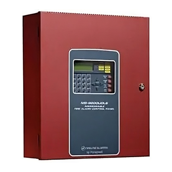
Product Description Features and Options Product Description SECTION 1 The Fire-LiteMS-9200UDLS is a combination FACP (Fire Alarm Control Panel) and DACT (Digital Alarm Communicator/Transmitter) all on one circuit board. This compact, cost effective, intelligent addressable control panel has an extensive list of powerful features. -
Page 13: Specifications
Specifications Product Description • Telephone Line Active LEDs • Communication Confirmation (Kissoff) LED • Touchtone/Rotary dialing • Programmable Make/Break Ratio • EIA-232 Printer/PC interface (variable baud rate) • 80-character LCD display (backlit) • Real-time clock/calendar with daylight savings time control •... - Page 14 Product Description Specifications Battery (Lead Acid Only) - J9 Maximum Charging Circuit: Normal Flat Charge - 27.6 VDC @ 0.80 amp Maximum Battery Charger Capacity: 18 Amp Hour (MS-9200UDLS cabinet holds maximum of two 18 Amp Hour batteries. For greater than 25 Amp Hour up to 120 Amp Hour batteries, use the CHG-75 or CHG-120F Battery Charger and BB-55F Battery Box.
-
Page 15: 1: Current Availability
Specifications Product Description EIA-485 (TERM) or EIA-232 (ACS) - TB8 EIA-485 Terminal Mode annunciator connections: Terminal 1 (Out +), 2 (In +), 3 (Out -), 4 (In -) EIA-232 PC/Printer applications connections: Terminal 1 (Transmit), 2 (Receive), 3 (Ground) EIA-485 (ACS) - TB9 ACS annunciator connector, Terminal 1 (+) and Terminal 2 (-), requires ferrite bead 1.2.1 Current Availability The following figure illustrates the maximum current that is possible for each panel... -
Page 16: Controls And Indicators
Product Description Controls and Indicators 1.3 Controls and Indicators LCD Display The FACP uses an 80-character HONEYWELL LIFE SAFETY (4 lines X 20 characters) high viewing angle LCD display. The SYSTEM ALL NORMAL display includes a long life LED 10:00A 012102 backlight that remains illuminated. -
Page 17: Circuits
Circuits Product Description 1.4 Circuits SLC Communication Loop One SLC loop is provided standard on the FACP main circuit board. The SLC loop, configurable for NFPA Style 4, 6 or 7, provides communication to addressable detectors, monitor (initiating device) and control (output device) modules. Refer to the SLC Wiring manual for information on wiring devices. -
Page 18: Components
Product Description Components 1.6 Components Main Circuit Board The main circuit board contains the system’s CPU, power supply, other primary components and wiring interface connectors. The 4XTMF option module plugs in and is mounted to the main circuit board. Cabinet See Page The MS-9200UDLS backbox provides space for two batteries (up to 18 Amp Hour). -
Page 19: 2: Intelligent Addressable Modules: Newer Series
Components Product Description 1.6.2 Intelligent Addressable Modules: Newer Series The newer series of Control Modules and Monitor Modules provide an interface between the control panel and conventional notification and initiating devices. Each module can be set to respond to an address with built-in rotary switches. The maximum address cannot exceed address 99. -
Page 20: Optional Modules
Product Description Optional Modules 1.7 Optional Modules The MS-9200UDLS main circuit board includes option module connectors for the following module: 4XTMF Transmitter Module The 4XTMF provides a supervised output for local energy municipal box transmitter, alarm and trouble reverse polarity. It includes a disable switch and disable trouble LED. -
Page 21: 3: Battery Box
Accessories Product Description 1.8.3 Battery Box BB-26 The BB-26 battery box may be used to house up to two 26 AH batteries and the CHG-75 Battery Charger. The battery box, which is red and is provided with knockouts, was designed specifically to compliment mounting below the FACP. BB-55F The BB-55F battery box may be used to house two 25 AH batteries, two 60 AH batteries or one 100 AH battery. -
Page 22: 5: Annunciators
Product Description Accessories 1.8.5 Annunciators ACS Series LED Zone Type Annunciators The ACS Series Annunciators remotely display alarm and trouble status as well as system status. In addition, they can provide remote Acknowledge, Silence, Reset and Drill functions. For more detailed information, refer to the appropriate annunciator manual. -
Page 23: Getting Started
Getting Started Product Description LCD-80F Remote Fire Annunciator The LCD-80F annunciator is a compact 80-character backlit LCD remote fire annunciator that is capable of displaying English language text. It mimics the display on the control panel and will annunciate device type, point alarm, trouble or supervisory condition, zone assignment plus any custom alpha labels programmed into the FACP. -
Page 24: Telephone Requirements And Warnings
Product Description Telephone Requirements and Warnings 1.10 Telephone Requirements and Warnings 1.10.1 Telephone Circuitry Ringer Equivalence Number (REN) = 0.0B AC Impedance: 10.0 Mega Ohm Complies with FCC Part 68 Mates with RJ31X Male Connector Supervision Threshold: less than 4.0 volts for 2 minutes The REN is used to determine the quantity of devices which may be connected to the telephone line. -
Page 25: 3: Telephone Company Rights And Warnings
Telephone Requirements and Warnings Product Description 1.10.3 Telephone Company Rights and Warnings The telephone company, under certain circumstances, may temporarily discontinue services and/or make changes in its facilities, services, equipment or procedures which may affect the operation of this control panel. However, the telephone company is required to give advance notice of such changes or interruptions. -
Page 26: 4: For Canadian Applications
Product Description Telephone Requirements and Warnings 1.10.4 For Canadian Applications The following is excerpted from CP-01 Issue 5: NOTICE: The Industry Canada (IC) label identifies certified equipment. This certifica- tion means that the equipment meets certain telecommunications network protective, operational and safety requirements as prescribed in the appropriate Terminal Equip- ment Technical Requirements document(s). -
Page 27: Section 2: Installation
Mounting Backbox Installation Installation SECTION 2 The cabinet may be either semi-flush or surface mounted. The cabinet mounts using two key slots and two 0.250” (6.35 mm) diameter holes located in the backbox. The key slots are located at the top of the backbox and the two securing holes at the bottom. Carefully unpack the system and check for shipping damage. -
Page 28: Mounting Transformer
Installation Mounting Transformer 2.2 Mounting Transformer One XRM-24(E) transformer is supplied standard with the control panel. An optional second XRM-24(E) transformer can be ordered and installed to provide maximum system power. Install the transformers in the locations indicated in the following illustration. - Page 29 Mounting Transformer Installation Semi-Flush Mounting Do not recess box more than 3.875” into wall to avoid covering venting holes on top of box. Figure 2.3 MS-9200UDLS Cabinet Mounting MS-9200UDLS PN 52750:A 11/04/05...
- Page 30 Installation Mounting Transformer Figure 2.4 MS-9200UDLS Cabinet Dimensions MS-9200UDLS PN 52750:A 11/04/05...
-
Page 31: Power
Power Installation 2.3 Power WARNING: Several different sources of power can be connected to this panel. Disconnect all sources of power before servicing. The panel and associated equipment may be damaged by removing and/or inserting cards, modules or interconnecting cables while this unit is energized. 2.3.1 AC Power and Earth Ground Connection Primary power required for the FACP is 120 VAC, LCD DISPLAY... -
Page 32: Relays
Installation Relays 2.4 Relays The FACP provides two programmable Form-C relays and one fixed fail-safe Form-C trouble relay, all with contacts rated for 2.0 amps @ 30 VDC (resistive) or 0.5 amps @ 30 VAC (resistive). Note that relay connections may be power-limited or nonpower-limited, provided that 0.25”... -
Page 33: 1: Configuring Nacs
Notification Appliance Circuits Installation 2.5.1 Configuring NACs The Notification Appliance Circuits on the main circuit board are configured for Style Y (Class B) or Style Z (Class A) by properly orienting the NACKEY card in JP6 which is located at the top of the main circuit board near the NAC terminal blocks TB3 and TB4. -
Page 34: 3: Style Z (Class A) Nac Wiring
Installation Remote Synchronization Output 2.5.3 Style Z (Class A) NAC Wiring 2 Style Z (Class A) Notification Appliance Circuits, supervised and power-limited Polarized Bell Polarized Bell Polarized Strobe Polarized Strobe Polarized Horn Polarized Horn NAC 1 NAC 2 Notification Appliance Circuit polarity shown in alarm state Figure 2.9 NAC Style Z (Class A) Wiring 2.6 Remote Synchronization Output... -
Page 35: Ul Power-Limited Wiring Requirements
UL Power-limited Wiring Requirements Installation 2.7 UL Power-limited Wiring Requirements Power-limited and nonpower-limited circuit wiring must remain separated in the cabinet. All power-limited circuit wiring must remain at least 0.25” (6.35 mm) away from any nonpower-limited circuit wiring and nonpower-limited circuit wiring must enter and exit the cabinet through different knockouts and/or conduits. -
Page 36: Digital Communicator
Installation Digital Communicator 2.8 Digital Communicator Two independent telephone lines can be connected to the control panel. Telephone line control/command is made possible via double line seizure as well as usage of an RJ31X style interconnection. Note that it is critical that the panel's digital communicator be located as the first device on the incoming telephone circuit to properly function. -
Page 37: Optional Module Installation
Optional Module Installation Installation 2.9 Optional Module Installation WARNING! Disconnect all sources of power (AC and DC) before installing or removing any modules or wiring. MS-9200UDLS Keypad/Display Removal Removal of the keypad/display is normally not necessary. If, however, it becomes necessary to replace the keypad/display or access jumpers JP5 and JP7 or switch SW1, the Keypad/Display can be removed by inserting a Phillips screwdriver into each of the three holes located in the flexible covering of the Keypad/Display and loosening the... -
Page 38: 1: 4Xtmf Transmitter Module Installation
Installation Optional Module Installation 2.9.1 4XTMF Transmitter Module Installation The 4XTMF provides a supervised output for a local energy municipal box transmitter in addition to alarm and trouble reverse polarity. A jumper option allows the reverse polarity circuit to open with a system trouble condition if no alarm condition exists. A disable switch allows disabling of the transmitter output during testing to prevent accidental calling of the monitoring service. - Page 39 Optional Module Installation Installation The following steps must be followed when installing the 4XTMF module: 1. Remove all power (Primary and Secondary) from the FACP before installing 4XTMF 2. Cut jumper JP3 on the main circuit board to allow the control panel to supervise the 4XTMF module 3.
-
Page 40: 2: Printer/Pc
Installation Optional Module Installation 2.9.2 Printer/PC A serial printer or a PC (personal computer) may be connected to TB8 Terminals 1 - 4 on the FACP. The printer can be used to provide a hard-copy printout of real-time events, history file and walktest data. An IBM compatible PC can be connected to provide local FACP programming capabilities using the PK-CD programming utility. -
Page 41: 3: Digital Communicator And Annunciators
Optional Module Installation Installation 2.9.3 Digital Communicator and Annunciators 2.9.3.1 ACM-8RF Relay Control Module The ACM-8RF module provides eight Form-C relays with contacts rated for 5 amps. When installed with an MS-9200UDLS FACP, the ACM-8RF modules provide relay activation for each of the 99 possible FACP zones plus special functions. -
Page 42: Section 3: Programming
Programming Programming Data Entry Programming SECTION 3 NOTICE TO USERS, INSTALLERS, AUTHORITIES HAVING JURISDICTION AND OTHER INVOLVED PARTIES This product incorporates field-programmable software. In order for the product to comply with the requirements in the Standard for Control Units and Accessories for Fire Alarm Systems, UL 864, certain programming features or options must be limited to specific values or not used at all as indicated below: Program feature Permitted in... -
Page 43: User Programming
The System All Normal screen will be displayed in a programmed system with no active alarms, troubles or supervisories, as illustrated below: HONEYWELL LIFE SAFETY SYSTEM ALL NORMAL 10:00A 012102 Programming, Read Status and Manual Dial mode can be entered while the panel is in any mode of operation. -
Page 44: Initial Power-Up
Programming Initial Power-up User Programming Levels There are two user programming levels: • User Master Program Level 1 is used for programming panel specific data relating to device types, zoning, messages, control panel functions, etc. • User Maintenance Program Level 2 is used by a qualified operator to access features such as Disable/Enable, View and Clear History, Walktest and System Time Change. - Page 45 Programming and Passwords Programming To access user Programming mode, press the Enter or Mode key. The LCD will display the following: 1=READ STATUS MODE 2=PROGRAMMING MODE 3=MANUAL DIAL MODE To enter the user Programming mode, press 2. The display will read as follows: PROGRAMMING ENTER PASSWORD *****...
-
Page 46: Master Programming Level
Programming Master Programming Level 3.6 Master Programming Level When the Master Program Level password is entered, the control panel will enter user Programming mode. In this mode, the piezo sounder remains off, the trouble relay is activated and the system Trouble LED flashes until Programming mode is exited. The following display will appear: PROGRAMMING 1=AUTOPROGRAM... -
Page 47: 1=Autoprogram
Master Programming Level Programming 3.6.1 Autoprogram PROGRAMMING Pressing 1 while viewing Programming Screen #1, will select the Autoprogram option, 1=AUTOPROGRAM which prompts the control panel to poll all devices installed on the SLC loop. The 2=POINT PROGRAM primary purpose of autoprogramming is to allow the installer a fast and easy way to 3=ZONE SETUP bring the system on-line as quickly as possible. -
Page 48: 2: Point Program
Programming Master Programming Level 3.6.2 Point Program PROGRAMMING The Point Program option allows the programmer to add a new addressable device to an 1=AUTOPROGRAM SLC loop, delete an existing device from a loop or change the programming for an 2=POINT PROGRAM existing device. -
Page 49: Delete Detector
Master Programming Level Programming When the type has been selected, the following screen will be displayed: ADD DETECTOR DETECTOR# IS ADDED The programmer can continue adding detectors by pressing the ESC key which will return the display to the Add Detector Screen. 3.6.2.1.2 Delete Detector Pressing 2 in the Detector Screen will display the Delete Detector Screen which DETECTOR... - Page 50 Programming Master Programming Level If no detectors have been installed on the loop, the following will be displayed: NO DETECTOR INSTALLED Edit Detector Screen #1 If the selected address has been added to programming, device summary screens will be displayed. These screens allow the programmer to view all device settings at a single glance.
- Page 51 Master Programming Level Programming The following examples show the editing of a photoelectric smoke detector with address 017, located on the SLC loop: EDIT DETECTOR 1D017 1=ENABLED 2=TYPE SMOKE(PHOTO) 3=VERIFICATION Edit Detector Screen #2 EDIT DETECTOR 1D017 1=WALKTEST 2=PAS 3=PRE-SIGNAL Edit Detector Screen #3 EDIT DETECTOR 1D017 1=ZONE ASSIGNMENT...
- Page 52 Programming Master Programming Level Type To select the type of detector being programmed, press the 2 key while viewing the EDIT DETECTOR Edit Detector Screen #2. This will cause the control panel to display the following 1=ENABLED 2=TYPE Detector Type Screens: 3=VERIFICATION Edit Detector Screen #2 DETECTOR TYPE...
- Page 53 Master Programming Level Programming The PAS (Positive Alarm Sequence) option will program the detector to delay panel activation (including alarm relay and communicator) for a period of 15 seconds plus a programmable time of up to 3 minutes. Zone 97, however, will activate immediately and may be used to connect a signaling device to indicate PAS activation (do not use a Notification Appliance Circuit for this purpose).
- Page 54 Programming Master Programming Level With the preceding program settings, when the detector with address 005 is activated, zone Z98 will cause its associated control module to activate immediately, sounding the connected signaling device to indicate the Pre-signal condition. Following the Pre-signal delay time, zone Z001 will cause its associated control module to activate and the control panel will initiate an alarm condition.
- Page 55 Master Programming Level Programming Pressing 1 while viewing the Noun/Adjective Screen will cause the following 1=STANDARD ADJECTIVE screen(s) to be displayed. Note that the keyboard down arrow key must be pressed 2=STANDARD NOUN to see all the Adjective screens. Press the number corresponding to the adjective 3=CUSTOM ADJECTIVE that is to be used as a descriptor for the location of the detector currently being 4=CUSTOM NOUN...
- Page 56 Programming Master Programming Level Pressing 2 while viewing the Noun/Adjective Screen will cause the following 1=STANDARD ADJECTIVE screen(s) to be displayed. Note that the keyboard down arrow key must be pressed 2=STANDARD NOUN to see all the Noun screens. Press the number corresponding to the noun that is to 3=CUSTOM ADJECTIVE be used as a descriptor for the location of the detector currently being programmed.
- Page 57 Master Programming Level Programming Pressing 3 or 4 while viewing the Noun/Adjective Screen will display screens 1=STANDARD ADJECTIVE similar to the previous Adjective and Noun Screens. The new screens will list 2=STANDARD NOUN custom Adjectives and Nouns which have been programmed into the control panel 3=CUSTOM ADJECTIVE using the PK-CD programming kit.
-
Page 58: Module Programming
Programming Master Programming Level As an example, the user could quickly enter ‘FLR_3_ROOM_305’ as follows: 1. The cursor is on the first letter of the Adjective field. Press the zero key twice to display FLR_3 2. With the cursor on the first letter of the Noun field, press the zero key twice to recall the display ROOM_304. -
Page 59: Delete Module
Master Programming Level Programming Pressing 1 for Control Module or 2 for Monitor Module will cause the following screen to be displayed: ADD MODULE MODULE# IS ADDED Add Module Screen #3 The programmer can continue adding modules by pressing the ESC or left arrow key which will return the display to the Add Module Screen #1. - Page 60 Programming Master Programming Level A flashing cursor will appear in the position of the first asterisk to the left. The programmer keys in the three digit module address, such as 012. When the last digit is keyed-in, if the selected address has not been added to programming, a screen showing information about the highest address that is installed will be displayed.
- Page 61 Master Programming Level Programming If the selected address corresponds to a control module, a screen displaying information about the control module with the selected address will be displayed as shown in "Edit Module Screen for Control Modules" on page 68. See Page If the selected address corresponds to a monitor module, a screen displaying information about the module with the selected address will be displayed as...
- Page 62 Programming Master Programming Level Enable/Disable Module To Enable or Disable the monitor module, press the 1 key while viewing the Edit Module Screen #2. Each press of the key will toggle the screen between Enabled Yes and Enabled No. If Enabled No is selected, the module will not be polled by the control panel, preventing the module from reporting alarms and troubles to the panel.
- Page 63 Master Programming Level Programming Monitor module type selection will affect the function of the point as follows: Table 3.1 Monitor Types Monitor Type Action When Activated Pull-Station Fire Alarm User-Defined-1 same as previous (Pull-Station) Waterflow Fire Alarm Delayed User-Defined-2 same as previous (Waterflow) Monitor Fire Alarm User-Defined-3...
- Page 64 Programming Master Programming Level Pre-signal EDIT MONITOR 1=PRE-SIGNAL To enable the Pre-signal feature, press 1 while viewing Edit Monitor Screen #3 until the display reads Pre-signal Yes. Each press of the 1 key will cause the display to toggle between Pre-signal Yes and Pre-signal No. Refer to "Presignal" on page 136 Edit Monitor Screen #3 for additional information.
- Page 65 Master Programming Level Programming Pressing 1 while viewing the Noun/Adjective Screen will cause the following 1=STANDARD ADJECTIVE screen(s) to be displayed. Note that the keyboard down arrow key must be pressed 2=STANDARD NOUN to see all the Adjective screens. Press the number corresponding to the adjective 3=CUSTOM ADJECTIVE 4=CUSTOM NOUN that is to be used as a descriptor for the location of the monitor module currently...
- Page 66 Programming Master Programming Level Pressing 2 while viewing the Noun/Adjective Screen will cause the following 1=STANDARD ADJECTIVE screen(s) to be displayed. Note that the keyboard down arrow key must be pressed 2=STANDARD NOUN to see all the Noun screens. Press the number corresponding to the noun that is to 3=CUSTOM ADJECTIVE 4=CUSTOM NOUN be used as a descriptor for the location of the monitor module currently being...
- Page 67 Master Programming Level Programming Description EDIT MONITOR 1=NOUN/ADJECTIVE The Description selection allows the programmer to enter additional information 2=DESCRIPTION about the monitor module currently being programmed. This information will be ***************** displayed as part of the device label on the LCD display. Pressing 2 while viewing Edit Monitor Screen #5 Edit Monitor Screen #5 will cause the following screen to be displayed: DESCRIPTION...
-
Page 68: Edit Module Screen For Control Modules
Programming Master Programming Level As an example, the user could quickly enter ‘FLR_3_ROOM 305’ as follows: 1. The cursor is on the first letter of the Adjective field. Press the zero key twice to display FLR_3 2. With the cursor on the first letter of the Noun field, press the zero key twice to recall the display ROOM_304. - Page 69 Master Programming Level Programming To change the programming for the displayed module, press the keyboard down arrow key to view the following Edit Control screens: EDIT CONTROL 1=ENABLED 2=TYPE CONTROL 3=SILENCEABLE Edit Control Screen #2 EDIT CONTROL 1=WALKTEST 2=ZONE ASSIGNMENT 00 ** ** ** ** Edit Control Screen #3 EDIT CONTROL...
- Page 70 Programming Master Programming Level Type EDIT CONTROL To select the type of control module being programmed, press the 2 key while 1=ENABLED 2=TYPE viewing the Edit Control Screen #2. This will cause the control panel to display the 3=SILENCEABLE following Control Type Screens. Press the down arrow key to view additional Edit Control Screen #2 screens and selections.
- Page 71 Master Programming Level Programming Silenceable EDIT CONTROL 1=ENABLED The Silenceable selection allows the programmer to select whether output devices 2=TYPE connected to the control module can be silenced, either by pressing the Alarm 3=SILENCEABLE Silence key or by enabling Autosilence. Pressing the 3 key while viewing Edit Edit Control Screen #2 Control Screen #2 will enable the Silenceable feature causing the display to read Silenceable Yes.
- Page 72 Programming Master Programming Level Pressing 1 while viewing the Noun/Adjective Screen will cause the following 1=STANDARD ADJECTIVE screen(s) to be displayed. Note that the keyboard down arrow key must be pressed 2=STANDARD NOUN to see all the Adjective screens. Press the number corresponding to the adjective 3=CUSTOM ADJECTIVE 4=CUSTOM NOUN that is to be used as a descriptor for the location of the control module currently...
- Page 73 Master Programming Level Programming Pressing 2 while viewing the Noun/Adjective Screen will cause the following 1=STANDARD ADJECTIVE screen(s) to be displayed. Note that the keyboard down arrow key must be pressed 2=STANDARD NOUN to see all the Noun screens. Press the number corresponding to the noun that is to 3=CUSTOM ADJECTIVE 4=CUSTOM NOUN be used as a descriptor for the location of the control module currently being...
- Page 74 Programming Master Programming Level Description EDIT CONTROL 1=ADJECTIVE/NOUN The Description selection allows the programmer to enter additional information 2=DESCRIPTION about the control module currently being programmed. This information will be displayed as part of the device label on the display. Pressing 2 while viewing Edit Edit Control Screen #4 Control Screen #4 will cause the following screen to be displayed: DESCRIPTION...
-
Page 75: 3=Zone Setup
Master Programming Level Programming 3.6.3 Zone Setup PROGRAMMING 1=AUTOPROGRAM Pressing 3 while viewing Programming Screen #2 will access the Zone Setup screens as 2=POINT PROGRAM illustrated below: 3=ZONE SETUP Programming Screen #2 ZONE SETUP 1=ENABLE 2=DISABLE 3=ZONE 97 98 99 Zone Setup Screen #1 ZONE SETUP 1=ZONES INSTALLED... -
Page 76: Disable
Programming Master Programming Level 3.6.3.2 Disable ZONE SETUP Pressing 2 for Disable, while viewing Zone Setup Screen #1, displays the following: 1=ENABLE 2=DISABLE 3=ZONE 97 98 99 ZONE TO DISABLE Zone Setup Screen #1 Disable Screen This screen allows the programmer to disable zones, one at a time. A flashing cursor appears next to the Z, prompting the programmer to enter a two digit zone number (01 - 99). -
Page 77: Zones Installed
Master Programming Level Programming 3.6.3.4 Zones Installed ZONE SETUP Pressing 1 for Zones Installed, while viewing Zone Setup Screen #2, will display a 1=ZONES INSTALLED screen similar to the following: 2=ZONES ENABLED 3=ZONES DISABLED Zone Setup Screen #2 ZONES INSTALLED 00 01 02 03 04 05 Zones Installed Screen This display will show all of the zones that have been programmed into the control... -
Page 78: Zone Type
Programming Master Programming Level 3.6.3.7 Zone Type ZONE SETUP Zone Types must be programmed only if a DACT, programmed for zone reporting, 1=ZONE TYPES is installed on the control panel. Pressing 1 for Zone Types, while viewing Zone 2=ZONES AVAILABLE 3=ZONE MESSAGE Setup Screen #3, will display a screen similar to the following: Zone Setup Screen #3... -
Page 79: Zones Available
Master Programming Level Programming 3.6.3.8 Zones Available ZONE SETUP Pressing 2 while viewing Zone Setup Screen #3 will display a screen similar to the 1=ZONE TYPES following: 2=ZONES AVAILABLE 3=ZONE MESSAGE Zone Setup Screen #3 ZONES AVAILABLE 01 02 03 04 05 06 07 08 09 10 11 12 13 14 15 16 17 18 19 20 21 The display will show all of the zones that are still available for programming. -
Page 80: 5: System Setup
• Banner: This option allows the user to change the top two lines of the LCD display from the factory default readout of HONEYWELL LIFE SAFETY to a user defined readout when the control panel is in Normal condition. •... -
Page 81: Trouble Reminder
2=USER DEFINED setting and display the following screen: Banner Screen FACTORY BANNER HONEYWELL LIFE SAFETY Factory Banner Screen Pressing the Enter key will store this selection in nonvolatile memory and return the display to the Banner Screen. Pressing 2 while viewing the Banner Screen will cause the following screens to be... -
Page 82: Time-Date
Programming Master Programming Level to view the second screen. Enter up to 20 characters in the second screen in the same manner or just press Enter if a second banner line is not being entered. To quickly clear the current banner, press the CLR key. To enter alphanumeric characters from the keypad, repeatedly press the appropriate key until the desired character is displayed in the first position. -
Page 83: Date
Master Programming Level Programming 3.6.5.3.2 Date To change the date, press 2 while viewing the Time-Date Screen. The following screen will be displayed: ENTER DATE MONTH DAY YEAR 04-07-2002 Date Screen A flashing cursor is located toward the top left of the display. Below the cursor is the current date. -
Page 84: Timers
Programming Master Programming Level Pressing 3 while viewing Daylight Savings Screen #1 will display two sub-screens which allow the programmer to select the week of the month that daylight savings time will begin. In the first sub-screen, pressing 1 will select the first week, 2 will select the second week and 3 will select the third week, while in the second sub- screen, pressing 1 will select the fourth week and 2 will select the last week of the selected month. -
Page 85: Presignal Delay
Master Programming Level Programming 3.6.5.4.2 Pre-signal Delay The factory default setting for Pre-signal delay is 000 for no delay. To select a Pre- signal delay of 001 to 180 seconds for all devices programmed for Pre-signal, press 2 while viewing Timer Screen #1. The following screen will be displayed: PRESIGNAL DELAY RANGE 0-180 SECONDS Pre-signal Delay Screen... -
Page 86: Ac Loss Delay
Programming Master Programming Level 3.6.5.4.4 AC Loss Delay TIMER The reporting of a loss of AC power to a central station can be delayed by 1=AC LOSS DELAY programming the length of the desired delay. Press 1 while viewing Timer Screen #2 to display the following: Timer Screen #2 AC LOSS DELAY... -
Page 87: Enabled
Master Programming Level Programming The following screens will be displayed for each selection: NAC # 1=ENABLED 2=TYPE BELL 3=SILENCEABLE NAC Screen #1 NAC # 1=AUTO SILENCE 2=CODING TEMPORAL NAC Screen #2 NAC # 1=ZONE 00 00 00 00 00 2=SIL INHIBITED NAC Screen #3 NAC # 1=SYNC TYPE... -
Page 88: Type
Programming Master Programming Level 3.6.5.5.2 Type NAC # The main circuit board NAC type can be programmed by pressing 2 while viewing 1=ENABLED NAC Screen #1. The following screen will be displayed. Press the down arrow key 2=TYPE 3=SILENCEABLE to view additional screens: NAC Screen #1 NAC TYPE 1=BELL... -
Page 89: Auto Silence
Master Programming Level Programming 3.6.5.5.4 Auto Silence NAC # The Auto Silence feature, when enabled, automatically silences all main circuit 1=AUTO SILENCE board silenceable notification appliances after a programmed length of time. To 2=CODING TEMPORAL enable this feature and program the time delay before Auto Silence activation, press NAC Screen #2 1 while viewing NAC Screen #2. - Page 90 Programming Master Programming Level The programmer can select the notification appliance output by pressing the number corresponding to the desired output. The coding selections are: • Steady - a continuous output with no coding • March Time - 120 ppm (pulse-per-minute) output •...
-
Page 91: Zone
Master Programming Level Programming 3.6.5.5.6 Zone NAC # A maximum of five zones can be programmed to each main circuit board NAC. 1=ZONE Pressing 1 while viewing NAC Screen #3 displays the following screen: 00 00 00 00 00 2=SIL INHIBITED NO NAC Screen #3 ZONE ASSIGNMENT Z00 Z** Z** Z** Z**... -
Page 92: Relays
Programming Master Programming Level 3.6.5.6 Relays SYSTEM SETUP Pressing 3 while viewing System Setup Screen #2 will allow the programmer to 1=TIMERS configure two of the three main circuit board Form-C relays. The following screen 2=NAC 3=RELAYS will be displayed: System Setup Screen #2 RELAYS 1=RELAY 1... -
Page 93: Canadian Option
Master Programming Level Programming 3.6.5.7 Canadian Option SYSTEM SETUP Pressing 1 while viewing System Setup Screen #3 will allow the programmer to 1=CANADIAN OPT. OFF configure the system to automatically monitor addressable ionization smoke 2=WATERFLOW SIL. NO detector sensitivity using Canadian specifications. The display will change to System Setup Screen #3 Canadian Opt. -
Page 94: 7: History
Programming Master Programming Level 3.6.7 History PROGRAMMING The History option allows an authorized user to view or erase events which have 1=HISTORY occurred in the control panel. Pressing 1 while viewing Programming Screen #3 will 2=WALKTEST display the History options as shown in the following display: 3=OPTION MODULES Programming Screen #3 HISTORY... -
Page 95: 8: Walktest
Master Programming Level Programming 3.6.8 Walktest PROGRAMMING Walktest allows an individual to test the fire alarm system without the necessity to reset 1=HISTORY the control panel after each device activation. Pressing 2 while viewing the 2=WALKTEST Programming Screen #3 will cause the following Walktest options to be displayed: 3=OPTION MODULES Programming Screen #3 WALKTEST... -
Page 96: 9: Option Modules
Programming Master Programming Level 3.6.9 Option Modules PROGRAMMING Options available for the MS-9200UDLS include ACS Series, Graphic and LCD 1=HISTORY annunciators, printer connection for acquiring hardcopy printouts of panel data and PC 2=WALKTEST (Personal Computer) connection for uploading and downloading panel data. 3=OPTION MODULES Pressing 3 while viewing Programming Screen #3 will display the following screen: Programming Screen #3... -
Page 97: Onboard Dact
Master Programming Level Programming If an ACS annunciator is installed, press 1 while viewing Annunciator Screen #2 to select addresses for the ACS annunciators. The following screen will be displayed: ANNUNCIATOR 1=ADDRESS 1 2=ADDRESS 2 3=ADDRESS 3 ACS Installed Screen Pressing the down arrow key will allow the programmer to view additional screens displaying Addresses 1 -31. -
Page 98: Primary Phone
Programming Master Programming Level 3.6.9.2.2 Primary Phone Press 2 while viewing On Board DACT Screen #1 to program the type of primary phone line being connected to the DACT. The following screen will be displayed: ON BOARD DACT PRIMARY PHONE LINE 1=TYPE TOUCHTONE Primary Phone Line Screen... -
Page 99: Service Terminal
Master Programming Level Programming 3.6.9.2.4 Service Terminal The MS-9200UDLS can be programmed remotely from a PC using a modem and ON BOARD DACT telephone line. Information can also be retrieved from the FACP using the same 1=SERVICE TERMINAL 2=CENTRAL STATION method. - Page 100 Programming Master Programming Level 3.6.9.2.4.2 Terminal 1 and Terminal 2 Service Terminal #1 is generally designated as the FACP primary phone line used SERVICE TERMINAL for receiving phone calls from the service terminal (PC) being used for remote 1=PANEL ID 2=TERMINAL 1 programming.
-
Page 101: Central Station
Master Programming Level Programming 3.6.9.2.4.3 Ring Count The ring count designates the number of rings allowed on the phone line prior to SERVICE TERMINAL answering an incoming call from a service terminal. The factory default is 3 which 1=RING COUNT means the control panel will not answer an incoming call until 3 rings are detected. -
Page 102: Trouble Call Limit (Dialer Runaway Prevention)
Programming Master Programming Level 3.6.9.2.5.2 Backup Reporting The DACT can be programmed to transmit reports to primary and/or secondary central station phone numbers as a backup. Press 2 while viewing Central Station Screen #1 to display the following screen: BACKUP REPORTING 1=BACKUP ONLY 2=BOTH 3=FIRST AVAILABLE... - Page 103 Master Programming Level Programming 3.6.9.2.6.1 Central Station Primary and Secondary Phone Numbers Pressing 1 for Primary or 2 for Secondary will display the following screens. CENTRAL STATION 1=PRIMARY Note that the following information must be entered for both the Primary and 2=SECONDARY Secondary Central Station Phone Numbers.
- Page 104 Programming Master Programming Level Test Time Interval CENTRAL STATION Pressing 1 while viewing Primary/Secondary Screen #1 will cause the following 1=TEST TIME INT screens to be displayed: 2=ACCOUNT CODE 3=24HR TST TIME Primary/Secondary Screen #1 TEST TIME INTERVAL 1=24 HOURS 2=12 HOURS 3=8 HOURS Test Time Interval Screen #1...
- Page 105 Master Programming Level Programming 24 Hour Test Time CENTRAL STATION Pressing 3 while viewing Primary/Secondary Screen #1 will cause the following 1=TEST TIME INT screen to be displayed: 2=ACCOUNT CODE 3=24HR TST TIME 24 HOUR TEST TIME Primary/Secondary Screen #1 RANGE 0000-2359 24 Hour Test Time Screen Use the 24 Hour Test Time screen to program the time that the DACT will transmit...
- Page 106 Programming Master Programming Level Communication Format CENTRAL STATION Pressing 1 while viewing Primary/Secondary Screen #3 will cause the following 1=COMM FORMAT screens to be displayed: COMM FORMAT Primary/Secondary Screen #3 1=ADEMCO EXPRESS 4P1 2=ADEMCO EXPRESS 4P2 3=3P1S C18 A23 Comm Format Screen #1 COMM FORMAT 1=3P1E C18 A23 2=3P1S C19 A14...
- Page 107 Master Programming Level Programming The Communication Format is determined by the type of receiver that the DACT is transmitting to. Consult your Central Station for proper selection or consult our factory representatives. For any format chosen, the control panel automatically programs all of the event codes.
- Page 108 Programming Master Programming Level 3+1, 4+1 Express and 4+1 Standard The information shown in Table 3.2 is automatically programmed for the Central Station phone number Event Codes when any of these Formats are selected. Enter 0 for an Event Code Setting to disable the report. Table 3.2 Event Codes Event Description Event Code Settings...
- Page 109 Master Programming Level Programming Table 3.2 Event Codes (continued) MON-USER-DEF-16 PROCMON AR MON-USER-DEF-17 not used not used POINT_FAULT POINT_DISABLE AC_FAIL DRILL SLC OPEN FAULT SLC SHORT FAULT not used not used GROUND FAULT LOW BATTERY NO_BATTERY TELCO LINE 1 TELCO LINE 2 COMM FAULT 1 COMM FAULT 2 TOTAL COMM FLT...
- Page 110 Programming Master Programming Level 4+2 Standard, 4+2 Express, 3 + 1, 4 + 1 and 4+2 Expanded Formats The information shown in Table 3.3 is automatically programmed for the Central Station phone number Event Codes when any of these Formats are selected. Enter 00 for an Event Code Setting to disable the report.
- Page 111 Master Programming Level Programming Table 3.3 Event Codes (continued) MON-USER-DEF-16 PROCMON AR MON-USER-DEF-17 not used not used POINT_FAULT POINT_DISABLE AC_FAIL DRILL SLC OPEN FAULT SLC SHORT FAULT not used not used GROUND FAULT LOW BATTERY NO_BATTERY TELCO LINE 1 TELCO LINE 2 COMM FAULT 1 COMM FAULT 2 TOTAL COMM FLT...
- Page 112 Programming Master Programming Level Ademco Contact ID Format The information shown in Table 3.4 is automatically programmed for the Central Station phone number Event Codes when Ademco Contact ID Format is selected. Enter 000 for an Event Code Setting to disable the report. Table 3.4 Event Codes Event Description Event Code Settings...
- Page 113 Master Programming Level Programming Table 3.4 Event Codes (continued) MON-USER-DEF-16 PROCMON AR MON-USER-DEF-17 not used not used POINT_FAULT POINT_DISABLE AC_FAIL DRILL SLC OPEN FAULT SLC SHORT FAULT not used not used GROUND FAULT LOW BATTERY NO_BATTERY TELCO LINE 1 TELCO LINE 2 COMM FAULT 1 COMM FAULT 2 TOTAL COMM FLT...
-
Page 114: Manual Dial Mode
Programming Master Programming Level Report Style CENTRAL STATION Pressing 3 while viewing Central Station Screen #2 will cause the Report Style 1=PRIMARY display to toggle between Point and Zone. Setting the Report Style to Point will 2=SECONDARY program the DACT to report individual point status to the Central Station. The 3=REPORT STYLE POINT control panel is capable of monitoring a total of 198 addressable devices. -
Page 115: Printer/Pc
Master Programming Level Programming 3.6.9.3 Printer/PC A Printer or a PC can be connected to the control panel. Pressing 3 while viewing OPTION MODULES 1=ANNUNCIATORS/UDACT the Option Module Screen will cause the following screen to appear: 2=ON BOARD DACT 3=PRINTER/PC PRINTER-PC Option Module Screen 1=PRINTER NO SU... -
Page 116: 10: Password Change
Programming Master Programming Level 3.6.10 Password Change PROGRAMMING The factory set passwords, which have been programmed into the control panel, can be 1=PASSWORD CHANGE changed by selecting the Password Change option. Pressing 1 while viewing 2=CLEAR PROGRAM Programming Screen #4 will cause the following screen to be displayed: 3=PROGRAM CHECK Programming Screen #4 PASSWORD CHANGE... -
Page 117: 11: Clear Program
Master Programming Level Programming 3.6.11 Clear Program PROGRAMMING Pressing 2 while viewing Programming Screen #4, will select the Clear Program 1=PASSWORD CHANGE option. This will cause the LCD to display the following screen: 2=CLEAR PROGRAM 3=PROGRAM CHECK Programming Screen #4 CLEAR PROGRAM 1=WHOLE SYSTEM 2=ALL POINTS... -
Page 118: 12: Program Check
Programming Master Programming Level 3.6.12 Program Check PROGRAMMING The Program Check feature allows the programmer to view the zones which have been 1=PASSWORD CHANGE programmed to the Notification Appliance Circuits on the control panel but have not 2=CLEAR PROGRAM been programmed to Initiating Devices as well as other circuits with no input or output 3=PROGRAM CHECK correlations. - Page 119 Master Programming Level Programming Pressing 2 while viewing the Program Check screen will display a screen similar to the following: ZONES NO INPUT 05 07 09 10 11 1M001 The Zone No Input screen allows the programmer to view the zones which have not been programmed to at least one input device (not including general alarm Zone 00).
-
Page 120: Maintenance Programming Level
Programming Maintenance Programming Level 3.7 Maintenance Programming Level To access Maintenance Programming mode, press the Enter key. The LCD will display the following: 1=READ STATUS 2=PROGRAMMING To enter the Maintenance Programming mode, press 2. The display will read as follows: PROGRAMMING ENTER PASSWORD When the Maintenance level password (default 11111) is entered, the following screen... -
Page 121: 1: Disable Point
Maintenance Programming Level Programming 3.7.1 Disable Point PROGRAMMING Pressing 1 for Point Program, while viewing Maintenance Screen #1 will cause the 1=POINT PROGRAM following screens to be displayed: 2=HISTORY 3=PROGRAM CHECK Maintenance Screen #1 POINT PROGRAM 1=DETECTOR 2=MODULE Device Select Screen Select the device type by pressing 1 for an addressable detector or 2 for an addressable module. -
Page 122: 2=History
Programming Maintenance Programming Level 3.7.2 History PROGRAMMING Pressing 2 while viewing Maintenance Screen #1 will cause the following screen to be 1=POINT PROGRAM displayed: 2=HISTORY 3=PROGRAM CHECK Maintenance Screen #1 HISTORY 1=VIEW EVENTS 2=ERASE HISTORY History Screen The History feature allows the operator to view control panel events which have been stored in a history file in memory and erase the contents of the history file Pressing 1 while viewing the History screen will cause the following screen to be displayed:... -
Page 123: 3: Program Check
Maintenance Programming Level Programming 3.7.3 Program Check PROGRAMMING Pressing 3 while viewing Maintenance Screen #1 will cause the following screen to be 1=POINT PROGRAM displayed: 2=HISTORY 3=PROGRAM CHECK Maintenance Screen #1 PROGRAMCHECK 1=NACS NO INPUT 2=ZONES NO INPUT 3=ZONE NO OUTPUT Program Check Screen The Program Check feature allows the programmer to view the zones which have been programmed to the Notification Appliance Circuits on the control panel but have not... -
Page 124: 4: Walktest
Programming Maintenance Programming Level Pressing 3 while viewing Program Check screen will cause a screen similar to the following to be displayed: ZONES NO OUTPUT 05 07 09 10 11 1D001 The Zone No Output feature allows the programmer to view the zones which have not been programmed to at least one output device (not including general alarm Zone 00). - Page 125 Maintenance Programming Level Programming Pressing 1 while viewing the System Screen will cause the following screen to be displayed: TIME AND DATE 1=TIME 01:00 AM 2=DATE 01-01-2001 12HR Time and Date Screen To change the time, press 1 to display the following screen: ENTER TIME 01:00 AM 1=AM...
-
Page 126: 6: Zone Setup
Programming Maintenance Programming Level 3.7.6 Zone Setup PROGRAMMING Pressing 3 while viewing Maintenance Screen #2 will display the following screen: 1=WALKTEST 2=SYSTEM 3=ZONE SETUP Maintenance Screen #2 ZONE SETUP 1=ENABLE 2=DISABLE 3=ZONE 97 98 99 Zone Setup Screen Pressing 1 while viewing Zone Setup screen will display the following screen: ZONE TO ENABLE Enable Screen A flashing cursor appears to the right of the Z. - Page 127 Maintenance Programming Level Programming Pressing 3 while viewing Zone Setup screen will display the following screen: SPEC PURPOSE ZONE 1=PAS 97 2=PRE-SIGNAL 98 3=TWO STAGE 99 Disable Screen Zones 97, 98 and 99 can be programmed for normal zone operation or for special purpose applications.
-
Page 128: Section 4: Operating Instructions
Operating Instructions Panel Control Buttons Operating Instructions SECTION 4 4.1 Panel Control Buttons 4.1.1 Acknowledge/Step The first press of the Acknowledge/Step key silences the piezo sounder, changes flashing LEDs to steady and also changes the status field on the LCD display from capital letters to small letters. -
Page 129: Led Indicators
LED Indicators Operating Instructions 4.2 LED Indicators The nine LED indicators, which are located on the front panel, operate as follows: AC Power This is a green LED which illuminates if AC power is applied to the FACP. A loss of AC power will turn off this LED Fire Alarm This red LED flashes when one or more alarms occur. -
Page 130: Normal Operation
With no alarms or troubles in the system, the display message is System All Normal along with the current time and date as shown below. To set the time and date, refer to the appropriate section in this manual. HONEYWELL LIFE SAFETY SYSTEM ALL NORMAL 10:00A 012102... - Page 131 Trouble Operation Operating Instructions Addressable Smoke Detectors, Monitor Modules and Control Modules For addressable devices connected to the SLC loop, the following is a typical message that could appear on the LCD display for a device trouble: TROUBL SMOKE (PHOTO) <ADJ>...
-
Page 132: Alarm Operation
Operating Instructions Alarm Operation Pressing the Acknowledge/Step or Alarm Silence key will cause the pulsing piezo to silence and the system Trouble LED to change from flashing to on steady. This block acknowledgment occurs regardless of the number of troubles, alarms and supervisory events active in the system. -
Page 133: Supervisory Operation
Supervisory Operation Operating Instructions • Second line in display: <ADJ>; refers to the user programmed adjective descriptor from library list resident in the control panel or custom entry via PC. <NOUN>; refers to the user programmed noun descriptor from library list resident in the control panel or custom entry via PC. -
Page 134: Process Monitor Operation
Operating Instructions Process Monitor Operation 4.7 Process Monitor Operation Process Monitor operation will initiate the following events: • The piezo sounder pulses ¼ second On and ¼ second Off • The LCD displays a process monitor message along with the device name, type, address, adjective/noun, associated zones and time/date •... -
Page 135: Programmed Zone Operation
Programmed Zone Operation Operating Instructions 4.11 Programmed Zone Operation Each addressable detector and monitor module can be assigned to a maximum of five software alarm zones. A general alarm zone Z00 may be listed for output (control) points, but it is not necessary to list Z00 for input points, since this is the default zone for all alarm input devices. -
Page 136: Synchronized Nac Operation
Operating Instructions Synchronized NAC Operation 4.16 Synchronized NAC Operation Synchronization is a panel feature that controls the activation of notification appliances in such a way that all devices will turn on and off at exactly the same time. This is particularly critical when activating strobes which must be synchronized to avoid random activation and a potential hazard or confusion. -
Page 137: Positive Alarm Sequence
Positive Alarm Sequence Operating Instructions 4.19 Positive Alarm Sequence PAS (Positive Alarm Sequence) option will program a smoke detector to delay panel activation (including alarm relay and communicator) for a period of 15 seconds. Zone 97, however, will activate immediately and may be used to connect a signaling device to indicate PAS activation. -
Page 138: Special System Timers
Operating Instructions Special System Timers 4.20 Special System Timers 4.20.1 Silence Inhibit Timer This option, if selected, prevents the Alarm Silence key from functioning for 60 seconds following an alarm. A new alarm during the initial 60 second period will not cause the timer to restart with a new 60 seconds. -
Page 139: 5: Alarm Verification (None Or One Minute)
Walktest Operating Instructions 4.20.5 Alarm Verification (None or One Minute) If alarm verification is selected, an addressable smoke detector's alarm is ignored for a retard time of 13 seconds and the detector's alarm condition is automatically reset. There will be no alarm indication at the FACP during the Retard period. -
Page 140: Read Status
Operating Instructions Read Status 4.22 Read Status Read Status functions do not require a password. The control panel will continue to provide fire protection while in Read Status mode. This mode can be entered while the control panel is in alarm or trouble. -
Page 141: 1: System Point
Read Status Operating Instructions 4.22.1 System Point READ STATUS Pressing 1 while viewing Read Status Screen #1 will cause the following screen to be displayed: 1=SYSTEM POINT 2=ZONES 3=POWER READ SYSTEM POINT Read Status Screen #1 SELECT TYPE 1=DETECTOR 2=MODULE The operator selects the type of device which is to be viewed by pressing 1 for Detector or 2 for Module. -
Page 142: 2: Zones
Operating Instructions Read Status Pressing the down arrow key, while viewing the screen shown above, will allow the operator to view additional programming information about the selected device, such • Enable/Disable Status • Device Type • Alarm Verification On/Off (for detectors) •... -
Page 143: 3: Power
Read Status Operating Instructions 4.22.3 Power Pressing 3 while viewing Read Status Screen #1 will cause the following screens to be displayed: POWER BATTERY 27.21V 24 V RST 25.31 Power Screen #1 POWER CHARGER 28.36V NAC 1 -1.49V NAC 2 -1.49V Power Screen #2 POWER... -
Page 144: 4: Trouble Reminder
Operating Instructions Read Status 4.22.4 Trouble Reminder READ STATUS Pressing 1 while viewing Read Status Screen #2 will display the following screen: 1=TROUBLE REMINDER 2=TIMERS 3=NAC Read Status Screen #2 TROUBLE REMINDER TROUBLE REM The screen indicates whether the Trouble Reminder feature is On or Off. 4.22.5 Timers Pressing 2 while viewing Read Status Screen #2 will cause the following Timer screens to be displayed:... -
Page 145: 6: Nac
Read Status Operating Instructions 4.22.6 NAC Pressing 3 while viewing Read Status Screen #2 will display the following screen: 1=NAC 1 3=NAC 3 2=NAC 2 4=NAC 4 Note that 3=NAC 3 and 4=NAC 4 will always be displayed regardless of how the NACKEY NAC option card is installed. -
Page 146: 8: Program Check
Operating Instructions Read Status 4.22.8 Program Check Pressing 2 while viewing Read Status Screen #3 will cause a screen similar to the following to be displayed: PROGRAM CHECK 1=NACS NO INPUT 2=ZONES NO INPUT 3=ZONES NO OUTPUT Pressing 1 while viewing the Program Check screen will display a screen which will indicate if any input zones have not been programmed to one of the Notification Appliance Circuits. -
Page 147: 10: Annunciators
Read Status Operating Instructions 4.22.10 Annunciators READ STATUS Pressing 1 while viewing Read Status Screen #4 will display the following screens: 1=ANNUNCIATORS 2=PHONE LINE 3=CENTRAL STATION ANNUNCIATORS Read Status Screen #4 TERM ENABLED ACS ENABLED UDACT ENABLED Annunciator Screen #1 ANNUNCIATORS 1=ACS ADDRESS Annunciator Screen #2... -
Page 148: 12: Central Station
Operating Instructions Read Status 4.22.12 Central Station READ STATUS Pressing 3 while viewing Read Status Screen #4 will display the following screens: 1=ANNUNCIATORS 2=PHONE LINE 3=CENTRAL STATION Read Status Screen #4 CENTRAL STATION REPORTING ENABLED REPORT BOTH CALL LIMIT Central Station Screen #1 CENTRAL STATION 1=PRIMARY 2=SECONDARY... -
Page 149: 13: Service Terminal
Read Status Operating Instructions 4.22.13 Service Terminal READ STATUS Pressing 1 while viewing Read Status Screen #5 will display the following screens: 1=SERVICE TERMINAL 2=PRINTER/PC 3=PRINT SERVICE TERMINAL Read Status Screen #5 PANEL ID 2=TERMINAL 1 3=TERMINAL 2 Service Terminal Screen #1 SERVICE TERMINAL RING COUNT Service Terminal Screen #2... -
Page 150: 15: Print
Operating Instructions Read Status 4.22.15 Print READ STATUS To print program data or control panel status, press 3 while viewing Read Status Screen 1=SERVICE TERMINAL #5. The following screens will be displayed: 2=PRINTER/PC 3=PRINT Read Status Screen #5 PRINT 1=HISTORY 2=WALKTEST LOG 3=DETECTOR DATA Print Screen #1... - Page 151 Read Status Operating Instructions Drift Compensation Drift compensation uses software algorithms that identify and compensate for long- term changes in the data readings from each addressable smoke detector. These long- term changes in detector data readings are typically caused by dirt and dust accumulation inside the smoke chamber.
-
Page 152: 16: Time-Date
Operating Instructions Read Status 4.22.16 Time-Date READ STATUS The operator can view the daylight savings time and the month and week when daylight 1=TIME-DATE savings time will begin and end. Pressing 1 while viewing Read Status Screen #6 will display the following screens: Read Status Screen #6 DAYLIGHT SAVINGS ENABLED... -
Page 153: Section 5: Central Station Communications
Read Status Central Station Communications Central Station Communications SECTION 5 The control panel transmits zone and system status reports to Central Stations via the public switched telephone network. Two supervised telephone line connections are made to interface the control panel to the telephone lines. Two optional 7 foot telephone cords are available for this purpose and can be purchased separately. - Page 154 Central Station Communications Read Status The control panel is capable of reporting detailed messages depending upon the format in use. Table 5.1 shows the reporting structure for all formats. Table 5.1 Format Selection Format Format Format Format Report 3+1/4+1/Standard 3+1/4+1/Expanded 4+2/Standard 4+2/Expanded 4+1 Express...
- Page 155 Read Status Central Station Communications Table 5.2 Format Selection Address Explanation Where SSS or SSSS Subscriber ID Alarm (1st digit) Alarm (2nd digit) Zone Number Alarm Restore (1st digit) Alarm Restore (2nd digit) Zone Trouble (1st digit) Zone Trouble (2nd digit) Zone Trouble Restore (1st digit) RTZ2 Zone Trouble Restore (2nd digit)
-
Page 156: Transmittal Priorities
Central Station Communications Transmittal Priorities 5.1 Transmittal Priorities The integral communicator transmits highest priority events first. Events, in terms of priority, are listed below in descending order: 1. Alarms (highest priority level) Pull stations Waterflow Smoke detector Other alarm types 2. - Page 157 Transmittal Priorities Central Station Communications 9200UDLS. Table 5.3 Compatible UL Listed Receivers Format # (Addresses 16 & 42) 4+1 Ademco Express 4+2 Ademco Express 3+1/Standard/1800/2300 3+1/Expanded/1800/2300 3+1/Standard/1900/1400 3+1/Expanded/1900/1400 4+1/Standard/1800/2300 4+1/Expanded/1800/2300 4+1/Standard/1900/1400 4+1/Expanded/1900/1400 4+2/Standard/1800/2300 4+2/Expanded/1800/2300 4+2/Standard/1900/1400 4+2/Expanded/1900/1400 Ademco Contact ID Not Used 1.
-
Page 158: Section 6: Remote Site Upload/Download
Remote Site Upload/Download Downloading Program Remote Site Upload/Download SECTION 6 The control panel may be programmed or interrogated off-site via the public switched telephone network. Any personal computer with Windows ™ 95 or greater, with a 14.4 Kbaud compatible modem and Upload/Download software kit P/N PK-CD, may serve as a Service Terminal. -
Page 159: 1: Security Features
Downloading Program Remote Site Upload/Download Anytime a download with callback is initiated, the first thing the control panel will do is one of the following: • contact the primary Central Station • contact the primary and secondary Central Stations • contact the first available Central Station phone number Once contact has been established, the control panel will report a ‘request for upload/ download’... - Page 160 Remote Site Upload/Download Downloading Program Panel Identification Number The panel identification number is typically used to identify the panel to the Service Terminal when the control panel calls the Service Terminal. If more than one call comes into the Service Terminal, the control panel ID number is used to sort out the calling parties.
-
Page 161: Downloading Initiated At A Service Terminal
Downloading Initiated at a Service Terminal Remote Site Upload/Download 6.2 Downloading Initiated at a Service Terminal Before initiating the download procedure, make certain that the control panel is: In Normal Mode Central Station communications are off The communicator is in the standby state (red phone line active LEDs are off and Kissoff LEDs are off) Once the control panel accepts/answers an incoming call, the panel will: 1. -
Page 162: Uploading Initiated At A Service Terminal
Remote Site Upload/Download Uploading Initiated at a Service Terminal 6.3 Uploading Initiated at a Service Terminal Items that may be uploaded from the control panel to a Service Terminal are: • All programmed data plus the real-time clock, time and date •... -
Page 163: Section 7: Power Supply Calculations
Overview Power Supply Calculations Power Supply Calculations SECTION 7 7.1 Overview This section contains instructions and tables for calculating power supply currents in alarm and standby conditions. This is a four-step process, consisting of the following: 1. Calculating the total amount of AC branch circuit current required to operate the system 2. -
Page 164: Calculating The System Current Draw
Power Supply Calculations Calculating the System Current Draw 7.3 Calculating the System Current Draw 7.3.1 Overview The control panel must be able to power all internal and external devices continuously during the non-fire alarm condition. To calculate the non-fire alarm load on the system power supply when primary power is applied, use Calculation Column 1 in Table 7.3 on page 165. - Page 165 Calculating the System Current Draw Power Supply Calculations Table 7.3 contains columns for calculating current draws. For each column, calculate the current and enter the total (in amperes) in the bottom row. When finished, copy the totals from Calculation Column 2 and Calculation Column 3 to Table 7.4 on page 166. Table 7.3 System Current Draw Calculations Calculation Column 1 Calculation Column 2...
-
Page 166: Calculating The Battery Size
Power Supply Calculations Calculating the Battery Size 7.4 Calculating the Battery Size Use Table 7.4 to calculate the total Standby and Alarm load in ampere hours (AH). This total load determines the battery size (in AH), required to support the control panel under the loss of AC power. -
Page 167: Appendix A: Software Zones
Correlations Software Zones Software Zones APPENDIX A A.1 Correlations Setup and configuration of an addressable system is different than a conventional system. In a conventional system, assignment of input devices (smoke detectors, pull stations, heat detectors, etc.) to zones is accomplished through wiring. The wiring is direct from clearly marked panel terminals to any device assigned to a particular zone. - Page 168 Software Zones Correlations Correlation of Input and Output Zones Input Devices Zones Output Devices SD350 CMF-300 SD350 CMF-300 ZONE MMF-300 CMF-300 MMF-302 CMF-300 CMF-300 MMF-302 CMF-300 CP350 ZONE CMF-300 CP300 SD350 CMF-300 SD350 ZONE SD350 CMF-300 MMF-302 The zone correlations which are shown graphically above are also presented in Table A.1 on page 169 and Table A.2 on page 170.
- Page 169 Correlations Software Zones Table A.1 Detector Programming Sheet Example DETECTOR ZONE ASSIGNMENT Address Device Zone ADJ/NOUN Address Device Zone ADJ/NOUN Type Number Type Number SD350 FIRST HALL SD350 ELEV. LOBBY CP350 2ND FLOOR CP350 ROOM 210 SD350 3RD FLOOR SD350 MEZZANINE SD350 MECH.
- Page 170 Software Zones Correlations Table A.2 Module Programming Sheet Example MONITOR/CONTROL MODULE ZONE ASSIGNMENT Address Device Zone ADJ/ Address Device Zone ADJ/NOUN Type Number NOUN Type Number MMF-300 MMF-302 1, 2 MMF-302 1, 2 MMF-302 CMF-300 CMF-300 CMF-300 CMF-300 CMF-300 1, 2, 3 CMF-300 CMF-300 CMF-300...
- Page 171 Correlations Software Zones Table A.3 Blank Detector Programming Sheet - 1 of 2 DETECTOR ZONE ASSIGNMENT Address Device Zone ADJ/ Address Device Zone ADJ/NOUN Type Number NOUN Type Number MS-9200UDLS PN 52750:A 11/04/05...
- Page 172 Software Zones Correlations Table A.4 Blank Module Programming Sheet - 1 of 2 MONITOR/CONTROL MODULE ZONE ASSIGNMENT Address Device Zone ADJ/ Address Device Zone ADJ/NOUN Type Number NOUN Type Number MS-9200UDLS PN 52750:A 11/04/05...
-
Page 173: Appendix B: Default Programming
Correlations Default Programming Default Programming APPENDIX B The following table provides a list of the programming options and their factory default settings. Program Option Factory Default Program Option Factory Default Detector Programming Not Installed Daylight Savings Detector Type Smoke-Photo Month Start Daylight Savings April Detector Verification Week Start Daylight Savings... -
Page 174: Appendix C: Nfpa Standard-Specific Requirements
NFPA Standard-Specific Requirements Correlations NFPA Standard-Specific Requirements APPENDIX C has been designed for use in commercial, industrial and institutional MS-9200UDLS applications and meets the requirements for service under the National Fire Protection Association (NFPA) Standards outlined in this Appendix. The minimum system components required for compliance with the appropriate NFPA standard are listed below: MS-9200UDLS Control Panel... - Page 175 Correlations NFPA Standard-Specific Requirements NFPA 72 Auxiliary Fire Alarm System All connections are power-limited and supervised. This application is not suitable for separate transmission of sprinkler supervisory or trouble conditions. Notes: 1. 3 ohms maximum loop resistance allowed for wiring from control panel to Municipal Box.
- Page 176 NFPA Standard-Specific Requirements Correlations NFPA 72 Remote Station Protective Signaling System Notes: 1. Cut Jumper JP3 on the MS-9200UDLS main circuit board to supervise placement of the 4XTMF module. 2. Refer to "4XTMF Transmitter Module Installation" on page 38 for detailed information.
- Page 177 Correlations NFPA Standard-Specific Requirements NFPA 72 Proprietary Protective Signaling Systems MS-9200UDLS Addressable Fire Control Panel MS-9200UDLS Main Board Form-C Alarm contact programmed to activate on General Alarm. Form-C Trouble contact which will automatically activate on any Trouble condition. Form-C relay contact programmed to activate on Supervisory condition.
-
Page 178: Appendix D: Wire Requirements
Wire Requirements Correlations Wire Requirements APPENDIX D T-tapping of the SLC loop wiring is allowed for 2-wire (Style 4) configurations. The total resistance of any branch cannot exceed 40 ohms. The total wire length of all branches cannot exceed 10,000 feet (3,000 m). Connecting external system accessories to the MS-9200UDLS main circuits must be carefully considered to ensure proper operation. -
Page 179: Appendix E: Hvac Control
Control Module Operation HVAC Control HVAC Control APPENDIX E The FACP can be programmed to shut down a building’s HVAC fans in the event of a fire. The fans cannot be restarted until the fire alarm condition has been cleared and the FACP has been reset to a normal (non-alarm) condition. -
Page 180: E.2.2: Hvac Ovrride
HVAC Control Monitor Module Operation E.2.2 HVAC OVRRIDE The HVAC OVRRIDE type code can be assigned to any addressable monitor module for the purpose of overriding or preventing the HVAC SHUTDN control modules from activating and shutting down fan during an alarm or manual evacuate condition. The HVAC OVRRIDE monitor module acts globally throughout the FACP system and therefore is not programmed to a particular software zone. - Page 181 Index Numerics alarm verification 13, 52, 135, 139 24 Hour Test Time 105 annunciator 22 300 Series addressable devices 19 ACM 13, 41 4XTMF module 175, 176 ACM-8RF 13 coil resistance 38 LCD-80F 13 current 38 LDM Graphic 13 installation 38 annunciator addressing 41 installation steps 39 annunciator, graphic...
- Page 182 Index Class A 32 edit 49 Class B 32 enable/disable 51 NAC wiring 33 screen display 50 CLIP mode type 52 see also Classic Loop Interface Protocol 79 verification 52 Clock Format 83 detector data 135, 150, 151 Coded Operation 136 acceptable range 150 Coding printout 150...
- Page 183 Index Manual programming 43 general alarm zone 64 Master Program Level 1 44, 46 see also zone Z00 54 Medical Alert 134 ground fault 40 Mode key 45 Module Hazard Condition 134 add 58 History 94 addressing 19 erase 94 delete 59 Maintenance Level 122 edit monitor 59...
- Page 184 Index nonpower-limited Positive Alarm Sequence 53, 137 relay connections 32 see also PAS 13 Nonresettable Power 17 power current 14, 31 NAC 12 nonsilenceable nonresettable 14 waterflow 78, 93 resettable smoke 14 Normal 130 system 12 normal display 43 power supply calculations 163 Notification Appliance Circuit 14, 86 power-limited see also NAC 12, 32...
- Page 185 Index annunciators 147, 148 NAC 88 exiting 43 waterflow 93 history 146 silenceable circuits NAC 145 synchronized signals 88 power 143 Silenceable waterflow 78 Print 150 SLC 12, 17 printer/PC 149 current 14 program check 146 reference manual 14 relay 145 resistance 14 system point 141 see also Signaling Line Circuit 12, 14...
- Page 186 Index Telephone Company Wire Requirements 178 Rights and Warnings 25 wiring telephone line 36 AC Power 31 Terminal 100, 101 earth ground 31 Test Time Interval 104, 105 NAC Style Y 33 Time and Date NAC Style Z 34 Maintenance Level 125 wiring Style 12 Time setting 82 Time-Date setting 80, 82...
- Page 187 Limited Warranty The manufacturer warrants products manufactured by it to be free from defects in materials and workmanship for eighteen (18) months from the date of manufacture, under normal use and service. Products are date stamped at time of manufacture. The sole and exclusive obligation of the manufacturer is to repair or replace, at its option, free of charge for parts and labor, any part that is defective in materials or workmanship under normal use and service.
- Page 188 World Headquarters One Fire-Lite Place, Northford, CT 06472-1653 USA 203-484-7161 • Fax 203-484-7118 www.firelite.com ©2005 by Honeywell International Inc. All rights reserved. Unauthorized use of this document is strictly prohibited.