Table of Contents
Advertisement
Quick Links
Advertisement
Table of Contents

Related Manuals for GE CM6


Summary of Contents for GE CM6
- Page 1 Artisan Technology Group is your source for quality new and certified-used/pre-owned equipment SERVICE CENTER REPAIRS WE BUY USED EQUIPMENT • FAST SHIPPING AND DELIVERY Experienced engineers and technicians on staff Sell your excess, underutilized, and idle used equipment at our full-service, in-house repair center We also offer credit for buy-backs and trade-ins •...
- Page 2 Intelligent Platforms Hardware Reference Manual Single/Dual Core PowerPC® 3U CompactPCI® SBC Fourth Edition Publication No. HRMCM64E ...
- Page 3 Copyright © 2010 GE Intelligent Platforms, Inc. All rights reserved. CM6 Hardware Reference Manual This manual applies to the CM6 single or dual core MPC8641 3U CompactPCI® Single Board Computer hardware revision 1.0 and above until superseded by a higher revision.
- Page 4 HHS Title Change title & footer to ‘Hardware Reference’ Manual EH Table 7 and Table 8 pin PMCIO31 added EH Pinout J7002 corrected (PMCIO06/07) HHS All Change front and rear pages; correct support section HHS All Correct support chapter; add sales addresses GE Intelligent Platforms – CM6 Hardware Reference Manual, Fourth Edition Page 3...
- Page 5 GE Intelligent Platforms – CM6 Hardware Reference Manual, Fourth Edition Page 4...
-
Page 6: Legal Information
Even if this code or software is merged with any other code or software program, it remains subject to the terms and conditions of this license. If you copy, or merge, this code or software, you must reproduce and include all GE Intelligent Platforms copyright notices and any other proprietary rights notices. -
Page 7: Regulatory Compliance
Any operational system with cables for I/O signals, connectivity or peripheral devices provides an entry point for ESD and EMI. If GE Intelligent Platforms does not manufacture the complete system, including enclosure and cables, it is the responsibility of the system integrator and end user to protect their system GE Intelligent Platforms –... -
Page 8: Corporate Addresses
+49-821-5034-119 Web: www.ge-ip.com Email: sales.augsburg.ip@ge.com GE Intelligent Platforms on the Web: http://www.ge-ip.com For contact and other information (service, warranty, support etc.) see address list in chapter: ‘Support, Service’. GE Intelligent Platforms – CM6 Hardware Reference Manual, Fourth Edition Page 7... -
Page 10: Welcome
CM6 CompactPCI Single Board Computer. The hardware design is also outlined. Chapter 1 gives an overview of the functions, features and devices of the CM6. Chapter 2 and 3 illustrate unpacking and installation procedures. -
Page 11: Product Properties
20 °C (68 °F). Because of only marginal variations within a limited range of altitudes these products operate as specified within altitudes from sea level to 1000 m (3300 ft.). GE Intelligent Platforms can assist the user of these components in planning operation outside this altitude range upon request. -
Page 12: Support, Service And Warranty
Please see chapter “Support, Service, and Warranty Information” on page 84 for further details on repairs and product support. For support on the web and product information, visit our website at http://www.ge-ip.com GE Intelligent Platforms – CM6 Hardware Reference Manual, Fourth Edition Page 11... - Page 13 GE Intelligent Platforms – CM6 Hardware Reference Manual, Fourth Edition Page 12...
-
Page 14: Table Of Contents
Corporate addresses WELCOME Product Properties Support, Service and Warranty CONTENTS CHAPTER 1 INTRODUCTION Design Features CHAPTER 2 UNPACKING AND INSPECTION Unpacking and Handling Initial Inspection Delivery Volume Available Accessories GE Intelligent Platforms – CM6 Hardware Reference Manual, Fourth Edition Page 13... - Page 15 RESOURCES Address Map Local Bus Controller CPLD Registers Status Input Ports General Purpose I/O Port Interrupts PCI Busses SMBusses SMBus 1 SMBus 2 CHAPTER 6 FUNCTION BLOCKS Processor GE Intelligent Platforms – CM6 Hardware Reference Manual, Fourth Edition Page 14...
- Page 16 JTAG Interface Temperature SMBus devices Serial EEPROMs Digital Switch Reset CHAPTER 7 SPECIFICATIONS Voltage Requirements Power Consumption Environment Conditions Electrical Characteristics General Purpose IO 0-7 COM1 RS232 Interface GE Intelligent Platforms – CM6 Hardware Reference Manual, Fourth Edition Page 15...
- Page 17 Power connectors P1100, P1101, P1102 cPCI connectors P1001, P1002 Placement Plan CTM19 APPENDIX B SUPPORT, SERVICE AND WARRANTY Geographical Regions Technical Support Support on the Web Warranty Error Report GE Intelligent Platforms – CM6 Hardware Reference Manual, Fourth Edition Page 16...
- Page 18 RANSITION ODULE 15: COM1 ......................75 IGURE RANSITION ODULE 16: E .........................77 IGURE THERNET CONNECTORS 17: RJ45 E ........................77 IGURE THERNET CONNECTORS 18: P CTM19 ........................82 IGURE LACEMENT PLAN GE Intelligent Platforms – CM6 Hardware Reference Manual, Fourth Edition Page 17...
- Page 19 37: COP (P1300)......................76 ABLE DEBUG INTERFACE 38: E (P5000 & P5500) ..................77 ABLE THERNET PIN ASSIGNMENTS 39: M P8100.......................79 ABLE ISCELLANEOUS CONNECTOR 40: B CTM19 ........................80 ABLE OARD GE Intelligent Platforms – CM6 Hardware Reference Manual, Fourth Edition Page 18...
-
Page 20: Figure 1: Cm6 Board Versions
CHAPTER 1 Introduction Figure 1: CM6 board versions GE Intelligent Platforms – CM6 Hardware Reference Manual, Fourth Edition Page 19... -
Page 21: Design Features
Extension boards can be connected via the CPCI interface and/or PMC interface. The minimized board size and the number of interfaces and functions allow the CM6 to be used in many applications. See the following block diagram for the board design. - Page 22 PICMG 2.0 R3.0 complaint CPCI local bus standard, 32 bit interface for up to 7 slots at 33 MHz or 4 peripheral slots at 66 MHz Standard 3U backplanes can be used GE Intelligent Platforms – CM6 Hardware Reference Manual, Fourth Edition Page 21...
- Page 23 Onboard Pull-up resistors are optimized for 3.3 V I/O voltage, but 5 V I/O can also be used for 33 MHz System/non-System The CM6 board can be used either as system or peripheral board at the cPCI COP Interfaces Processor debug interface for external emulator at rear...
- Page 24 Approvals Designed to meet UL (PCB has 94V- Self-extinguishing within 10 seconds, no flame drips which ignite) GE Intelligent Platforms – CM6 Hardware Reference Manual, Fourth Edition Page 23...
- Page 25 GE Intelligent Platforms – CM6 Hardware Reference Manual, Fourth Edition Page 24...
-
Page 26: Unpacking And Inspection
The discharge of static electricity, known as Electro Static Discharge or ESD, is a major cause of electronic component failure. The CM6 has been packed in a static-safe bag which protects the board from ESD while the board is in the bag. -
Page 27: Unpacking And Handling
Unpacking and Handling Although the CM6 is carefully packaged against the rigors of shipping, it is still possible that shipping damages can occur. Careful inspection of the shipping carton should reveal some information about how the package was handled by the shipping service. -
Page 28: Initial Inspection
Proper handling of the CM6 is critical to ensure proper operation and long-term reliability. When unpacking the board, and whenever handling it thereafter, be sure to hold the board by the front panel or the card ejectors as shown in the drawing on the left. -
Page 29: Available Accessories
Available Accessories The following table lists accessory options which are available for the CM6: Table 2: Accessory options for CM6 Item Purpose CTM19 Transition module, 3U x 4HP Please contact the sales department or your sales representative for latest information on options and accessories. - Page 30 Electrostatic Discharge (ESD) is a major cause of electronic component failure. The CM6 has been packed in a static-safe bag which protects the board from ESD while the board is in the bag. From the time the board is removed from the anti static bag until it is properly mounted in a backplane, extreme care should be taken to avoid damaging board through electrostatic discharges.
- Page 31 A transition module must be used instead. Minimum System Requirements As shipped, the CM6 has been thoroughly tested, and is nearly ready for use in your system. In order to verify CM6 operation for the first time, it is suggested...
-
Page 32: Figure 5: Board In Card Cage
CM6 interfaces is shown on page 33. Initial Power-On Operation After a few seconds, the CM6 system boot message will appear on the terminal and the status LED is set to green. If you have seen all the messages so far, you can be confident that the board is running properly and is ready to be installed and setup for your application. - Page 33 GE Intelligent Platforms – CM6 Hardware Reference Manual, Fourth Edition Page 32...
-
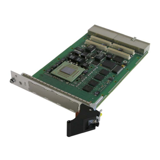
Page 34: Figure 6: Board Photo
Interfaces Chapter Scope This chapter describes the interfaces of the CM6 CompactPCI Single Board Computer located on the board and on the front panel. Each section on a particular interface includes a graphics illustration of the connector and a pin assignment table as well as notes on certain signal line characteristics, if necessary. -
Page 35: Figure 7: Cm6 Front Panel
Front Panel Interfaces Refer to figure 7 for front panel of the CM6 board. Figure 7: CM6 front panel CM6 Connectors This chapter describes connector pin assignments on the CM6. A pin assignment description for available transition module can be found in the corresponding appendix chapters. - Page 36 Signals separated by a slash Alternative signal assignments not connected Attention: Do not insert a CM6 board in a 3/6U 64-bit Backplane because this may damage electrical interfaces at the CM6. GE Intelligent Platforms – CM6 Hardware Reference Manual, Fourth Edition Page 35...
- Page 37 +12V +5 V These signals are not used on the CM6, but have a pull-up to VIO The VIO signals are either 5 V or 3.3 V, depending on backplane Reserved – Pin is reserved in the PICMG 2.0 specification. It is not used on the CM6 board GE Intelligent Platforms –...
-
Page 38: Figure 8: Mounting Of Secondary Thermal Interface On Pmc Module
Processor PMC Standard VITA 32-2003. The enhancements provide pins for a second device (IDSELB and REQB#/GNTB#) and support non-monarch processor PMC cards. The PCI signaling voltage V(I/O) at the PMC is fixed to 3.3 V but the CM6 PMC is tolerant to 5 V signaling, too. Secondary Thermal Interface On conduction-cooled versions of boards and mezzanines the PMC modules may be equipped with optional Secondary Thermal Interfaces. - Page 39 Weak 10kΩ pull-down (PDN) to GND and pull-up (PUP) to VIO. Not connected Reserved Reserved. Do not connect anything V(I/O) I/O Voltage, connected with +3.3 V -12 V/+ 12V Only available if connected at the CPCI backplane. GE Intelligent Platforms – CM6 Hardware Reference Manual, Fourth Edition Page 38...
- Page 40 Either PMCIO01…08 or GPIO 0...7 are connected to the rear and with FlashKill option PMCIO09 is replaced with flash kill signal (FKILL#). the table below shows the standard PMCIO – cPCI J2 configuration: GE Intelligent Platforms – CM6 Hardware Reference Manual, Fourth Edition Page 39...
- Page 41 PMCIO08* PMCIO09** PMCIO10 PMCIO11 PMCIO12 PMCIO13 PMCIO14 PMCIO15 PMCIO16 PMCIO17 PMCIO18 PMCIO19 PMCIO20 PMCIO21 PMCIO22 PMCIO23 PMCIO24 PMCIO25 PMCIO27 PMCIO28 PMCIO29 PMCIO30 PMCIO31 PMCIO32 PMCIO36 PMCIO38 PMCIO50 PMCIO52 GE Intelligent Platforms – CM6 Hardware Reference Manual, Fourth Edition Page 40...
- Page 42 **PMCIO09 will be replaced with flash kill signal (FKILL#) option. PMCIO Configuration: There is an option available which is optimized for the G2 Graphic PMC card from GE Intelligent Platforms. GE Intelligent Platforms – CM6 Hardware Reference Manual, Fourth Edition Page 41...
- Page 43 PMCIO08* PMCIO09** PMCIO10 PMCIO11 PMCIO12 PMCIO13 PMCIO14 PMCIO15 PMCIO16 PMCIO17 PMCIO18 PMCIO19 PMCIO20 PMCIO21 PMCIO22 PMCIO23 PMCIO24 PMCIO25 PMCIO26 PMCIO27 PMCIO28 PMCIO29 PMCIO31 PMCIO37 PMCIO39 PMCIO42 PMCIO44 PMCIO50 GE Intelligent Platforms – CM6 Hardware Reference Manual, Fourth Edition Page 42...
- Page 44 **PMCIO09 will replaced with flash kill option (FKILL#) Transition Module Please refer to the appendix chapters for interface location and connector pin- outs for the optional transition module CTM19 (Appendix A). GE Intelligent Platforms – CM6 Hardware Reference Manual, Fourth Edition Page 43...
- Page 45 GE Intelligent Platforms – CM6 Hardware Reference Manual, Fourth Edition Page 44...
- Page 46 PCI Express 64-bit address environment. Local Bus Controller The local bus controller (LBC) of the MPC8641 in the CM6 is used as a general-purpose machine which supports compatible SRAM, ROM and peripherals with 8-, 16-, 32-bit devices. The supplied chip selects of the LBC...
- Page 47 CPLD Registers One device connected at the LBC is the CPLD (U1949) which provides seven CM6 specific control and status registers. The CPLD register are connected to the Local Bus Controller at chip select LCS1 with 8-bit data width. The bit description is in little endian, least significant bit is at the right and most significant bit at the left end of the byte.
- Page 48 PLD is enabled output of 1 – SMI output is masked 1 – SMI output is PLD is and force SMI to inactive masked and force enabled SMI to inactive GE Intelligent Platforms – CM6 Hardware Reference Manual, Fourth Edition Page 47...
- Page 49 System clock selection bit 1 SEL1 SEL0 SYSCLK 166 MHz 66 MHz 100 MHz 133 MHz PMC_PCIXCAP 0 - PMC is in conventional PCI mode 1 – reserved GE Intelligent Platforms – CM6 Hardware Reference Manual, Fourth Edition Page 48...
- Page 50 8192ms 16384ms Reserved Always 0 WRST[2:0] WRST2 WRST1 WRST0 Time WRST[2:0] Watchdog 0 ms : 000 Reset time 256ms 512ms 1024ms 2048ms 4096ms 8192ms 16384ms Reserved Always 0 GE Intelligent Platforms – CM6 Hardware Reference Manual, Fourth Edition Page 49...
- Page 51 Boot Code. PLD Version Register (VER) Address: Base + Offset 7 Size: 8 bit Table 16: PLD Version Register (VER) Name Write Read Default PLD Version GE Intelligent Platforms – CM6 Hardware Reference Manual, Fourth Edition Page 50...
- Page 52 Reserved General Purpose I/O Port The CM6 uses the I/O Port of the PCI-PCIe Bridge Pericom Pi7C9X130 and Pericom Pi7C9X110 for the general purpose I/Os which are optional available at the rear. For programming see the manual of appropriate Pericom bridge...
- Page 53 PCIe channel two is one line wide and provides with the Pi7C9X110 bridge the 32bit/66MHz PCI bus for the cPCI compliant backplane. This bridge is a universal transparent/non-transparent bridge to support the CM6 as system slot controller or non-system (peripheral) slot controller function.
- Page 54 SMBus 2 SMBus two connects the CM6 board specific serial devices. Following devices and address scheme are used. Address: 1101 110x clock device ICS9FG104 1001 100x Thermo Sensor LM86 1010 01xx User EEPROM 128kByte 1010 00xx SPD and Factory EEPROM 256Bytes GE Intelligent Platforms –...
- Page 55 GE Intelligent Platforms – CM6 Hardware Reference Manual, Fourth Edition Page 54...
- Page 56 10/100/1000 Ethernet controllers. Clock Assignment The clock scheme of the CM6 is very flexible. The main clock is a generated from PLL and support 66MHz, 100MHz, 133MHz, and 166MHz for the MPC8641. With this main clock the MPC8641 determines with configuration pins the ratio between main clock –...
- Page 57 +12 V that means an output which drives FKILL# must withstand a high level of +12V. The feature is only usable if the CM6 is supplied with +12 V power rail. Besides the flash devices other logic may be damaged if a Flash Kill is performed! GE Intelligent Platforms –...
- Page 58 The CM6 uses both PCI Express Buses for connection of the cPCI and PMC PCI to PCIe bridges. The bus to the PMC bridge is x4 wide and connected to a PCI PCIe bridge (Pericom Pi7C9X130).
- Page 59 2, Unpacking and Handling. Watchdog For security of application software, the CM6 offers a software controlled hardware two stage watchdog with independent count values for each stage. First stage generates a SMI. The second stage issuing a reset signal if its time- out interval expires.
- Page 60 • Prioritized interrupt reporting • Overrun, parity, and framing error detection The COM1 Port at the CM6 has a RS232 compliant driver and the COM2 Port a RS422/485 compliant driver. The RS422/485 driver outputs can be controlled by a driver enable signal from the CPLD Control Register (CR) bit 0.
- Page 61 CTM19 is supplied with 3.3 V power. JTAG Interface The CM6 provides an IEEE 1149.1 (JTAG) Scan chain that can be used to check major components included in the chain for open and short circuits, and continuity. The JTAG Scan chain is driven at +3.3 V. The Boundary Scan chain for CM6 includes the following components: •...
- Page 62 Serial EEPROMs For storage of SPD and factory user data a serial EEPROM is implemented on the CM6 board. It is a standard 24C04 type EEPROM with 512 bytes. The user EEPROM is a 24C1024 type with 128 kByte. GE Intelligent Platforms – CM6 Hardware Reference Manual, Fourth Edition...
- Page 63 BFAIL# (cPCI J2 pin E19) is an open drain signal to source a LED at 3.3 V with 4 mA. The CM6 has an active low board fail signal (BFAIL#) at J2. The signal is active after reset and may set inactive after BIT test. The user may connect a red LED at the signal and if the LED is off this indicate a successful BIT test.
-
Page 64: Figure 9: Led
The reset source is monitored by the Reset Source Register (RSR) within the CPLD see section CPLD registers for description. The following table lists all possible sources of reset. GE Intelligent Platforms – CM6 Hardware Reference Manual, Fourth Edition Page 63... - Page 65 In non-system mode it is an input and holds the CM6 (as cPCI peripheral) in reset. GE Intelligent Platforms – CM6 Hardware Reference Manual, Fourth Edition Page 64...
- Page 66 480 g Voltage Requirements The CM6 requires +5 V and +3.3 V power. To avoid power sequencing problems the two power rails are controlled by MOSFET power switches. The internal power is switched on when the +5 V and +3.3 V reach the minimum voltage and the cPCI signal BDSEL# (cPCI-J1 pin D15) is low.
- Page 67 CM6. Power Consumption Table 26 is intended to help you calculate the power consumption of a CM6 system. For measurement, the CM6 board is mounted on a CPCI backplane. The values are typical measured.
- Page 68 Storage, Operating Up to 95 %, non-condensing Storage temperature for N-, 8-styles is between -55 °C (low) & +105 °C (high). Shock and vibration (see table 28) values for the CM6: Table 28: Shock and vibration conditions 1-, 2-, 3-, 4-Style...
-
Page 69: Figure 10: Heat Sink Diagram For Air Cooled Versions (1-,2-,3-,4-Style)
Gigabit links up and without a mounted PMC card • the maximal card edge is defined if CPU core temperature reaches 105°C • please see CM6 thermal report for more information GE Intelligent Platforms – CM6 Hardware Reference Manual, Fourth Edition Page 68... - Page 70 VCC3-0.5 V @ -2 mA sourcing VCC3 is the +3.3 V voltage from the backplane The GPIOs are default inputs after reset. On the CM6 board there are 10kΩ pull-ups to +3.3 V at all GPIOs. Note: On CM6 Version 1.x only signals GPIO4...7 are usable.
- Page 71 By itself the onboard logic ground (GND) and the front panel/chassis frame ground (FGND) are isolated on the CM6 with a layout distance of more than 0.3 mm in all PCB layers. Also standard racks (our starter cage, too) connect both grounds at the power supply for safety reasons.
-
Page 72: Figure 11: Placement Diagram Component Side
Placement Plan Component Side CM6 V1 Figure 11: Placement diagram component side GE Intelligent Platforms – CM6 Hardware Reference Manual, Fourth Edition Page 71... -
Page 73: Figure 12: Placement Diagram Solder Side
Placement Plan Solder Side CM6 V1 Figure 12: Placement diagram solder side GE Intelligent Platforms – CM6 Hardware Reference Manual, Fourth Edition Page 72... -
Page 74: Figure 13: Transition Module Ctm19
Appendix A Transition Module CTM19 The CTM19 transition module is used for easy connection of I/O signals to standard connectors. Figure 13: Transition Module CTM19 GE Intelligent Platforms – CM6 Hardware Reference Manual, Fourth Edition Page 73... -
Page 75: Figure 14: Layout Of Transition Module
This chapter describes all connector pin outs on the CTM19 transition module. Serial Interfaces COM1 (P2200, P2202) and COM2 (P2201) The CM6 offers two serial ports. COM1 is a RS232 compliant and COM2 has a RS422/RS485 interface. All COM ports are accessible via the transition module on 10-pin headers. -
Page 76: Figure 15: Com1 At Transition Module
+5 V fused +5 V supply via P1101 of the CTM19 and fused with a 2 A fuse. The installed fuse does automatically recover if the over current is resolved. GE Intelligent Platforms – CM6 Hardware Reference Manual, Fourth Edition Page 75... - Page 77 3.3 V supplied via P1102 and 4.7 kΩ resistor COPVCC3 3.3 V supplied via P1102 and 10 Ω resistor for current limitation COP_TCK CKSTOPIN# COP_TMS COP_SRST# COP_HRST# CHKSTOPOUT# GE Intelligent Platforms – CM6 Hardware Reference Manual, Fourth Edition Page 76...
-
Page 78: Figure 16: Ethernet Connectors
The LEDs at the RJ45 connectors are not connected and have no function. Table 38: Ethernet pin assignments (P5000 & P5500) Ethernet1 P5000 Name Ethernet2 P5500 LPx_DA+ (TxD+) LPx_DA- (TxD-) LPx_DB+ (RxD+) LPx_DC+ LPx_DC- LPx_DB- (RxD-) LPx_DD+ LPx_DD- FGND GE Intelligent Platforms – CM6 Hardware Reference Manual, Fourth Edition Page 77... - Page 79 If the Flash Kill jumper (J1902) is closed and the option is available at the CM6 this will destroy the flash devices. PMCIO connector P7101 P7101 a 64 pin header contains PMCIO signals: GE Intelligent Platforms – CM6 Hardware Reference Manual, Fourth Edition Page 78...
- Page 80 PMCIO22 PMCIO23 PMCIO24 PMCIO25 PMCIO26/52* PMCIO27 PMCIO28 PMCIO29 PMCIO30/37* PMCIO31 PMCI32/39 PMCIO36/42* PMCIO30/37* PMCIO38/44* PMCIO32/39* PMCIO36/42 PMCIO50 PMCIO26/52* HW_\CFG HW_\WP *: Alternative signal assignment depends from CM6 option. GE Intelligent Platforms – CM6 Hardware Reference Manual, Fourth Edition Page 79...
- Page 81 Reset Button The Reset button will issue a hard power-on reset. The reset signal PRST# is active for all subsystems of the CM6 and if the CM6 board is system board also for all peripheral boards at the cPCI system.
- Page 82 +3.3 V +5 V +5 V +5 V -12V +12V +5 V VIO is connected to +3.3V optionally 100 Ω pull-down if the CTM19 is used without backplane GE Intelligent Platforms – CM6 Hardware Reference Manual, Fourth Edition Page 81...
-
Page 83: Figure 18: Placement Plan Ctm19
Placement Plan CTM19 Figure 18: Placement plan CTM19 GE Intelligent Platforms – CM6 Hardware Reference Manual, Fourth Edition Page 82... - Page 84 Americas & Pacific Rim (Japan, Korea, China, Philippines, AUS, NZ) Technical Support If you should have a problem with a GE Intelligent Platforms product: Free technical support is available by phone, fax or email. Telephone support is available at main locations or at the regional center where the product was bought.
- Page 85 In case of difficulties provide at least the information listed below to an appropriate support center or on their web site as listed above. GE Intelligent Platforms – CM6 Hardware Reference Manual, Fourth Edition Page 84...
- Page 86 Contact: Name & Phone Number • Detailed Description of the Problem/Defect For PowerPC based computers include: • Bootload version • Operating system used • Version of the BSP (Board Support Package) GE Intelligent Platforms – CM6 Hardware Reference Manual, Fourth Edition Page 85...
- Page 87 © 2010 GE Intelligent Platforms Embedded GE Intelligent Platforms Additional Resources Systems, Inc. All rights reserved. Information Centers * indicates a trademark of GE Intelligent For more information, please visit Platforms, Inc. and/or its affiliates. All other the GE Intelligent Platforms Embedded Sys- Americas:...
- Page 88 Artisan Technology Group is your source for quality new and certified-used/pre-owned equipment SERVICE CENTER REPAIRS WE BUY USED EQUIPMENT • FAST SHIPPING AND DELIVERY Experienced engineers and technicians on staff Sell your excess, underutilized, and idle used equipment at our full-service, in-house repair center We also offer credit for buy-backs and trade-ins •...