
Related Manuals for GE IMP2B


Summary of Contents for GE IMP2B
- Page 1 Intelligent Platforms Hardware Reference Manual IMP2B 3U cPCI Single Board Computer Edition 5 Publication No. IMP2B-0HH/5...
- Page 2 Rev 4 Waste Electrical and Electronic Equipment (WEEE) Returns GE Intelligent Platforms Limited is registered with an approved Producer Compliance Scheme (PCS) and, subject to suitable contractual arrangements being in place, will ensure WEEE is processed in accordance with the requirements of the WEEE Directive.
- Page 3 Preface This manual contains hardware information for the IMP2B boards with PCB artwork revisions 4 and onwards. The information contained in this manual must be used in conjunction with the PowerPact3 Family Product Manual. LINK PowerPact3 Family Product Manual, publication number PP3-0HH.
-
Page 4: Table Of Contents
3.13 DMA Engines ....................................... 26 3.14 I C Interface ......................................26 3.14.1 Serial EEPROM ........................................ 26 3.14.2 Real-Time Clock ......................................26 3.14.3 Elapsed Time Indicator ....................................27 3.14.4 Temperature Sensing ....................................27 (continued overleaf) 4 IMP2B 3U cPCI Single Board Computer Publication No. IMP2B-0HH/5... - Page 5 4.1.1 System Controller Card (IMP2B-xxxxA) ..............................43 4.1.2 Peripheral Only Card (IMP2B-xxxxB) ..............................44 4.1.3 Limited Host, Full PMC User I/O Card (IMP2B-xxxxD) ........................45 4.1.4 System Controller Card – Alternative PMC I/O (IMP2B-xxxxE) ....................46 4.1.5 J2 Connector Signal Descriptions ................................47 4.1.6 PMC Rear I/O Tracking....................................
- Page 6 Table 3-26 Interrupt Combination ................................38 Table 3-27 JTAG Chains ....................................39 Table 3-28 LEDs ........................................ 40 Table 3-29 BIT Status LEDs ..................................41 Table 4-1 Connector Functionality ................................42 6 IMP2B 3U cPCI Single Board Computer Publication No. IMP2B-0HH/5...
- Page 7 Table A-4 Reliability (MTBF) ..................................50 Table A-5 Product Codes ....................................51 List of Figures Figure 1-1 View of IMP2B ....................................9 Figure 2-1 Link Positions (Top) ................................... 10 Figure 3-1 Block Diagram .................................... 16 Figure 3-2 RS422/485 Signal Definition ..............................24 Figure 3-3 LED Positions ....................................
-
Page 8: Overview
1 • Overview Available with the PowerPC MC7448 RISC CPU with integrated L2 cache, running at up to 1.4 GHz, the IMP2B is based around a Marvell Discovery V (MV64560) Integrated System Controller, which combines high performance system control with multiple communication peripherals including high speed serial and dual Ethernet ports, all on a single chip. -
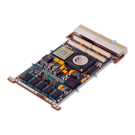
Page 9: Figure 1-1 View Of Imp2B
Figure 1-1 View of IMP2B Publication No. IMP2B-0HH/5 Overview 9... -
Page 10: Configuration
2 • Configuration The IMP2B is delivered with push-on jumpers, but for rugged or military applications, use optional zero Ohm resistors. This manual refers to link settings as “In” or “Out”. Meanings are as follows: In = jumper fitted - Out = jumper not fitted - Before changing any of the link options, refer to the appropriate section(s) in the following pages. -
Page 11: Suggested Link Settings
EPLD. With no jumpers fitted, the IMP2B boots from the default (Main) boot image; when a jumper is fitted on either of the links, the IMP2B boots from another boot image, as follows: Table 2-3 Links P2 1-2 and 3-4... -
Page 12: Backplane Flash Programming Link (P2 5-6)
2.5 Backplane Flash Programming Link (P2 5-6) This link holds the IMP2B’s processor in reset, allowing another processor card to program the IMP2B’s Flash across the CompactPCI backplane. This is for use during production programming only. Table 2-4 Link P2 5-6... -
Page 13: Boot Flash Write Enable Link (P3 3-4) And User Flash Write Enable Link (P3 5-6)
Boot and User areas of Flash. This emulates the type of protection previously implemented in hardware for users who are familiar with previous revisions of, or are using, existing software on the IMP2B. The state of these links is reflected in the EPLD... -
Page 14: Backplane Jtag Buffer Enable Link (P4 3-4)
In PICMG 2.0, Rev 3.0, it is recommended that the backplane JTAG signals are not used. When this link is out, the IMP2B does not drive these pins and so these signals may be used for any other purpose allocated to them. -
Page 15: Nvram/Serial Eeprom Write Enable Link (P5 3-4)
‘Limited Host, Full PMC User I/O’ Mode section. 2.14 Special Linking Requirements For ‘deployed-use’, any of the nine links on P3, P4 and P5 can be permanently made using zero Ohm, 0402 resistors. Consult the factory for individual requirements. Publication No. IMP2B-0HH/5 Configuration 15... -
Page 16: Functional Description
3 • Functional Description Figure 3-1 Block Diagram 3.1 PowerPC Processor The PowerPC processor used on the IMP2B is a Freescale MPC7448, clocked at up to 1.4 GHz. This is a 32-bit superscalar RISC processor with the following features: •... -
Page 17: Host Bridge
3.2 Host Bridge The Marvell MV64560 Discovery V Bridge provides the host, memory and PCI interface on the IMP2B. This device provides: Host bridge between the processor and the rest of the system • CompactPCI interface (PCI1) • • PCI-X interface to PMC site (PCI0) DDR2 SDRAM memory controller •... -
Page 18: Ram
CAUTIONS The second DDR2 RAM bank physically resides in the PMC ‘Keep-Out’ area. When the IMP2B is fitted with 1 GByte of DRAM memory, the available component height in the PMC ‘Keep-Out’ region for an install PMC is reduced from 10mm to 5mm. -
Page 19: Flash Memory
3.5 Flash Memory The IMP2B supports up to 256 MBytes of Flash memory, with 128 MBytes fitted as standard. This memory is implemented using Spansion S29GL512P Flash devices. These are configured as two banks of 16-bit wide devices, accessed via the MV64560 Device Bus. -
Page 20: User Flash
Sectors that are locked using the Persistent mode may not be unlocked using this mechanism. The IMP2B boot software uses the non-persistent protection method to lock the sectors in the Boot or User Flash areas depending on the state of the... -
Page 21: Memory Map Set Up By Vxworks (As Seen By Cpu)
Only PMC cards that operate using 3.3 Volt signaling (VIO) are supported. CAUTION Fitting a PMC designed to operate at 5 Volts VIO may cause damage to the IMP2B and/or PMC The PMC site supports Processor PMCs (as defined by VITA32-2002) operating in non-Monarch mode only. -
Page 22: Pmc Rear I/O Tracking
CAUTION If an IMP2B built in this mode is to be used in the Host slot of a commercial rack, take extra care, as some PMCs may have their I/O connected to backplane traces that they are not designed to drive (i.e. -
Page 23: Alternative Pmc I/O' Mode
J2-E17 3.7.4 ‘Alternative PMC I/O’ Mode The IMP2B supports a build of ‘Alternative PMC I/O’ mode as a build option. This allows four of the PMC I/O not normally available in Host mode to be made available. When this option is selected, PMC I/O [45:48] are replaced by PMC I/O [61:64]. -
Page 24: Serial Ports
The ports use a single Intersil IS41334 transceiver and are capable of operation up to 400 kBaud in RS232 mode and up to 10 MBaud in RS422 mode (reducing to 8 MBaud over temperature). Both ports are available as rear I/O from the connector. 24 IMP2B 3U cPCI Single Board Computer Publication No. IMP2B-0HH/5... -
Page 25: Ethernet
133 MHz and has a resolution of 7.5 ns. It is disabled by default following reset. Two thresholds may be set. The first generates an interrupt to the processor and the second causes a hard reset to the local processor. Publication No. IMP2B-0HH/5 Functional Description 25... -
Page 26: Dma Engines
It has leap year compensation up to 2100 and it also features an alarm capability. Battery back-up is not supported. For more details see the device data sheet. LINK http://www.semiconductors.philips.com/cgi-bin/pldb/pip/PCF8563T/F4.html 26 IMP2B 3U cPCI Single Board Computer Publication No. IMP2B-0HH/5... -
Page 27: Elapsed Time Indicator
3.14.4 Temperature Sensing The IMP2B has two temperature sensors. An LM92 is used to measure the ambient board temperature and an ADT7461 is used to measure the CPU junction temperature. Both are capable of generating interrupts on either high or low ranges. -
Page 28: Epld
0x00000402 GPIO Data Register 0x00000404 GPIO Polarity Control Register 0x00000406 GPIO Interrupt Mode Register 0x00000408 GPIO Interrupt Active Register 0x0000040A GPIO Interrupt Enable Register 0x0000040C GPIO Masked Interrupt Status Register 28 IMP2B 3U cPCI Single Board Computer Publication No. IMP2B-0HH/5... -
Page 29: Board Id Register 1 - Offset 0X00000000
7 to 0 Read only Board major revision 0x02=2BB 15 to 8 Read only Board identifier (0x4A) 0x4A = IMP2B 3.15.3 Board ID Register 2 – Offset 0x00000002 Table 3-11 Board ID Register 2 Bits Mode Description Notes 7 to 0... -
Page 30: Device/Bus Information Register 2 - Offset 0X00000006
Reset was backplane 1 = Last reset was backplane (cPCI Reset) 0 = Last reset not software Read Only Reset was software 1 = Last reset was software (offset 0x40) 30 IMP2B 3U cPCI Single Board Computer Publication No. IMP2B-0HH/5... -
Page 31: Configuration Register 2 - Offset 0X0000000A
1 = PMC User I/O 1 to 64 configured 15 to 6 Reserved Software can use bit 5 to detect whether the IMP2B is built for System Controller or ‘Peripheral only’/‘Limited Host, Full PMC User I/O’ mode. 3.15.8 Control Register 1 – Offset 0x0000000C... -
Page 32: Control Register 2 - Offset 0X0000000E
Description Notes Scratchpad 1 0x0000001C 15 to 0 Read/Write Upper 16 bits Reset Value = 0x0000 Scratchpad 2 0x0000001E 15 to 0 Read/Write Lower 16 bits Reset Value = 0x0000 32 IMP2B 3U cPCI Single Board Computer Publication No. IMP2B-0HH/5... -
Page 33: Epld Interrupt Register - Offset 0X00000020
3.15.13 Software Reset Register – Offset 0x00000040 Table 3-21 Software Reset Register Bits Mode Description Notes Write 0x467A to generate a reset; writing any other value will have no 15 to 0 Read/Write Software reset effect. Power-up value = 0x0 Publication No. IMP2B-0HH/5 Functional Description 33... -
Page 34: Semaphore Register - Offset 0X00000060
GPIO[0] low = Fast Start (BIT skipped if Fast Start enabled) or Fast BIT selected. GPIO[0] high (default) = Full BIT selected. Fast Start is enabled by bit 7 of Configuration Register Where GPIO[0] is not available, Fast Start/Fast BIT is not supported. 34 IMP2B 3U cPCI Single Board Computer Publication No. IMP2B-0HH/5... -
Page 35: Gpio Direction Control Register - Offset 0X00000400
1 = Active low 3.16.4 GPIO Interrupt Mode Register – Offset 0x00000406 The bits indicate the interrupt mode of the corresponding GPIO line, as follows: 0 = Edge triggered (rising) 1 = Level triggered [default] Publication No. IMP2B-0HH/5 Functional Description 35... -
Page 36: Gpio Interrupt Active Register - Offset 0X00000408
1. The default is ‘Round-Robin’. The arbiter implements broken master detection (grant removed if bus is not used within 16 cycles of grant asserted) and bus parking on the last master. 36 IMP2B 3U cPCI Single Board Computer Publication No. IMP2B-0HH/5... -
Page 37: Resets
Hard reset all devices if Peripheral card Software Generated reset Hard reset all devices If the IMP2B is configured as the System Controller (Rack Host), then a hard reset causes the CompactPCI backplane reset to be driven active, resetting all peripheral cards in the system. -
Page 38: Interrupts
3.19 Interrupts The IMP2B uses the interrupt controller provided in the MV64560. The interrupt sources are fed into the multi-purpose pins and routed internally to the CPU interrupt output. Table 3-25 Interrupt Mapping Interrupt Source MV64560 MPP Pin Notes cPCI INTA... -
Page 39: Jtag
In PICMG 2.0, Rev 3.0, it is recommended that the Backplane JTAG signals are not used. When no jumper is fitted across link 3-4, the IMP2B does not drive these pins and so these signals may be used for any other purpose allocated to them. -
Page 40: Leds
Green BIT Passed DS267 On-card PSU power-up reset DS268 5 V/3.3 V power-up reset DS600 Hard reset The following diagram shows the positions of the LEDs. Figure 3-3 LED Positions 40 IMP2B 3U cPCI Single Board Computer Publication No. IMP2B-0HH/5... -
Page 41: Front Panel
BIT not run (Reset state) or BIT Failed Unlit Unlit BIT complete and passed If BIT fails, then DS264 and DS265 are illuminated to provide debug information. 3.22 Front Panel Figure 3-4 Front Panel Publication No. IMP2B-0HH/5 Functional Description 41... -
Page 42: Connectors
4 • Connectors The following table shows the function of the connectors on the IMP2B: Table 4-1 Connector Functionality Connector Function CompactPCI bus (see general description) CompactPCI bus, system and I/O J11, J12, J13, J14 PMC1 site (see general description) -
Page 43: J2 Connector Pinout
USB2.0 Port 2 CAUTION If an IMP2B is configured for Gigabit Ethernet and is connected to another Gigabit Ethernet capable device, the CPCI3UX605 (if used) must be configured to allow the port to be fully connected. Failure to do so will prevent the Ethernet port from functioning correctly. -
Page 44: Peripheral Only Card (Imp2B-Xxxxb)
USB2.0 Port 2 CAUTION If an IMP2B is configured for Gigabit Ethernet and is connected to another Gigabit Ethernet capable device, the CPCI3UX605 (if used) must be configured to allow the port to be fully connected. Failure to do so will prevent the Ethernet port from functioning correctly. -
Page 45: Limited Host, Full Pmc User I/O Card (Imp2B-Xxxxd)
Ethernet port from functioning correctly. CAUTION When using an IMP2B built in this mode in the Host slot of a commercial rack, take extra care, as some PMCs may have their I/O connected to backplane traces that they are not designed to drive (i.e. -
Page 46: System Controller Card - Alternative Pmc I/O (Imp2B-Xxxxe)
USB2.0 Port 2 CAUTION If an IMP2B is configured for Gigabit Ethernet and is connected to another Gigabit Ethernet capable device, the CPCI3UX605 (if used) must be configured to allow the port to be fully connected. Failure to do so will prevent the Ethernet port from functioning correctly. -
Page 47: J2 Connector Signal Descriptions
PMC User I/O’ modes) are not mapped according to the conventional PMC Pn4 to cPCI J2 scheme. The routing pattern used by the IMP2B is biased towards PMC cards that use the Pn4 connector pins in pairs (1-3, 2-4, 5-7, 6-8, etc.) The signals are tracked as 50 Ω... -
Page 48: A • Specifications
Table A-1 Technical Specification Features Details Comments System or Support for up to 7 peripheral slots (four IMP2B detects a backplane signal to configure in System Slot or Peripheral Slot Peripheral slot at 66 MHz) mode PowerPC Processor Freescale MC7448 Clocked at up to 1.4 GHz... -
Page 49: Electrical Specification
-12 V -11.4 -12.6 The IMP2B does not use the ±12 V supply lines, but they are fed to the PMC site. A.2.2 Power Consumption The IMP2B uses both +3.3 V and +5 V supply rails. Power dissipations are shown for an IMP2B with a 7448 and 1 GByte of RAM (no PMC fitted) operating at the stated frequencies. -
Page 50: Weight
A.3 Weight The weight of the IMP2B (level 4/5) is approximately 280 g. A.4 Reliability (MTBF) The following table shows the predicted values for reliability as Mean Time Between Failures (MTBF) and failures per million hours (fpmh). Table A-4 Reliability (MTBF) -
Page 51: Product Codes
9 = Level 9 (-55 °C to +85 °C – consult factory before ordering) NOTE Not all options or combinations of options are available. Please consult your local GE Intelligent Platforms sales office for full ordering information. A.6 Software Support... -
Page 52: Development Tools
I/O signals routed to the J2 connector may be accessed using a backplane module (CPCI3UX605) and breakout panels providing standard interface connectors. The CPCI3UX605 is an I/O card for use with the IMP2B. It plugs onto the rear of the CompactPCI backplane P2 connector and brings out the following groups of signals: COM1/COM2 RS232 •... -
Page 53: Index
Write Enable ............15 Rear Ethernet ............25 Elapsed Time Indicator ..........27 Limited Host, Full PMC User I/O Mode ....22 Electrical Specification ..........49 Links ........... See Configuration EPLD ................28 Ethernet ................. 25 Publication No. IMP2B-0HH/5 Index 53... - Page 54 Voltage Supply Requirements ........49 Device/Bus Information 1 ........29 VxWorks Memory Map ..........21 Device/Bus Information 2 ........30 EPLD Interrupt ............33 Watchdog Timer ............25 Weight ................50 54 IMP2B 3U cPCI Single Board Computer Publication No. IMP2B-0HH/5...
- Page 55 Confidential Information - This document 1 800 322 3616 or 1 256 880 0444 contains Confidential/Proprietary Information Asia Pacific: of GE Intelligent Platforms, Inc. and/or its defense.ge-ip.com suppliers or vendors. Distribution or 86 10 6561 1561 reproduction prohibited without permission.