ABB RMC-100 User Manual
Remote modular controller
Hide thumbs
Also See for RMC-100:
- Startup manual (37 pages) ,
- Quick start manual (2 pages) ,
- Startup manual (40 pages)

Related Manuals for ABB RMC-100


Summary of Contents for ABB RMC-100
- Page 1 — A BB MEA SU RE ME NT & A NA LYTI CS | 2 1 055 5 2 MNA E Remote Modular Controller User Manual RMC-100 Measurement made easy...
-
Page 2: Table Of Contents
Waste Electrical and Electronic Equipment (WEEE)..............8 Safety ..........................8 Potential safety hazards ....................9 1 System description ..................... 10 Features overview ....................10 2 Physical Description ....................11 RMC-100 housing ....................11 2.1.1 LCD display ..................... 13 2.1.2 Enclosures ....................14 Electronic board ....................15 2.2.1... - Page 3 Procedure to configure 2-Networks mode ............64 Expand serial communication capacity ..............67 4.8.1 Expand with ABB’s XIO ................67 4.8.2 Expand with third-party Ethernet-serial devices ..........67 21 05 55 2MN A E | RM C-1 00 | 3...
- Page 4 Digital input and output configuration............68 4.9.5 Pulse input configuration ................69 4.9.6 Expand I/O capacity with the ABB XIO ............70 4.10 Configure directly attached TFIO interfaces ..............70 5 Advanced setup ......................73 Configure the LCD backlight ..................73 Configure low power use..................
- Page 5 8.4.1 When to upgrade ..................180 8.4.2 Software update packages for the RMC............181 8.4.3 Download software from the ABB website ........... 181 8.4.4 Determine device software part number/version .......... 183 8.4.5 Load the update software package ............. 185 System restart ....................188 8.5.1...
-
Page 6: List Of Tables
Table 1-1: General specifications ..................10 Table 2-1: LCD display characteristics ..................13 Table 2-2: Xcore enclosures available ..................14 Table 2-3: RMC-100 electronic board specifications ..............15 Table 2-4: Memory components .................... 16 Table 2-5: Ethernet ports ....................18 Table 2-6: Analog input specifications .................. -
Page 7: Additional Information
RMC-100 Startup guide 2105551 Wiring diagrams RMC Generic pinout User Drawing 2105617 RMC-100 AI to ABB 2600 T pressure transmitter User Drawing 2105593 RMC-100 COMM (RS-485) to ABB XMV (267/269CS/266J) W/RTD User 2105579 Drawing RMC-100 to ABB FCB Coriolis meter User Drawing... -
Page 8: Compliance
— Compliance Cyber security This product is designed to be connected, and communicate information and data, via a network interface. All ABB products should be connected to a secure network. It is the customer's sole responsibility to provide, and continuously... -
Page 9: Potential Safety Hazards
WARNING: According to ISO 9996, use only sufficiently insulated tools for the electrical connection. Also consider the following regulations: – The applicable standards and safety regulations concerning the construction and operation of electrical installations – The regulation on technical working materials (safety guidelines for tools) –... -
Page 10: System Description
System description The Remote Modular Controller (RMC-100) provides measurement, automation, monitoring, alarming, asset data management, control, and data logging applications. A single RMC-100 controller can manage automation, liquids and gas measurement, and asset data concentration for very large production and transmission facilities. -
Page 11: Physical Description
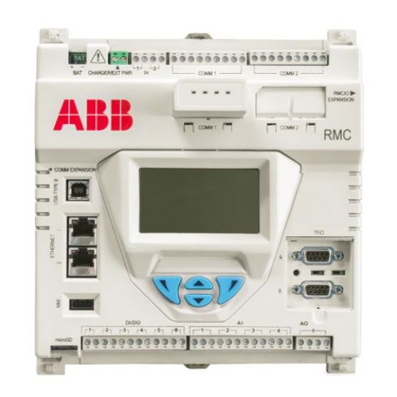
A DIN rail mountable plastic housing packages the RMC electronic board and its components. IMPORTANT NOTE: The RMC must be installed on an interior wall, or in an enclosure that meets the environmental ratings for the location. See section 2.1.2 for information about ABB enclosures. See section 3.1.1 for information about third-party enclosures. - Page 12 Figure 2-1: RMC-100 housing cover exterior Legend for Figure 2-1: RMC-100 housing cover exterior Description Description Battery connection (BAT) Reset button Charger input when battery-powered, or Security switch external power supply when not battery- powered (CHARGER/EXT PWR) Pulse input (Pulse Input, PI)
-
Page 13: Lcd Display
Figure 2-2 identifies the exterior of the housing base. Figure 2-2: RMC-100 housing base exterior Legend for Figure 2-2: RMC-100 housing base exterior Description Description Housing slot (secures top cover) Horizontal DIN rail slot... -
Page 14: Enclosures
The directional buttons do not allow any data entry. 2.1.2 Enclosures The RMC can be purchased already installed in an enclosure. ABB offers the Xcore enclosures described in Table 2-2. For more information and complete specifications see www.abb.com/upstream. -
Page 15: Electronic Board
DANGER – Serious damage to health / risk to life. Explosion Hazard: Do not connect or disconnect connectors or their terminations while energized unless the area is known to be non-hazardous. Table 2-3: RMC-100 electronic board specifications Component Description Core processor... -
Page 16: Processor And Memory
Component Description Flash. Factory-supplied registry (MAC address) is stored in 256-byte E2PROM LCD interface Parallel 128 x 64 graphic LCD with backlight Directional button Dedicated 4 button interface: up, down, left, and right interface Communication ports 2 software-configurable RS-232/RS-485/RS-422 hot-swappable serial ports with 2 communication modules 1 USB 2.0 device interface 3-port 10/100 Mbps Ethernet switch: 2 external ports available for... - Page 17 Baud Rate: 2,400 to Local serial communication (RS- 115,200 bps 232) Available only on external (Manually configurable weatherproof circular military- from the user interface) type connector on ABB Xcore enclosures (MMI-to-military cable required: Part number 2101412- 001) 4, 5 ETHERNET 1, RJ-45 100 Mbps or 10 Mbps full –...
-
Page 18: Table 2-5: Ethernet Ports
Port name Connector Data transfer rate Use (connections) type (port speed) COMM Proprietary (Future use) For future serial communication EXPANSION modules to expand serial port capacity 2.2.2.1 Serial communication ports The COMM 1 and COMM 2 slots each contain a 40-pin connector to support a hot-swappable serial communication module (Figure 2-7). -
Page 19: Inputs/Outputs
Communication between these two networks requires an external router. Each Ethernet interface must have its own IP parameter configuration. Ethernet mode selection depends on field configurations, cybersecurity requirements, type of ABB devices connecting to the RMC, and available network equipment. The 1 Network mode can simplify device management and IP configuration. -
Page 20: Table 2-6: Analog Input Specifications
Figure 2-8: Inputs and outputs Legend for Figure 2-8: Inputs and outputs Port name Terminal type Removable terminal connector (4 POS), screw termination. Wire gauge 12 AWG to 22 AWG. Removable terminal connector (4 POS), screw termination. Wire gauge 12 AWG to 22 AWG. -
Page 21: Table 2-7: Analog Output Specifications
Electrical specification Description Value (each point) converter, ADC) resolution for the input Each AI input has TVS protection, typical V threshold AI input protection Vtvs 32 Vdc typical level to begin conducting. 2.2.3.2 Analog output The RMC provides a single (1) analog output. The AO has a voltage-sourcing diode input voltage pin, a current sinking pin, a current sourcing pin, and a ground pin. -
Page 22: Tfio Expansion Interfaces
TFIO B. Each TFIO interface supports up to 22 TFIO modules (44 total). The RMC uses two independent buses to communicate with the modules. ABB Totalflow devices have an I/O protocol to exchange information with the modules. The buses operate in a master/slave mode, with the main device board acting as master. -
Page 23: Power Ports
Figure 2-9: TFIO module 2.2.5 Power ports The RMC has two ports supporting two power connection options or modes. Select one of the following modes: – Battery mode: a 12 volt Seal Lead Acid (SLA) battery with a charger supplies power. –... -
Page 24: Table 2-11: Power Source Requirements Per Mode
Figure 2-12: External power mode External Power Supply CHARGER/EXT PWR IMPORTANT NOTE: If you do not use ABB-approved power sources, verify that customer- supplied power sources meet these requirements. For additional details about requirements, see section 3.1 Site planning and requirements. -
Page 25: Security Switch
Table 2-12 Table 2-13 provide the battery port (BAT) and CHARGER/EXT PWR port specifications. Table 2-12: Battery port specifications Electrical specification Description Value or range Battery voltage Valid battery voltages for SLA 9.0 - 15.5 Vdc Charging battery current range Maximum charge current 0.05 - 1.65 A Maximum battery capacity... -
Page 26: Super Capacitor
2.2.9 Super capacitor The RMC design includes an onboard super capacitor (Super CAP) that serves as a short-term power reservoir. In the event of a loss of power or a reset, the charged capacitor prevents the supply voltage from falling to zero for 2.5 seconds. This delay allows the system time to save data, such as trending files, and restart configuration. -
Page 27: Table 2-14: Applications Available With Rmc
Click Application/License Management>Credit/App Info. Click Help for additional information. Table 2-14: Applications available with RMC Application System applications System Display XSeries (LCD display) Measurement Tube applications AGA-3 Measurement Gas Orifice SU AGA-7 Measurement Gas Turbine SU V-Cone Measurement V-Cone SU Coriolis SU API Liquid SU Nozzle SU... -
Page 28: Configuration Files
The RMC contains the following configuration files: – Factory configuration is the ABB default factory configuration, or a customer-specific configuration programmed into the factory folder during final assembly. The factory configuration is read-only and stored in persistent memory. It can only be updated at the factory. -
Page 29: Customer Data Collection Files
SSH provides an encrypted communication channel, which requires private key authentication for access to the controller. Secure access is available for troubleshooting purposes only and is reserved for advanced users and ABB technical support or development personnel. See section... -
Page 30: Enclosure Requirements
The RMC must be installed in an enclosure that complies with the following specifications: – The enclosure protects the RMC-100 against shock and impact. – For Class I, Division 2, or other outdoor installations, the RMC is installed in an enclosure rated at least Type 3R, according to the environment. -
Page 31: Unpack And Inspect
– Inspect each item for damage: RMC exterior, LCD display, optional equipment if purchased. If there are any missing, incorrect, damaged parts or noticeable defects, call the ABB main office number on the last page of this manual. Basic hardware installation This is an overview of a typical hardware installation. -
Page 32: Standalone Mounting
3-2). Mount the enclosure per field specifications. The RMC is usually already mounted on an internal DIN rail inside the enclosure. To use non-ABB enclosures, follow the vendor’s mounting instructions. Figure 3-2: Xcore enclosure top mounting tags and interior view... -
Page 33: Wire Serial Communication Ports
3.5.4 Wire serial communication ports Wire the RMC serial communication (serial communication, COMM) ports to communicate with and power external devices. The type of serial interface the external device requires determines the wiring for communication. Wire for power if there is no external supply powering the external device. This section provides wire length specifications per serial interface type, port pinouts and generic instructions for field wiring. - Page 34 Figure 3-3: COMM terminals and modules 3.5.4.1 Wire remote communications equipment (radio) The controller serial communication (COMM) ports can be wired with remote communication equipment, such as a radio. Figure 3-4 shows the connection between radio equipment and one of the COMM ports.
-
Page 35: Wire Input And Output
Figure 3-5: COMM 1 for RS-485 communication with multiple devices RS-485 RS-485 Power + Power + Ground - Ground - Multivariable Multivariable transmitter transmitter 3.5.5 Wire input and output Wire the RMC I/O ports to monitor, control and power external devices. Wire for power if the external device has no external power supply. -
Page 36: Table 3-3: Analog Input Pinouts
Table 3-3: Analog input pinouts Input Description Input Description PWR-power PWR-power A1-input signal A3-input signal GND-input ground GND-input ground PWR-power PWR-power A2-input signal A4-input signal GND-input ground GND-input ground Figure 3-6: Analog input pinouts 3.5.5.2 Analog output pinouts Table 3-4 Figure 3-7 identify the AO pinouts. -
Page 37: Connect Expansion Modules
Figure 3-8: Pulse input pinouts 3.5.5.4 Digital input and output pinouts Table 3-6 Figure 3-9 identify the DI/DO pinouts. Table 3-6: Digital I/O pinouts DI/DO Description DI/DO Description SIG-Signal DI/DO 1 SIG-Signal DI/DO 4 GND-ground GND-ground SIG-Signal DI/DO 2 SIG-Signal DI/DO 5 GND-ground GND-ground SIG-Signal DI/DO 3... - Page 38 RMC 2 Host System With PCCU Ethernet 1 Ethernet 2 RMC 3 Ethernet 1 Figure 3-11 illustrates how an Ethernet port supports connecting other ABB equipment. 3 8 | R MC-1 00 | 2 10 55 5 2MN A E...
-
Page 39: Connect Tfio Modules
Figure 3-11: Connect RMC to other ABB devices TCP/IP network Ethernet 1 Ethernet 2 Host system Host with System PCCU 10/100 BaseT Ethernet switch or hub Other ABB devices such as XFC, XRC, and NGC Never connect Ethernet 1 and Ethernet 2 to the same Ethernet switch (Figure 3-12). -
Page 40: Table 3-7: Tfio Modules
NOTICE – Equipment damage. When the TFIO interface is disabled, the modules remain powered. Remove the power from the RMC before connecting or disconnecting additional TFIO modules or the TFIO cable. Failure to power down the RMC can result in damage to the module. -
Page 41: Connect Third-Party Serial Modules
The RMC power-on sequence initiates when power is connected. The LCD displays the following information as the controller completes its startup: – ABB TOTALFLOW RMC-100 identifies the controller name and model – BOOT 2105412-XXX indicates the version of the boot software –... -
Page 42: Power With Battery And Charger
The hardware required for a battery installation is: – One 12 volt SLA battery – One battery cable (included with ABB-approved batteries) Before installation, inspect the battery cable and connectors for breakage where they terminate on the battery. To install and connect the battery: Install and secure the battery at the appropriate location. - Page 43 Remove the CHARGER/EXT PWR terminal connector to wire the charger cable before connecting the charger to the board. IMPORTANT NOTE: Call the ABB main office number on the last page of this manual for information about mounting the solar panel on the top or side of a building.
-
Page 44: Power With External Power Source
Continue with the installation if the measured output voltage is within the manufacturer’s specification, per the specification sheet supplied with the panel. Call the ABB main office number on the last page of the manual if the measured voltage is out of specification. -
Page 45: Enable Lithium Battery Backup
Figure 3-16: Connect the external power supply External Power Supply CHARGER/EXT PWR Apply power to the external power supply. Observe the power-on sequence information scrolling on the LCD to verify that the RMC is receiving power. See details in section 3.7.1. When the DATE/TIME displays, the sequence is complete. -
Page 46: Startup
RMC. PCCU32 software operates in a Windows® environment. To install with a PCCU32 installation file downloaded from the ABB website: Locate the downloaded file on the PC or laptop. The file downloaded is compressed. Un-compress the downloaded file. - Page 47 Figure 4-1: USB port for local operator access Laptop Type A Port Type B Port USB Cable To set up communication using the USB port: Power on the RMC and the laptop or PC. Connect the USB cable. An annunciator in the LCD displays a lower case "u" for local USB connection.
-
Page 48: Using The Ethernet Ports
Table 4-2 displays the cabling specifications for Ethernet ports. Table 4-2: Ethernet cabling Supported device Required cabling termination ABB part (connectors) or adaptors number (with Ethernet 10/100 BaseT ports) Host system (operator laptop or computer) 1681011 Straight-through Ethernet CAT 5... - Page 49 IP address. Use the default RMC IP address as the target address for connection setup using PCCU. Figure 4-5: First-time local connection with RMC-100 using Ethernet (2-port switch mode) 21 05 55 2MN A E | RM C-1 00 | 4 9...
- Page 50 IMPORTANT NOTE: If the device is configured for network communication (connected to the corporate network or the field network), a valid IP configuration for the field network must replace the factory IP configuration default. Local access to devices on a network is still supported after the default configuration is replaced, but the operator laptop must have an IP configuration compatible with the non-default addresses assigned to the devices.
- Page 51 Figure 4-7: IP for host system 4.2.2.3 Set up PCCU32 and connect To configure PCCU32 for TCP/IP communication: Power on the RMC and the laptop or PC. Connect the Ethernet cable. Launch PCCU. Click Setup on the PCCU32 toolbar menu. The System Setup window displays. Click TCP/IP.
-
Page 52: Using The Mmi Port (When Using Enclosures)
Ethernet port for direct connection if the RMC has been installed standalone. Use the USB port and a RS-232-to-USB adapter for laptops without legacy DB-9 RS-232 ports. ABB recommends and sells the Digi® Edgeport®/1 converter (part number 1801382-001). Contact technical support to order or for more details. -
Page 53: Change The Lcd Display
Figure 4-9: Station Setup screen Change any other settings in the Station Setup tab as necessary. Leave PCCU open to the Station Setup tab. IMPORTANT NOTE: Additional fields in WinCCU uniquely identify the meter, including fields for the lease holder, producer, operator, and buyer. Edit these fields on the host computer in the ID manager, not on the RMC. - Page 54 Click a port (COM1 or COM2). Select the appropriate application from the Select Application drop-down list. IMPORTANT NOTE: The applications are for specific products. If the external device is not an ABB product, select Generic Com App. Select the appropriate protocol from the Select Protocol drop-down list.
- Page 55 (TXD) and received by (RXD) the RMC. The PWR LED light is on if the RMC is powered on. Figure 4-13 provides a communication configuration example to connect an ABB Totalflow product, such as a multivariable transmitter or XMV. The XMV interface application supports this type of connection.
-
Page 56: Enable Serial Port Switched Output Power
Figure 4-14: Serial port configuration for remote communication 4.4.2 Enable serial port switched output power When powering external devices from the communication ports, use switched power to supply voltage to those devices only when needed. Wire the external devices to the Sw VOUT pins to support this feature. -
Page 57: Network Modes
IMPORTANT NOTE: Plan Ethernet connections carefully to protect your device and peripherals from unauthorized or malicious access. The device should only connect to a firewall-protected private network, never directly to the Internet. For security guidelines and recommendations, see section 6 Configure security (recommended). -
Page 58: Configure The Rmc For 1 Network Mode (2-Port Switch)
IMPORTANT NOTE: The RMC default Ethernet mode is 1 Network (2-port switch mode). The Ethernet ports are disabled by default. IMPORTANT NOTE: If you are connected to one of the Ethernet ports to configure the RMC-100, changing the Ethernet configuration and restarting the interface will cause you to lose connection. -
Page 59: Local Access To Rmc By Host (Connections)
Figure 4-17: Remote access by host to an RMC-100 in 2-port switch mode 4.6.2 Local access to RMC by host (connections) Figure 4-18 shows local access with an RMC that has been configured for connection to the customer wide area network. Local access to the RMC using Ethernet does not require disconnecting the RMC from the network. -
Page 60: Daisy-Chain Connection Support For Other Devices
Figure 4-18: Local access to an RMC-100 with non-default IP address 4.6.3 Daisy-chain connection support for other devices The RMC in 1 Network (2-port switch) mode supports daisy-chain connections with other devices. Additional devices in the field can connect to a local network switch (star topology) or to the RMC for the uplink to the wide area customer network (daisy-chain topology). -
Page 61: Procedure To Configure 1 Network Mode
Figure 4-19: RMC-100 daisy-chain connection support for additional devices (example: XIOs) Legend for Figure 4-19: RMC-100 daisy-chain connection support for additional devices (example: XIOs) XIO (4-port switch mode) RMC: 1 Network Mode (2-port switch) XIO (4-port switch mode) Customer wide area network (WAN) -
Page 62: Configure The Rmc For 2 Network Mode
10. Ping the device from the WAN or field network. The RMC should reply to the ping from the network. 11. If connecting another device to the RMC-100 in daisy chain fashion, configure the device with a unique IP address in the same subnet as the IP address configured on the RMC. -
Page 63: Remote Access To Rmc By Host (Logical Diagram)
Establish a remote connection to the RMC using the IP address assigned to the Ethernet port used for the corporate network uplink (in this example, E1). Additional ABB devices (in this example, XIO 1 and XIO 2) are daisy-chained to the RMC through port E2. The host cannot access those devices since the RMC isolates these devices from the WAN. -
Page 64: Procedure To Configure 2-Networks Mode
Figure 4-23: Local access to RMC and daisy chained devices Legend for Figure 4-23: Local access to RMC and daisy chained devices Customer Wide Area Network (WAN) RMC (2 Networks mode): E1-LAN RMC (2 Networks mode): E2-LAN Operator laptop 4.7.3 Procedure to configure 2-Networks mode Figure 4-24 shows an RMC supporting daisy-chain connection to a couple of XIOs. - Page 65 Figure 4-24: RMC daisy-chain connection support (2-Networks mode) Legend for Figure 4-24: RMC daisy-chain connection support (2-Networks mode) XIO (4-port switch mode) Customer Wide Area Network (WAN) XIO (4-port switch mode) RMC-E1 (LAN E1) RMC (2 Network Mode) RMC-E2 (LAN E2) To configure the RMC for 2 Network mode: Connect the Ethernet cable from the RMC to the network communication equipment (hub, switch, router, etc.).
- Page 66 10. Ping the device from the WAN or field network. The RMC should reply to the ping from the network. 11. If connecting another device to the RMC-100 in daisy chain fashion, configure the device with a unique IP address in the same subnet as the IP address configured on the RMC.
-
Page 67: Expand Serial Communication Capacity
ABB’s XIOs. The configuration of the device requires the vendor’s user interface which is separate from ABB’s PCCU. In addition to Ethernet-Serial conversion, the XIO also provides full controller capabilities, which third-party converters may not support. -
Page 68: Analog Input Configuration
Figure 4-27: PCCU32 Expert view 4.9.2 Analog input configuration To configure the analog input: Click I/O System on the navigation tree. The Analog Inputs tab displays (Figure 4-28). Figure 4-28: Analog input configuration Click the Signal field and select 0-30 Volt or 4-20 mA from the drop-down list. Click Send. -
Page 69: Pulse Input Configuration
Figure 4-30: Digital input and output configuration Select the Type from the drop-down list (Digital Input is the default). Configure each Digital I/O: Digital input mode: select the low and high threshold voltage. • Digital output mode: select the current value and the initial value. •... -
Page 70: Configure Directly Attached Tfio Interfaces
4.9.6 Expand I/O capacity with the ABB XIO The RMC supports I/O expansion through ABB’s Extensible IO devices (XIO). The RMC can poll and write from/to peripherals connected to TFIO Modules installed on the XIO. The RMC’s XIO Interface application is designed to handle communication transparently with the TFIO modules as if the modules were directly connected to the RMC. - Page 71 If modules were installed in TFIO-A, select TFIO-A Modules on the navigation tree. The TFIO Module Setup tab displays (Figure 4-33). Figure 4-33: TFIO-A Modules Setup Click the TFIO Module List tab (Figure 4-34): Verify all TFIO modules are connected and their type listed. Figure 4-34: TFIO-A Module List If modules were installed in TFIO-B, select TFIO-B Modules on the navigation tree.
- Page 72 Figure 4-35: TFIO-B Bus Enable tab (bus disabled by default) Select the TFIO-B Bus field to change to Enabled. Click Send. The TFIO Bus Enabled screen clears and the navigation tree refreshes. Select TFIO-B Modules from the navigation tree. The TFIO Module Setup tab displays (Figure 4-36).
-
Page 73: Advanced Setup
Figure 4-37: TFIO-B Module List 10. For specific module setup, expand either TFIO-A Modules or TFIO-B Modules on the navigation tree and select the desired modules for further configuration. IMPORTANT NOTE: Click Help on specific TFIO module screens for additional information and parameter description. -
Page 74: Configure Low Power Use
Type into LCD Backlight timeout the number of seconds the backlight remains lit during inactivity before it turns off. Click Send to save the station settings. Configure low power use This procedure defines RMC sleep mode settings. The RMC goes into sleep mode when the power source drops below a specified voltage for a specified period of time. -
Page 75: Configure Low Charger Alarm
Configure low charger alarm An alarm displays on the LCD when Low Charger Alarm is enabled and the voltage from the charger is 0.4 volts below the battery voltage. If Low Charger Alarm is disabled, the alarm does not display. Low Charger Alarm State is read-only and displays the current state: Not in Alarm, or In Alarm. -
Page 76: Table 5-2: Annunciator Indicators
Display Default format Description Notes item FLOWRATE NNNNNN.N SCF/HR Current Flow Rate Programmable SCF or MCF or MMCF ACCUM VOL NNNNNN.NN MCF Total Accumulated Programmable SCF or MCF or MMCF Volume BATTERY NN.N VOLTS Battery Voltage Volts DIFF PRESS NNN.N IN. H2O Differential Pressure Inches H2O PRESSURE... -
Page 77: Configure The Number Of Display Groups
Indicator Description ↑ The valve is opening. (The open signal is going to the valve actuator.) ↓ The valve is closing. (The close signal is going to the valve actuator.) Ö The valve RMC override conditions are met (DP/SP override set point or Low Battery). - Page 78 Figure 5-5: Factory default Display setup (Advanced view) IMPORTANT NOTE: This procedure changes the number of display groups to two. The factory default group is intact. A new display group is configured to display application-specific values in section 5.4.3 Configure a display group. Configure additional display groups for your scenario as required.
- Page 79 Click the two-digit time group (hours, minutes, or seconds) in Scroll Lock Timeout and type the time. Or click the up and down arrows to set the scroll lock time. Figure 5-7: Change default Display Setup Click Send to save the changes. The Setup screen displays the new number of display groups (Figure 5-8).
-
Page 80: Assign Annunciators
Figure 5-9: New display group - default name Expand Display Group 2. The group displays two default display items: DATE/TIME and Spare (Figure 5-10). DATE/TIME displays the RMC current date and time. Spare is undefined. Figure 5-10: Default display group and items Configure the new group in section 5.4.3 Configure a display group. - Page 81 applications, as in Table 5-2. Keep or change those assignments; or use unassigned annunciators to add other applications. This procedure assigns one of the unassigned annunciators to one of the measurement applications instances, AGA3-1. IMPORTANT NOTE: Assign up to eight annunciators to the applications. An application must be instantiated before assignment.
- Page 82 Figure 5-12: Annunciator assignments Click the Application field for an unassigned annunciator and select an application from the dropdown list. Repeat this step until you complete all necessary annunciator assignments. Figure 5-13: Assign annunciator to application Click Send to save the changes. Observe annunciators on the LCD.
-
Page 83: Configure A Display Group
IMPORTANT NOTE: Assign only necessary applications. The system requires more storage for more applications, groups and items. 5.4.3 Configure a display group This procedure describes how to configure a non-default name for a display group, define the number of group display items, and enable the group display on the LCD. IMPORTANT NOTE: This procedure describes the configuration of the new group created in section 5.4.1 Configure the number of display... - Page 84 Figure 5-15: Display Group Setup tab Type a description of the group into Group Description (Figure 5-16). In this example, the new description uses the name of one of the RMC’s measurement application instances AGA3-1 to display values from that application. Type the number of items to display for the group into Number of Displays (Figure 5-16).
- Page 85 Click Send. Expand Display on the navigation tree. The new group displays with the new name (Figure 5-17). Figure 5-17: Display group with user-defined name Click the new display group on the navigation tree to expand the folder. The items defined for the group display on the navigation tree (Figure 5-18).
-
Page 86: Configure Group Display Items
Figure 5-18: Number of group display items Configure each item per section 5.4.4. For more information, click Help. 5.4.4 Configure group display items This procedure describes how to configure group display items. Basic item configuration defines the name of the item, the register number to obtain the value of the item, and its display interval. - Page 87 IMPORTANT NOTE: This example determines the parameter to display from the Current screen. You can select any parameter from this screen or other screens for the application. All application screens display the register address for each parameter on that screen. Figure 5-19: Determine application parameter and value to display Determine the application register that stores the value of the parameter.
- Page 88 Figure 5-20: Obtain register address from the application current value screen IMPORTANT NOTE: Register addresses for current values are also available on the Current Value screen (Figure 5-21). Figure 5-21: Determine register addresses for the application’s Current Values 8 8 | R MC-1 00 | 2 10 55 5 2MN A E...
- Page 89 Click the group name on the navigation tree to expand the folder. Then click a Spare group item The Item Setup tab displays (Figure 5-22). Figure 5-22: Spare default Item Setup Click the Name of Display Item field in the Value column and type the display item’s new name.
- Page 90 Figure 5-23: Basic display item configuration Click Send to save. Click Re-read to refresh and update the screen with the changes. The new display item name displays on the navigation tree. In this example, the display item reflects the name configured in the Item Setup screen, Flow Rate (Figure 5-24).
-
Page 91: Configure The Plot For A Display Item (Optional)
10. Verify that the LCD displays the parameter, its current value and units. The value must match the value displayed on PCCU. If no value is displayed or the displayed value is incorrect, verify the register address. Incorrect register definition will yield the wrong value. You can also verify the application configuration. - Page 92 Click a display item on the navigation tree. Figure 5-26: Select display item Click Plot to display the Plot tab (Figure 5-27). Figure 5-27: Display item Plot screen Click Annunciators or Plot and select 16X24 Plot or 8X48 Plot from the drop-down list to set the plot size (Figure 5-28).
-
Page 93: Table 5-3: Plot Types And Sizes
Figure 5-28: Select plot size Click Plot Type and select one of the following from the drop-down list: • Current: live data Array: previously collected data • Vertical Bar: current data displays in a vertical bar plot • • Horizontal Bar: current data displays in a horizontal bar plot Table 5-3: Plot types and sizes Plot type 8 x 48 Plot size... - Page 94 Figure 5-29: Select plot type Click Scroll Direction and select an option (Left or Right) from the drop-down list (Figure 5-30). Figure 5-30: Select plot scroll direction Click Line Width and type a number into the field or select one from the drop-down list (Figure 5-31).
- Page 95 Figure 5-31: Select plot line width Click the following fields and select Yes or No from each drop-down list (Figure 5-32): • Left Border • Right Border Top Border • • Bottom Border Figure 5-32: Configure plot border display 21 05 55 2MN A E | RM C-1 00 | 9 5...
-
Page 96: Enable Ssh/Sftp
ABB provides a secure USB flash drive containing four credits to activate application licenses. If this is not enough to activate all required applications, call the ABB main office on the last page of this manual to purchase additional credits. -
Page 97: Verify The Applications
Click Send to save the application. Enable RMC for MQTT support MQTT supports connection of the RMC-100 to a service provider or private cloud. It may require authentication certificates for the device. Consult with your IT administrator for configuration options or requirements when using certificates. - Page 98 Once configuration for MQTT is complete, the REST service can be disabled for security. Figure 5-35: Enable MQTT Service and REST Service on the RMC-100 Click Send. Refer to the How to Configure MQTT guide for further configuration details. See Additional information for a link to the document.
-
Page 99: Configure Security (Recommended)
Configure security (recommended) To secure access to the RMC, review the security features implemented. Access points Totalflow user interfaces and host products support connection with the RMC through several types of communication ports, protocols, and services. These constitute points of entry that could be subject to inexperienced, unauthorized or malicious access through a point-to-point connection or a connection established over a network. -
Page 100: Open Transmission Control Protocol (Tcp) Ports
Table 6-3: User-enabled services on the RMC Service Default Description Security feature available Name state SSH/SFTP Disabled Serves connection requests for Authentication based on private-public key Service secure login shell and file pairs, passphrase-protected keys transfer. Supports connection requests from third-party SSH/SFTP clients Totalflow Enabled... -
Page 101: Denial Of Service (Dos) Threshold Rates
If the ABB Totalflow device has a Denial of Service (DOS) attack, the device cannot grant requests for connection. It stops responding. The following table provides the DOS threshold rates per packet type. -
Page 102: Configure Bi-Level Security With Security Switch
Recommendation Description Secure software Enable the Totalflow Software Update service only when required. updates Use RBAC to limit the ability to enable/disable this service. Manage credentials Store all private credentials, keys, and security codes in safe locations. Share private credentials, keys, and security codes only with properly trained and authorized personnel. -
Page 103: Configure Role-Based Access Control (Rbac)
Figure 6-3: Station Setup tab – Security switch status Type a four-digit security code into Security Code Level 1 (Level 1 access grants read only access to the device). Type a four-digit security code for Security Code Level 2 (Level 2 access grants read and write access to the device). -
Page 104: Default Access Roles
NOTICE – Security override: After RBAC is implemented it overrides the device-enforced bi-level security and PCCU32-enforced security. When RBAC is enforced, it replaces all other security and specifically implements on a port-by-port basis. 6.6.1 Default access roles Default roles are automatically available in PCCU32: –... -
Page 105: Edit The Security File
Figure 6-5: Security Editor screen Create the RBAC first: Verify that Role displays Administrator. Click Add User. Type the user name into Name. Type the password into Password. Click OK. Follow the procedures detailed in section 6.6.4 Create a new user account to create user accounts with standard roles. -
Page 106: Create A New User Account
Make the necessary changes. Click Save As. The Security File Password dialog displays. Type a password for the security file. Click OK. Navigate to the appropriate folder, then rename the file as necessary. Click Save. 6.6.4 Create a new user account To add a new user to the RBAC security system: Display the Security Editor dialog and click Add User. -
Page 107: Enable Rbac Authentication On Communication Ports
Figure 6-7: User role assignment Repeat steps 1 through 4 for each user account. Click Save As. to save and name the new security control file. Type a password for the security control file in the Current Password field and click OK. 6.6.5 Enable RBAC authentication on communication ports Enabling RBAC authentication on communication ports secures access to the device. -
Page 108: Use Default Rbac Credentials
Figure 6-8: Enable port authentication from RBAC security editor Click Save As to save changes to the security control file. Type the password for the security control file into Current Password and click OK. 6.6.5.2 Enable authentication from the Entry mode Enable one port at a time to enable RBCA authentication. - Page 109 Figure 6-10: Login dialog box Set the user name and password as default credentials in PCCU, if necessary. The User Name and Password fields autofill with the default credentials on subsequent logins. To create, change or disable the RBAC credentials in PCCU: Click Setup on the toolbar or click Operate >...
-
Page 110: Secure The Ssh/Sftp Service
Authentication requires specific private-public key pairs for the type of access. ABB provides default private keys and passphrases to customers upon request. ABB stores the default public keys at the factory in a protected storage location on the device's flash. They remain unchanged by updates of any of the device software components. -
Page 111: Update Default Ssh/Sftp Keys
Failure to follow the procedure in its entirety locks access to the SSH/SFTP service. To obtain default keys for this type of access, call ABB Customer Support at the number on the last page of this manual. - Page 112 Figure 6-12: PuTTYgen Key Generator Move the mouse to the Key blank field, per the image below. Hold the mouse over that field to prevent delays in key generation. 1 1 2 | R MC-1 00 | 2 10 5 55 2MN A E...
- Page 113 Figure 6-13: PuTTYgen Key Generator Key blank field Allow the program to generate the new key. The progress bar reaches 100%. The Key field displays the new public key. 21 05 55 2MN A E | RM C-1 00 | 1 1 3...
- Page 114 Figure 6-14: New public key Accept the key description in Key comment or type a new one into the field. Create a strong private passphrase and type it into Key passphrase and Confirm passphrase. 1 1 4 | R MC-1 00 | 2 10 5 55 2MN A E...
- Page 115 Figure 6-15: New private key comment and passphrase Click Save private key (Figure 6-16). IMPORTANT NOTE: The PuTTY Key Generator generates the private key but does not display it on the screen. 21 05 55 2MN A E | RM C-1 00 | 1 1 5...
- Page 116 Figure 6-16: Save private key and passphrase Navigate to the correct folder and type the file name into File name. The private key file has a .ppk extension. Use this new private key and its passphrase to access the accounts after an update to the public key.
- Page 117 Figure 6-18: Copy public key from the Key field IMPORTANT NOTE: If the public key text is not highlighted, right-click the text and click Select (Figure 6-19). Then click Copy to copy the key. 21 05 55 2MN A E | RM C-1 00 | 1 1 7...
- Page 118 Figure 6-19: Select generated public key text IMPORTANT NOTE: Do not click Save public key on the PuTTY Key Generator dialog (Figure 6-20). 1 1 8 | R MC-1 00 | 2 10 5 55 2MN A E...
- Page 119 Figure 6-20: Do not save public key from the PuTTY Generator dialog 11. Create a new text file on your laptop or PC and paste the copied public key contents into this file. 12. Save the text file. Use one of following file names based on the account type: userkey.txt: A key with this name appends to the available Totalflow-user public keys in •...
- Page 120 13. Click Browse to select the current private key. If this is the first time the keys are changed, use ABB’s default developer or technical support private key. 14. Click Connect. If the private key is passphrase-protected, a window displays and requests the...
- Page 121 15. Type the passphrase into Password. (Figure 6-23). Use the passphrase provided by ABB or update the key and create your own passphrase. 16. Click OK. The laptop issues a warning the first time it tries to connect to the device (Figure 6 23).
- Page 122 Figure 6-24: Unknown host key warning 17. Click OK. The connection with the device is successful when FileZilla displays the file directories of the laptop or PC (Local Site, on the left) and the device (Remote site, on the right) (Figure 6-25).
- Page 123 Figure 6-26: Open the /Flash/AppData/.ssh/ directory 20. Right-click on the new public key file in the Filename window and select Upload from the drop- down list. 21 05 55 2MN A E | RM C-1 00 | 1 2 3...
- Page 124 Figure 6-27: Upload public key from laptop to device 21. Verify that the file copied to the /Flash/AppData/.ssh/ directory. The name of the file displays under that directory when the upload is complete. 1 2 4 | R MC-1 00 | 2 10 5 55 2MN A E...
- Page 125 Figure 6-28: Verify public key upload is complete 22. Restart the device to activate the public key update (Figure 6-29). 23. Launch PCCU and click Entry to display the Entry Mode screen. The navigation tree displays. 24. Click View>Expert. Then click Yes to close the warning dialog that displays. 25.
-
Page 126: Calibration
Figure 6-29: Restart Totalflow device after public key update With the key upload complete, a new private-public key pair is available for authentication. Test the authentication with these new keys next. 6.7.3.4 Verify authentication with new private-public key pair Verify that the public key update successfully established a new FileZilla SFTP connection with the new key and passphrase. -
Page 127: Analog Input Calibration
WARNING – Bodily injury. Remove power from the RMC to disconnect and reconnect external devices and calibration equipment. Failure to remove power can cause bodily injury or equipment damage. Review warnings in Potential safety hazards. Plan the calibration procedures carefully if you must perform several calibrations. You might be required to remove and reapply power to the RMC several times. -
Page 128: Analog Input Calibration (Voltage Mode)
Figure 7-1: AI calibration equipment connection Disconnect the external device. CALIBRATOR External device Attach the calibrator clamps to the device’s disconnected wires. 7.1.2 Analog input calibration (voltage mode) To calibrate the analog input: IMPORTANT NOTE: This procedure describes a three (3) point calibration. Available target values for this option display in the calibration window and become active in calibration order: Low Cal Point, 100% Cal Point, and 50% Cal Point. - Page 129 Figure 7-2: AI 1 set to voltage mode Turn on the calibrator. Click the Calibrate icon on the PCCU toolbar. The calibration Checks screen displays with a request to take an application out of hold (Figure 7-3). This example shows the request for AGA3-2.
- Page 130 Figure 7-3: Calibration request to take application out of hold mode Click OK to take each application out of hold. The calibration dialog stops displaying after the last application is out of hold. Click the Onboard I/O folder on the navigation tree to expand it. Then click Analog Inputs. The Analog Input 1-tab displays (Figure 7-4).
- Page 131 Figure 7-5: Analog Input 1 3-point calibration 11. Click Range. The Analog Input 1 Range dialog box displays (Figure 7-6). Figure 7-6: Analog Input 1 Range entry 12. Type the external device measurement range into the entry field (1500 for this example) and click OK (Figure 7-7).
- Page 132 Figure 7-7: User-defined Analog Input 1 range value The values in the Target column of the table update to reflect the user-defined range (Figure 7-8). Figure 7-8: 3-point calibration target values for user-defined range 13. Adjust the calibrator to apply the low value of the signal range. For example, if the signal range of the external device is 1 to 5 Vdc, apply 1 Vdc.
- Page 133 Figure 7-9: Low value current reading verification 16. Keep the default target low value of 0 (Figure 7-10) or type an appropriate value for your scenario. This example uses 0 for a 0-1500 PSI measurement range. A voltage value of 1 Vdc represents 0 PSI.
- Page 134 Figure 7-11: Low calibration value reading 18. Adjust the calibrator to apply the high value (100%) of the signal range. For example, if the signal range of the external device is 1-5 Vdc, apply 5 Vdc. 19. Click 100% Cal Point. The Enter 100% Calibration Value dialog box displays (Figure 7-12).
- Page 135 Figure 7-13: High calibration value reading 22. Adjust the calibrator to apply the 50% value of the external device signal range. For example, if the signal range of the external device is 1-5 Vdc, apply 3 Vdc. 23. Click 50% Cal Point. The Enter 50% Calibration Value dialog box displays with the target mid- value automatically calculated.
- Page 136 Figure 7-15: Calibration complete message 26. Click OK. Verify that the Entry and Reading values update, and that the Current Value field displays the calibrated value based on the defined range (Figure 7-16). IMPORTANT NOTE: After calibration is complete the Current Value field displays range values, not voltage values.
-
Page 137: Analog Input Calibration (Current Mode)
7.1.3 Analog input calibration (current mode) IMPORTANT NOTE: This procedure describes the calibration procedure for a 3-point calibration. Available target values for this option display in the calibration window and become active in calibration order: Low Cal Point, 100% Cal Point, and 50% Cal Point. Adapt these instructions for a five (5) point calibration. - Page 138 Figure 7-18: AI 2 set to current mode Turn on the calibrator. Click the Calibrate icon on the PCCU toolbar. The Analog Input 1-tab displays a request to take an application out of HOLD (Figure 7-19). IMPORTANT NOTE: The calibration mode automatically places active measurement applications on hold.
- Page 139 Figure 7-19: Calibration request to take application out of hold mode Click OK for each of the applications on hold. The calibration dialog stops displaying after the last application is out of hold. Click the Analog Input 2 tab. The Analog Input tab screen displays with default values (Figure 7-20).
- Page 140 Figure 7-20: AI 2 default calibration values 10. Click Calibration and select 3 point or 5 point from the drop-down list (Figure 7-21). 11. Verify that only the Zero Input and Low-Cal Point buttons are enabled and highlighted. The system enables the buttons in the order required for the calibration. Figure 7-21: Analog Input 2 tab with default values 12.
- Page 141 Figure 7-22: Default Analog Input 2 Range 13. Type the external device measurement range into the entry field. In this example, 1500 (Figure 7-23). Figure 7-23: User-defined Analog Input 2 Range 14. Click OK. The values in the Target column of the table update to reflect the new range (Figure 7-24).
- Page 142 Figure 7-24: Target values for user-defined range 15. Click Low Cal Point. The Enter Low Calibration Value dialog displays the default target low value of zero (0.000 PSI) (Figure 7-25). The Current Reading field displays a voltage value of approximately 0 which indicates that the calibrator has not applied any signal to the AI. IMPORTANT NOTE: The Current Reading field value (Figure 7-25) does not reflect the value for...
- Page 143 Figure 7-25: Low calibration value entry 16. Adjust the calibrator to apply the low value of the signal range. For example, if the signal range of the external device is 4 to 20 mA, apply 4 mA. 17. Observe the value in the Current Reading field (Figure 7-26).
- Page 144 Figure 7-26: Low calibration value reading 19. Wait for the Current Reading to stabilize and click OK. The Reading column updates with the reading for the user-defined low range value (Figure 7-27). Figure 7-27: Analog Input 2 low value reading 1 4 4 | R MC-1 00 | 2 10 5 55 2MN A E...
- Page 145 20. Click 100% Cal Point. The Enter 100% Calibration Value box displays (Figure 7-28). 21. Type the range high value into the entry field. (1500.000 in this example). Figure 7-28: High (100%) Calibration value entry field 22. Adjust the calibrator to apply the high value (100%) of the signal range. For example, if the signal range of the external device is 4 to 20 mA, apply 20 mA.
- Page 146 Figure 7-29: High (100%) calibration value reading 24. Wait for the Current Reading value to stabilize. Then click OK. 25. Verify that the Reading value column updates for the high range value (Figure 7-30). Figure 7-30: Analog Input 2 High (100%) range value reading 1 4 6 | R MC-1 00 | 2 10 5 55 2MN A E...
- Page 147 26. Click 50% Cal Point. The Enter 50% Calibration Value dialog displays with the target mid value automatically calculated. For example, 750.000 for the range value of 1500 (Figure 7-31). 27. Adjust the calibrator to apply the mid-range value (50%) of the signal range. For example, if the signal range of the external device is 4 to 20 mA, apply 12 mA.
- Page 148 Figure 7-32: Calibration complete 30. Verify that the Entry, Reading, and Target values update, and the Current Value field displays the calibrated value based on the defined range (Figure 7-33). In this example the input signal from the calibrator is 12 mA. This value represents 750 PSI. 1 4 8 | R MC-1 00 | 2 10 5 55 2MN A E...
-
Page 149: Verify Analog Input Calibration
Figure 7-33: Calibrated AI 2 example (current mode) 31. Remain on the Calibrate screen and keep the calibrator connected to the AI. 32. To verify the calibration, proceed to section 7.1.4, Verify analog input calibration. 7.1.4 Verify analog input calibration After calibration completes, the Current Value field displays the calibrated values based on the defined range. - Page 150 Figure 7-34: Low range value verification Adjust the calibrator to apply the high (100%) value of the signal range. Wait for the value in Current Value to stabilize (Figure 7-35). Verify that Current Value displays a value equal or close to the target range high (100%) value (Figure 7-35).
-
Page 151: Repeat Calibration In Case Of Errors
Figure 7-35: High range value verification Adjust the calibrator to supply additional input values, if necessary. Calibrate the next AI or click Close to exit the Calibration screen. Proceed to section 7.1.5 and repeat calibration if there are errors. Remove power from the controller, remove the calibrator, and reconnect the external device when calibration successfully completes for all AIs. - Page 152 Figure 7-36: Analog inputs 1 and 2 after calibration Select Factory from the Calibration drop-down list for the appropriate AI (Figure 7-37). Figure 7-37: Reset AI calibration back to factory defaults Click Send. Repeat the calibration procedure in section 7.1.2, Analog input calibration (voltage mode), or section 7.1.3, Analog input calibration (current mode).
-
Page 153: Analog Output Calibration
Analog output calibration Calibration of the analog output (Analog Output, AO) ensures that the output signal matches the requirements of the external device. External devices can connect to the AO in sink or source mode. AO calibration measures the output signal for either mode of connection and assigns the appropriate engineering units to the signal range. -
Page 154: Analog Output Calibration With No Load
Figure 7-39: AO measurement for calibration Ammeter Ammeter Source mode ouput Sink mode output Connect or apply power to the RMC. Verify that the multimeter is set to measure current in mA. Turn on the ammeter or multimeter and proceed with calibration. 7.2.2 Analog output calibration with no load Follow this calibration procedure when the external device is not connected to the AO. - Page 155 Figure 7-40: Calibration request to take application out of hold mode Click OK. The calibration dialog box repeats the request for the next application. In this example, the AGA3-3 tube (Figure 7-41). Figure 7-41: Calibration request to take additional application out of hold mode Click OK for this and all additional requests.
- Page 156 Click Onboard I/O, then Analog Output in the navigation tree. The Analog Output screen displays in Auto Mode. Figure 7-42: Analog Output auto mode Click Manual Mode (Figure 7-43). The Calibration and Engineering Units buttons activate. 1 5 6 | R MC-1 00 | 2 10 5 55 2MN A E...
- Page 157 Figure 7-43: Analog output manual mode Click Low in the Calibration (mA) column. The Enter Measured Value dialog displays. Figure 7-44: Display low AO measured value entry box Check the reading on the ammeter. The value should be approximately 4 mA. 21 05 55 2MN A E | RM C-1 00 | 1 5 7...
- Page 158 Type the ammeter’s measured value into the entry field (Figure 7-45). Figure 7-45: Type low AO measured value 10. Click OK. The Calibration Low value field displays the measured value. Figure 7-46: Updated low AO measured value 11. Click High in the Calibration (mA) column. The Enter Measured Value dialog displays (Figure 7-47).
- Page 159 Figure 7-47: Display high AO measured value entry box 12. Check the ammeter reading. The displayed value should be approximately 20 mA. 13. Type the ammeter’s measured value into the entry field (Figure 7-48). Figure 7-48: Type high AO measured value 14.
- Page 160 Figure 7-49: Analog Output calibration complete 15. Click OK. The Eng. Units, %FS, and mA fields should display full scale values (Figure 7-50). The mA field displays the high value of the AO signal. This is 20 mA or 100% of the output signal. IMPORTANT NOTE: The Eng.
- Page 161 Figure 7-50: Calibrated AO example 16. Type different values into the %FS or mA fields to verify the calibration. The controller produces the specified current output at the AO. For example: Select the mA field. The Enter Value for AO (mA) box displays (Figure 7-51).
- Page 162 Figure 7-51: Display Enter Value for AO (ma) entry field Type a value from the 4 mA to 20 mA range. For example, 8 mA (Figure 7-52). Figure 7-52: Type new value for AO current in mA Click OK. The mA field updates to reflect the typed value and the RMC produces 8 mA at the (Figure 7-53).
-
Page 163: Define Engineering Unit Range
Figure 7-53: AO current value set to 8 mA Verify that the measured value on the ammeter matches or is approximately the typed value in the mA field. Re-verify with additional values, if necessary. 17. Proceed to section 7.2.3, Define engineering unit if the AO must reflect different engineering units. - Page 164 Figure 7-54: Engineering unit range low value entry field Type the value that represents zero (0) or the low end of the range. In this example the low value is 0 PSI (Figure 7-55). Figure 7-55: Type engineering unit range low value Click OK.
- Page 165 Figure 7-56: Display engineering unit range high value entry field Type the value that represents the full scale, or the high end of the range into the entry field. In this example the high value is 100 PSI (Figure 7-57). Figure 7-57: Type Engineering unit range high value Click OK.
- Page 166 Figure 7-58: AO example user-defined engineering unit range Type different values into the %FS or mA fields and verify that the Eng. Units field reflects values based on the defined range. For example: Click the %FS field. The Enter Value for AO (%FS) dialog displays (Figure 7-59).
- Page 167 Figure 7-59: AO full scale percentage (%FS) entry field Type 50 to produce 50% of the AO full scale current value (Figure 7-60). Figure 7-60: Type 50% of full scale AO Click OK. The %FS field reflects 50% and the Eng. Units field reflects the half scale value of the 0-100 PSI range (50 PSI) (Figure 7-61).
-
Page 168: Drive The Ao From A Register
Figure 7-61: Eng. Units at 50% of full AO scale 10. Type additional values if necessary. 11. Click Close to exit the Calibration screen. 7.2.4 Drive the AO from a register Use one Periodic option from the Operations application to drive analog outputs from a register. One of the Periodic options is (R1 ->... -
Page 169: Preserve Data And Configuration
NOTICE – Loss of data. Collect the measurement data and back up the configuration before performing any service on the controller. Failure to collect data and save the configuration can result in a loss of measurement data and require a complete system configuration. - Page 170 Figure 8-2: Collect screen Click one or more output types from the Outputs list to send the data to other locations in addition to the laptop. The option to display the data on the screen is automatically selected. Select the range of data to be collected. Click Collect.
- Page 171 Figure 8-3: Data file path Open File Explorer. Navigate to the data file path (Figure 8-4). Locate the data file. The data file is named with the device’s station ID. 21 05 55 2MN A E | RM C-1 00 | 1 7 1...
-
Page 172: Save The Device Configuration
Figure 8-4: Locate laptop file (collected data) IMPORTANT NOTE: PCCU creates a new laptop file the first time it collects data from a device. PCCU overwrites the data on the existing laptop file in subsequent collections from the same device. If you wish to preserve the laptop file for each collection, move and store the file in a safe location as soon as you complete a collection. - Page 173 The running (warm) might contain calibration files. These files also save to the startup configuration during the update. Calibration files link with the device’s electronic board serial number and do not apply to any other device. To update the startup configuration: Launch PCCU32 and click the Entry icon on the toolbar.
- Page 174 Figure 8-8: Device loader connection setup Verify or type the connection setup parameters and click Connect. When the controller connects, the main loader screen displays (Figure 8-9). IMPORTANT NOTE: Click Help on the 32-Bit Loader screens for additional details. Figure 8-9: Device loader On the loader screen, click Services on the menu bar.
- Page 175 Figure 8-10: Device loader Save service Figure 8-11: Save Software from Device Dialog Click the Config checkbox. Clear the other checkboxes (Figure 8-12). 21 05 55 2MN A E | RM C-1 00 | 1 7 5...
- Page 176 Figure 8-12: Save the startup (cold) configuration from the loader Click Start. The Save As window displays. Figure 8-13: Default destination folder to save configuration (PackageDir) Type the file name and click Save. The loader assigns the .pkg extension automatically. The default location is the PackageDir folder in the PCCU installation directory.
- Page 177 View the Loader Status Logs field for status messages. When the configuration is successfully saved several messages display to indicate that the configuration came from the device and that it successfully copied to the correct destination folder. Figure 8-14: Loader status logs – config file save successful 10.
-
Page 178: Restore The Device Configuration
Figure 8-15: Locate the saved configuration (default directory) Restore the device configuration Use the device loader to restore the configuration on the controller with a previously saved configuration package. Verify that the configuration package originated from the same unit. Then restore the device in the event of file corruption or other problems. -
Page 179: Use The Configuration From Another Rmc
Figure 8-16: Loader screen configuration package to restore Click the Config package checkbox if it does not already contain a checkmark. Click Config: Config if the configuration file contains calibration files. NOTICE – Tainted results. Do not select the calibration configuration in the Package field if the configuration package came from another RMC. -
Page 180: Update Device Software
11. Verify that the Device field displays the new configuration package information. Update device software ABB Totalflow periodically releases software update packages. Use the device loader to update the controller with new software packages when required. 8.4.1... -
Page 181: Software Update Packages For The Rmc
The latest RMC embedded software is available on the ABB product website. To download: Go to www.abb.com/upstream Scroll down the page to locate the product list and select the RMC-100. 21 05 55 2MN A E | RM C-1 00 | 1 8 1... - Page 182 Figure 8-18: ABB main product page Scroll down the RMC page, locate and select the Downloads tab. Figure 8-19: RMC product page - Downloads Scroll down the Available Documents navigation tree (left), locate and select Software. Figure 8-20: Locate available RMC software Locate desired software and select the ZIP icon to download on your local PC/laptop.
-
Page 183: Determine Device Software Part Number/Version
Determine device software part number/version This procedure describes how to determine the part numbers of the software from PCCU. You might need this information to determine if updates are necessary, or when ABB technical support requests them during troubleshooting. To determine the current software on the device: Connect to the device in PCCU entry mode. - Page 184 Figure 8-22: RMC registry tab (Standard RMC-100 system) Scroll down and locate the System CPU Frequency (MHZ) to determine the RMC speed. Figure 8-23 shows the standard RMC speed (720 MHZ) and its associated flash part number. Figure 8-23: Determine RMC processor speed IMPORTANT NOTE: Software part number/version information is also available from the loader.
-
Page 185: Load The Update Software Package
Review the software release notes carefully to determine if a full or flash- only update is required. The customer software packages available on the ABB website contain both the OS and Flash, but the loader does offer the option to select only the desired component. - Page 186 Figure 8-25: RMC System shutdown to prepare for software upgrade Click Send to shut down the Totalflow application. Click Yes to confirm shutdown. Observe the RMC LCD screen. The screen displays: ABB Device Loader. This indicates that the device is ready for the upgrade. 10. Proceed to section 8.4.5.2 Load the update package...
- Page 187 Figure 8-26: Update device software with package information View under Package Information to verify that the RMC-100 package version is the required version for the update. For full update (OS and Flash): Verify that the OS: RMC/RMC-LT OS checkbox is selected.
-
Page 188: System Restart
Review the implications of each restart type carefully to select the appropriate method. There might be several methods for the same type of restart. IMPORTANT NOTE: While there are several methods for the warm and cold restarts, ABB recommends restarts from PCCU32 (Entry mode or device loader). -
Page 189: Warm Restart With The Reset Button
Deletes the running – configuration and Only as part of a service or repopulates it using the maintenance procedure or startup (cold) when ABB technical support configuration. specifically directs it. – Restarts with startup A cold restart causes running (cold) configuration. -
Page 190: Warm Restart From The Device Loader
This procedure uses the RESET button on the RMC to restart the device. It causes the device to restart with the running (warm) configuration. If the RMC is installed inside an enclosure, you must have access to the interior of the enclosure to access the RMC switch. To complete a warm restart using the reset button: Lift the cover over the TFIO ports. -
Page 191: Warm Restart From Pccu Entry Mode
Figure 8-30: Warm restart with device loader Click Help for more information. 8.5.4 Warm restart from PCCU Entry mode To restart the controller from PCCU Entry mode: Launch PCCU32 and click Entry. Click View on the PCCU32 menu and select Expert from the drop-down list. Click the Station ID at the top of the navigation tree. -
Page 192: Cold Restart From The Device Loader
This procedure performs the cold start from the 32-bit loader. Follow this procedure on a local or remote Loader connection. However, ABB highly recommends performing the cold restart locally. The cold restart causes the device to restart using the startup (cold) configuration. -
Page 193: Cold Restart From Terminal Mode
This procedure performs the cold start from the terminal mode. It causes the device to restart using the startup (cold) configuration. Perform the procedure on either a local or remote connection. However, ABB highly recommends local cold restarts with this method. Invoke Terminal mode from entry mode or from the PCCU splash (main) screen. -
Page 194: Restart Using Factory Configuration
Figure 8-35: Terminal menu option Type the command BOOT=COLD at the terminal prompt (->) (Figure 8-36). Figure 8-36: Terminal screen – cold boot Press Enter. 8.5.8 Restart using factory configuration This procedure uses the 32-bit loader to restore the device's startup configuration to its factory defaults. -
Page 195: Change The Clock
Figure 8-37: Restart using factory configuration Change the clock When applications are instantiated on the RMC, a change to the clock for daylight savings time, or time drift of the instantiated applications, can affect the time on log period entries. A clock change must preserve the integrity of accounting audit trails. -
Page 196: Remove And Restore Power
IMPORTANT NOTE: A backward clock change uses two records to maintain data integrity to ensure that it does not overwrite previously recorded data. If it is necessary to make small backward time changes of less than one hour, wait until the current hour has progressed far enough to make a change that does not cross an hour boundary. -
Page 197: Part Replacement
Securely wrap the Totalflow component in protective anti-static packaging before returning it for repair. Call the ABB main office number on the last page of this manual, and ask for a Return Authorization number (RA). Affix the number to the outside of the return package. The customer prepays for shipment. -
Page 198: Remove The Housing Cover From The Base
IMPORTANT NOTE: It is possible to remove the housing cover while the RMC is on the DIN rail. However, ABB recommends that you remove the RMC from the DIN rail for optimal positioning of the RMC and better access to the board and its components. -
Page 199: Replace The Lithium Battery
Figure 8-39: Front View - Remove top housing from base Push the handle of the screwdriver away from the body of the RMC to gently pry the clip loose from the two top slots. Then push up. From the two bottom slots, push down. 10. -
Page 200: Replace The Electronic Board
Verify that the LL battery alarm does not display on the LCD. Or measure the lithium battery to verify that it registers more than 3.6 V. If the lithium battery is low, replace the lithium battery first according to section 8.8.5. Remove charger and battery cables from the RMC for the battery mode according to section 8.7.1. -
Page 201: Replace The Lcd Assembly
IMPORTANT NOTE: The new board requires calibration of AIs and AOs. Do not use calibration files from the saved configuration for the new board. Follow company policies to determine if calibration is necessary before resetting the clock. Setting the clock affects the time stamps assigned to calibration events and files, as well as collection data. -
Page 202: Troubleshooting Support
Dust and debris inhibit the charging ability of the solar panel. Inspect all other peripheral equipment to ensure that it is properly maintained. Troubleshooting support For support, call the ABB main office number on the last page of this manual. Before calling: –... -
Page 203: Configuration Overview
10.1 Configuration overview The example described in this section includes a MOXA module and an ABB XMV as the measurement transmitter with which the RMC communicates. This scenario assumes: – RMC COMM 1 and COMM 2 are unavailable or additional serial capacity is necessary. - Page 204 IMPORTANT NOTE: Some steps in this procedure use the MOXA ® NPort web console. Screens or options might change based on the user interface and the firmware version in the module. Refer to MOXA documentation for additional configuration options. ® To configure the MOXA ®...
-
Page 205: Configure The Rmc Ethernet Interface To Support Moxa
XMV Interface, the application that communicates with XMVs (ABB multivariable transmitters). If you connect other type of ABB devices, you can use available special purpose applications. A generic communication application is available for third-party devices or ABB devices without specific applications. - Page 206 Figure 10-2: Application/License Management tab Click Add App. The Add New Application dialog displays (Figure 10-3). Figure 10-3: Add New Application Select XMV Interface from the Application to Add drop-down list (Figure 10-4). 2 0 6 | R MC-1 00 | 2 10 5 55 2MN A E...
- Page 207 Figure 10-4: Select application to add The XMV Interface application displays with the default app number (Figure 10-5). Figure 10-5: Add the XMV Interface application Click OK. Click Send. The XMV Interface displays in the application table and the navigation tree (Figure 10-6).
- Page 208 Figure 10-6: XMV Interface on the navigation tree and application table Click XMV Interface on the navigation tree to expand it (Figure 10-7). Figure 10-7: XMV status screen Click Communications. The Setup tab displays (Figure 10-8). 10. Configure the following: Type the XMV interface instance name into Device/APP ID.
- Page 209 Type the number of XMVs attached to the serial port. This number must match the one configured in the MOXA module Max Connection field in the Operation Modes configuration menu. Type the MOXA’s IP address and the serial port’s Local TCP port into Port. Use the following format: IP address/Local TCP port.
- Page 210 Figure 10-9: XMV instance Setup Type a description or name into Description. Or accept the default name. Select the XMV model from the XMV Type drop-down list (Figure 10-10). Figure 10-10: Select the XMV type Select 9600 from the Baud rate drop-down list (Figure 10-11) 2 1 0 | R MC-1 00 | 2 10 5 55 2MN A E...
- Page 211 Figure 10-11: Select baud rate Type the response time (0, 10, etc.) in seconds into the Response delay field. Type the Modbus address into the MB Address field. Assign each XMV a unique address. 13. Click Send. 14. Select Enabled from the Scan drop-down list (Figure 10-12).
- Page 212 Figure 10-13: Verify the XMV Scan Status 16. Verify that Scan status is OK. 17. Click XMV interface > Communications on the navigation tree (Figure 10-14). 18. Click Packet Log. Figure 10-14: XMV Interface Communications Packet Log screen 2 1 2 | R MC-1 00 | 2 10 5 55 2MN A E...
- Page 213 19. Display the packet logs (Figure 10-15): Click the Monitor checkbox. Select a value from the Log Size drop-down list. Verify that communication traffic flows between the RMC and XMV. Arrows on the log point in two directions to indicate requests and responses between the RMC and the XMV. Figure 10-15: XMV Interface Communications Packet Logs IMPORTANT NOTE: A packet log that displays requests from the RMC but not from the XMV, could indicate a baud rate mismatch, or an unpowered or damaged XMV.
-
Page 214: 11 Product Warranty
Figure 10-16: XMV Interface applications for each MOXA port 11 Product warranty Before installation, store the equipment in a clean, dry environment, per the Company's published specification. Make periodic checks on the equipment's condition. In the event of a failure under warranty, provide the following documentation to support your claim: –... - Page 215 We reserve the right to make technical changes or modify the contents of this document without prior notice. With regard to purchase orders, the agreed particulars shall prevail. ABB does not accept any responsibility whatsoever for potential errors or possible lack of information in this document.