ABB RHDE250 Series Operating Instruction
Electrical rotary actuator
Hide thumbs
Also See for RHDE250 Series:
- Operating instructions manual (48 pages) ,
- Service instruction (40 pages)
Table of Contents
Advertisement
Quick Links
—
A B B M E A S U R E M E N T & A N A L Y T I C S | O P E R A T I N G I N S T R U C T I O N
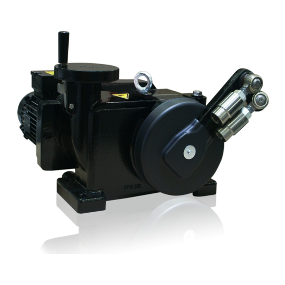
RHDE250 to RHDE4000 (Contrac)
Electrical rotary actuator
Introduction
—
RHDE250
RHDE500
Compact actuator for the operation of final control
RHDE800
RHDE1250
elements with preferably 90° rotary movement such
RHDE2500
as valve flaps, ball valves, etc.
RHDE4000
The nominal torque is transferred through a lever
actuator. A special electronic unit controls the
actuator. The special electronic unit serves as the
interface between actuator and control system.
Electrical rotary actuator for the
operation of final control elements
Additional Information
Additional documentation on RHDE250 / 500 / 800 /
1250 / 2500 / 4000 (Contrac) is available for
download free of charge at www.abb.com/actuators.
Alternatively simply scan this code:
Advertisement
Table of Contents

Related Manuals for ABB RHDE250 Series


Summary of Contents for ABB RHDE250 Series
- Page 1 90° rotary movement such 1250 / 2500 / 4000 (Contrac) is available for RHDE2500 as valve flaps, ball valves, etc. download free of charge at www.abb.com/actuators. RHDE4000 Alternatively simply scan this code: The nominal torque is transferred through a lever actuator.
-
Page 2: Table Of Contents
RHDE250 to RHDE4000 (Contrac) ELECTRICAL ROTARY ACTUATOR | OI/RHDE250_4000-EN REV. B Table of contents Change from one to two columns Safety ................3 Electronic Unit EBN853 (Contrac)........29 General information and instructions ........3 Analog / Digital ..............29 ... -
Page 3: Safety
RHDE250 to RHDE4000 (Contrac) ELECTRICAL ROTARY ACTUATOR | OI/RHDE250_4000-EN REV. B Change from one to two columns 1 Safety Warnings General information and instructions The warnings in these instructions are structured as follows: These instructions are an important part of the product and must be retained for future reference. -
Page 4: Intended Use
/ or theft of data or information. ABB Automation Products GmbH and its affiliates are not liable for damages and / or losses related to such security breaches, any unauthorized access, interference, intrusion, leakage and / or theft of data or information. -
Page 5: Use In Potentially Explosive Atmospheres
IP6x T=130 °C ZELM 04 ATEX 0209 X Monitoring can be performed using the ABB SD241-B monitoring Motor with brake II GD Ex de IIB T4 unit or a comparable certified tripping unit for thermistor... -
Page 6: Overview
RHDE250 to RHDE4000 (Contrac) ELECTRICAL ROTARY ACTUATOR | OI/RHDE250_4000-EN REV. B … 2 Use in potentially explosive atmospheres Overview Figure 1: Allocation of the Contrac components when using in potentially explosive atmospheres (example) -
Page 7: Technical Data For The Cable Set (For Ex-Relevant Range)
RHDE250 to RHDE4000 (Contrac) ELECTRICAL ROTARY ACTUATOR | OI/RHDE250_4000-EN REV. B Technical data for the cable set (for Ex-relevant range) Motor connection Motor temperature monitoring Signal terminal (option) Wire conductor 8 × 1.5 2 × 1.5 8 × 0.5 Mat.-No. 9280271 9280272 9280183... - Page 8 RHDE250 to RHDE4000 (Contrac) ELECTRICAL ROTARY ACTUATOR | OI/RHDE250_4000-EN REV. B … 2 Use in potentially explosive atmospheres … Technical data for the cable set (for Ex-relevant range) Option Motor connection Motor temperature monitoring Signal terminal (option) Manufacturer Pflitsch Pflitsch Type blue globe ATEX blue globe ATEX...
-
Page 9: Design And Function
RHDE250 to RHDE4000 (Contrac) ELECTRICAL ROTARY ACTUATOR | OI/RHDE250_4000-EN REV. B 3 Design and function Design M10575 1 Hand wheel crank 6 Output shaft 2 Handwheel 7 Adjustable stops (under the lever cover) 3 Ball-and-socket joint 8 Control motor 4 Output lever 9 Handwheel unlock 5 Lever cover Figure 2: RHD (illustrations may differ from actual installation) -
Page 10: Device Designs
RHDE250 to RHDE4000 (Contrac) ELECTRICAL ROTARY ACTUATOR | OI/RHDE250_4000-EN REV. B … 3 Design and function Device designs RHDE250 / 500 / 800 / 1250 / 2500 / 4000 (Contrac) Operating mode S9; stallproof acc. to EN 60034-1 IP rating IP 66 Explosion protection ATEX... - Page 11 RHDE250 to RHDE4000 (Contrac) ELECTRICAL ROTARY ACTUATOR | OI/RHDE250_4000-EN REV. B RHDE500-10 RHDE800-10 Nominal torque 500 Nm (370 lbf-ft), adjustable to 0.5, 0.75 or 800 Nm (590 lbf-ft), adjustable to 0.5, 0.75 or 1 × nominal torque 1 × nominal torque Starting torque 1.2 ×...
- Page 12 RHDE250 to RHDE4000 (Contrac) ELECTRICAL ROTARY ACTUATOR | OI/RHDE250_4000-EN REV. B … 3 Design and function … Device designs RHDE4000-10 RHDE4000-40 Nominal torque 4000 Nm (2950 lbf-ft), adjustable to 0.5, 0.75 or 1 × nominal torque Starting torque 1.2 × nominal torque (break-away torque in end positions for short time 2 × nominal torque) Rated time for 90°;...
-
Page 13: Product Identification
RHDE250 to RHDE4000 (Contrac) ELECTRICAL ROTARY ACTUATOR | OI/RHDE250_4000-EN REV. B 4 Product identification 5 Transport and storage Name plate Inspection Check the devices immediately after unpacking for possible damage that may have occurred from improper transport. Antrieb / ActuatorCONTRAC ..Details of any damage that has occurred in transit must be -Nr./No NL -/-... -
Page 14: Storing The Device
RHDE250 to RHDE4000 (Contrac) ELECTRICAL ROTARY ACTUATOR | OI/RHDE250_4000-EN REV. B … 5 Transport and storage 6 Installation Storing the device Safety instructions Note DANGER The storage data provided below assumes that the devices are fully closed and thus comply with the IP rating stated in the Danger to life due to falling or toppling loads. -
Page 15: Installation Instructions
RHDE250 to RHDE4000 (Contrac) ELECTRICAL ROTARY ACTUATOR | OI/RHDE250_4000-EN REV. B Installation instructions Mounting position • Make sure that no process forces are exerted on the final The spur gears of the actuator are oil lubricated. control element. They contain the max. oil quantity when leaving the •... -
Page 16: Assembly With The Final Control Element
RHDE250 to RHDE4000 (Contrac) ELECTRICAL ROTARY ACTUATOR | OI/RHDE250_4000-EN REV. B … 6 Installation … Mounting Assembly with the final control element Travel-dependent stop adjustment 1. Remove the lever cover. WARNING 2. Move the actuator lever / final control element to the end position requiring finer mechanical adjustment. -
Page 17: Installation Variants
RHDE250 to RHDE4000 (Contrac) ELECTRICAL ROTARY ACTUATOR | OI/RHDE250_4000-EN REV. B Installation variants Mounting with lever Locking and fastening elements Locking screws of mechanical limit stops Actuator Tightening torque Nm (lbf-ft) RHDE250 79 (58) RHDE500 / 800 195 (144) RHDE1250 / 2500 670 (494) RHDE4000 670 (494) - Page 18 RHDE250 to RHDE4000 (Contrac) ELECTRICAL ROTARY ACTUATOR | OI/RHDE250_4000-EN REV. B … 6 Installation … Mounting Installation with additional output elements Configuring the drive element hub When mounting an additional drive element instead of the The new output element is mechanically connected to the standard lever, the following installation conditions must be actuator shaft via a hole with feather key groove.
-
Page 19: Dimensions
RHDE250 to RHDE4000 (Contrac) ELECTRICAL ROTARY ACTUATOR | OI/RHDE250_4000-EN REV. B Dimensions Control actuator RHD250 Ø132 (5.20) 57,5 (2.26) 310 (12.20) 60 (2.36) 145 (5.71) 34 (1.34) 344 (13.54) 179 (7.05) 107 (4.21) 12 (0.47) 33 (1.30) M10248 1 S = Center of gravity 2 Removal dimension 3 Space for removing the plug Figure 7: Dimensions in mm (in) -
Page 20: Control Actuator Rhd500 / Rhd800
RHDE250 to RHDE4000 (Contrac) ELECTRICAL ROTARY ACTUATOR | OI/RHDE250_4000-EN REV. B … 6 Installation … Dimensions Control actuator RHD500 / RHD800 440 (17.32) Ø132 (5.20) 57,5 (2.26) 70 (2.76) 470 (18.50) 211 (8.31) 145 (5.71) 520 (50.47) 260 (10.24) 300 (11.81) -0.018 (-0.00071) 14 (0.55) -0.061 (-0.00240) -
Page 21: Control Actuator Rhd1250 / Rhd2500
RHDE250 to RHDE4000 (Contrac) ELECTRICAL ROTARY ACTUATOR | OI/RHDE250_4000-EN REV. B Control actuator RHD1250 / RHD2500 Ø180 (7.09) 81,5 (3.21) 192 (7.56) 600 (23.62) 90 (3.54) 630 (24.80) 278 (10.94) 690 (27.17) 22 (0.87) 345 (13.58) 20 (0.79) + 0.030 (+0.001181) 70 (2.76) +0.011 (+ 0.000433) M10247... -
Page 22: Control Actuator Rhd4000
RHDE250 to RHDE4000 (Contrac) ELECTRICAL ROTARY ACTUATOR | OI/RHDE250_4000-EN REV. B … 6 Installation … Dimensions Control actuator RHD4000 Ø180 (7.09) 81,5 (3.21) 192 (7.56) 600 (23.62) 90 (3.54) 278 (10.94) 630 (24.80) 690 (27.17) 22 (0.87) 360 (14.17) 25 (0.98) + 0.035 (+0.001378) 85 (3.35) + 0.013 (+0.000512) -
Page 23: Connection Pipe And Link Rod
RHDE250 to RHDE4000 (Contrac) ELECTRICAL ROTARY ACTUATOR | OI/RHDE250_4000-EN REV. B Connection pipe and link rod M10574 Figure 11: Link rod components and connection pipe dimensions RHDE250 RHDE500 / RHDE800 RHDE1250 / RHDE2500 RHDE4000 1 Cone 1:10 2 Welding bushings are part of shipment 3 Connection pipe 1 ¼... - Page 24 RHDE250 to RHDE4000 (Contrac) ELECTRICAL ROTARY ACTUATOR | OI/RHDE250_4000-EN REV. B … 6 Installation … Dimensions M10573 Figure 12: Link rod, all dimensions in mm (in)
- Page 25 RHDE250 to RHDE4000 (Contrac) ELECTRICAL ROTARY ACTUATOR | OI/RHDE250_4000-EN REV. B RHDE250 RHDE500 / RHDE800 RHDE1250 / RHDE2500 RHDE4000 100 to 120(3.94 to 4.72) 105 to 120(4.13 to 4.72) 100 to 140(4.33 to 5.51) 135 to 165(5.31 to 6.50) =L−(2×A) =L−(2×A) =L−(2×A) =L−(2×A)
-
Page 26: Electrical Connections
RHDE250 to RHDE4000 (Contrac) ELECTRICAL ROTARY ACTUATOR | OI/RHDE250_4000-EN REV. B Change from one to two columns 7 Electrical connections Safety instructions Conductor cross-section on electronic unit Note WARNING Detailed information on separate electronic units can be found in the corresponding data sheets. Risk of injury due to live parts! Risk of death or serious injuries due to electricity and unexpected machine movements. -
Page 27: Cable Glands
RHDE250 to RHDE4000 (Contrac) ELECTRICAL ROTARY ACTUATOR | OI/RHDE250_4000-EN REV. B Cable glands Installation information on the cable harness for actuators in DANGER Ex design The electrical connection between the Contrac electronic unit Risk of explosion! and the Contrac actuator can be established using the cable set Risk of explosion due to the use of unsuitable cable glands. -
Page 28: Connection Of Cable Shielding
RHDE250 to RHDE4000 (Contrac) ELECTRICAL ROTARY ACTUATOR | OI/RHDE250_4000-EN REV. B … 7 Electrical connections Connection of cable shielding Sensor-connection chamber 1. Insert screw. 2. .Unscrew the cover for the connection chamber 3. Cut the cable sheath to the required length. 4.... -
Page 29: Electronic Unit Ebn853 (Contrac)
RHDE250 to RHDE4000 (Contrac) ELECTRICAL ROTARY ACTUATOR | OI/RHDE250_4000-EN REV. B Electronic Unit EBN853 (Contrac) Analog / Digital Note The electrical connection is established via screw terminals on the control actuator and on the electronic unit. Sub distribution board Screen connected to both ends one-sided screening in further wiring possible SDB241-B... -
Page 30: Profibus Dp
RHDE250 to RHDE4000 (Contrac) ELECTRICAL ROTARY ACTUATOR | OI/RHDE250_4000-EN REV. B … 7 Electrical connections … Electronic Unit EBN853 (Contrac) PROFIBUS DP® Note The electrical connection is established via screw terminals on the control actuator and on the electronic unit. Sub distribution board Screen connected to both ends one-sided screening... -
Page 31: Analog / Digital
RHDE250 to RHDE4000 (Contrac) ELECTRICAL ROTARY ACTUATOR | OI/RHDE250_4000-EN REV. B Electronic Unit EBN861 (Contrac) Analog / Digital Note • The electrical connection is established via screw terminals on the control actuator and on the electronic unit. • If you are using a separate heat supply, the heater must be protected with a 2 to 6 A medium time-lag fuse (e.g. NEOZED D01 E14). Sub distribution board Screen connected to both ends one-sided screening... -
Page 32: Profibus Dp
RHDE250 to RHDE4000 (Contrac) ELECTRICAL ROTARY ACTUATOR | OI/RHDE250_4000-EN REV. B … 7 Electrical connections … Electronic Unit EBN853 (Contrac) PROFIBUS DP® Note • The electrical connection is established via screw terminals on the control actuator and on the electronic unit. •... -
Page 33: Analog / Digital
RHDE250 to RHDE4000 (Contrac) ELECTRICAL ROTARY ACTUATOR | OI/RHDE250_4000-EN REV. B Electronic unit EBS852 (Contrac) / EBS862 (Contrac) Analog / Digital Note • The electrical connection is established via screw terminals on the control actuator and on the electronic unit. •... -
Page 34: Commissioning
RHDE250 to RHDE4000 (Contrac) ELECTRICAL ROTARY ACTUATOR | OI/RHDE250_4000-EN REV. B 8 Commissioning Automatic mode / Handwheel mode Note It is imperative that you observe the operating instruction of the corresponding electronic unit for the commissioning of the WARNING actuator. Risk of injury due to live parts! Risk of death or serious injuries due to electricity and unexpected machine movements. -
Page 35: Handwheel Operation In Combination With Positioning Loop Monitoring
RHDE250 to RHDE4000 (Contrac) ELECTRICAL ROTARY ACTUATOR | OI/RHDE250_4000-EN REV. B Handwheel operation in combination with positioning loop monitoring The positioning loop monitoring of the electronic unit monitors actuator behavior. The electronic unit monitors whether the travel commands trigger the corresponding processes. When the supply voltage is switched off, the positioning time- out function is disabled and handwheel operation is no longer monitored. -
Page 36: Diagnosis / Error Messages
RHDE250 to RHDE4000 (Contrac) ELECTRICAL ROTARY ACTUATOR | OI/RHDE250_4000-EN REV. B 10 Diagnosis / error messages This chapter only covers hardware-related errors. For additional troubleshooting information, refer to the online help for the operator interface. Error Possible cause Troubleshooting the Instrument Valve cannot be moved by actuator. -
Page 37: Maintenance
RHDE250 to RHDE4000 (Contrac) ELECTRICAL ROTARY ACTUATOR | OI/RHDE250_4000-EN REV. B 11 Maintenance General Safety instructions Contrac actuators feature a robust construction. As a result, WARNING they are highly reliable and require minimal maintenance. The maintenance intervals depend upon the effective load and are Risk of injury due to live parts! therefore not specified here. -
Page 38: Removing The Motor And Adjusting The Brakes
RHDE250 to RHDE4000 (Contrac) ELECTRICAL ROTARY ACTUATOR | OI/RHDE250_4000-EN REV. B … 11 Maintenance Removing the motor and adjusting the brakes Oil types WARNING Risk of injury! Ambient temperature Oil types − DIN 51517 The actuator position may be changed accidentally by the Default oil filled with delivery Alternative oil repelling power of the valve when the motor is removed or the brake is released. -
Page 39: Repair
The product must be supplied to a specialist recycling purposes: company. Do not use municipal waste collection points. All devices delivered to ABB must be free from any hazardous These may be used for privately used products only in materials (acids, alkalis, solvents, etc.). -
Page 40: Approvals And Certifications
Machinery Directive 2006/42/EC / 2006/42/EG • Low Voltage Directive 2014/35/EU • RoHS II Directive 2011/65/EU (as of 7/22/2019) 15 Additional documents Note All documentation, declarations of conformity and certificates are available in ABB's download area. www.abb.com/actuators Change from two to one column... -
Page 41: Appendix
RHDE250 to RHDE4000 (Contrac) ELECTRICAL ROTARY ACTUATOR | OI/RHDE250_4000-EN REV. B 16 Appendix Return form Statement on the contamination of devices and components Repair and/or maintenance work will only be performed on devices and components if a statement form has been completed and submitted. -
Page 42: Installation Declaration
RHDE250 to RHDE4000 (Contrac) ELECTRICAL ROTARY ACTUATOR | OI/RHDE250_4000-EN REV. B … 16 Appendix Installation declaration Change from one to two columns... - Page 43 RHDE250 to RHDE4000 (Contrac) ELECTRICAL ROTARY ACTUATOR | OI/RHDE250_4000-EN REV. B Trademarks HART is a registered trademark of FieldComm Group, Austin, Texas, USA PROFIBUS and PROFIBUS DP are registered trademarks of PROFIBUS & PROFINET International (PI)
- Page 44 We reserve the right to make technical changes or modify the contents of this document without prior notice. With regard to purchase orders, the agreed particulars shall prevail. ABB does not accept any responsibility whatsoever for potential errors or possible lack of information in this document.