
Related Manuals for GE MDS SD4A


Summary of Contents for GE MDS SD4A
- Page 1 MDS SD4 Series Secure, Long Range IP/Ethernet & Serial Covering ES/SS Units with Firmware Version 4.x MDS 05-4846A01, Rev. 01 Anatel Homologation Manual JULY 2011...
- Page 2 Need Quick-Start instructions for this product? Please refer to publication 05-4847A01. All GE MDS user guides are available online at www.gemds.com...
-
Page 3: Table Of Contents
TABLE OF CONTENTS 1.0 INTRODUCTION ........................1 1.1 Conventions Used in This Manual ....................1 2.0 PRODUCT DESCRIPTION....................3 2.1 Front Panel Connectors and Indicators ..................3 2.2 Key Product Features ........................4 Media Access Control (MAC)......................4 VLAN Capability..........................5 Terminal Server Capability ....................... - Page 4 5.0 STEP-BY-STEP INSTALLATION ..................26 5.1 Initial Configuration ........................27 Web-Based Management ......................27 Alternative Management Methods ....................28 Web Browser Connection ......................28 5.2 Initial Startup & Checkout ......................30 Ethernet Connector LEDs ......................31 5.3 Optimizing the Radio Network ..................... 31 Modem Type Setting ........................
- Page 5 9.0 GLOSSARY OF TERMS & ABBREVIATIONS ..............98 Copyright and Trademark This manual and all software described herein is protected by Copyright: 2011 GE MDS, LLC. All rights reserved. GE MDS, LLC reserves its right to correct any errors and omissions in this publi- ® cation. Modbus is a registered trademark of Schneider Electric Corporation.
- Page 6 If you have additional ques- tions or need an exact specification for a product, please contact GE MDS using the information at the back of this guide. In addition, manual updates can often be found on our web site at www.gemds.com.
- Page 7 These systems will reuse or recycle most of the materials found in this equipment in a sound way. Please contact GE MDS or your supplier for more information on the proper dis- posal of this equipment.
- Page 8 THIS SOFTWARE IS PROVIDED BY THE COPYRIGHT HOLDERS AND CONTRIBUTORS “AS IS” AND ANY EXPRESS OR IMPLIED WARRANTIES, INCLUDING, BUT NOT LIM- ITED TO, THE IMPLIED WARRANTIES OF MERCHANTABILITY AND FITNESS FOR A PARTICULAR PURPOSE ARE DISCLAIMED. IN NO EVENT SHALL THE COPYRIGHT OWNER OR CONTRIBUTORS BE LIABLE FOR ANY DIRECT, INDIRECT, INCIDENTAL, SPECIAL, EXEMPLARY, OR CONSEQUENTIAL DAMAGES (INCLUDING, BUT NOT LIMITED TO, PROCUREMENT OF SUBSTITUTE GOODS OR SERVICES;...
-
Page 9: Introduction
Setup Guide is limited to installing the transceiver and placing it in service for the first time. All product documentation may be downloaded free of charge from the GE MDS website at www.gemds.com . The website also contains links to Application Bulletins and other product information. - Page 10 Authorization Some features of the radio are dependent on purchased options and Features applicable regulatory constraints. A “key” icon is shown near the heading of any such features. In some cases a feature upgrade may be available. Contact your sales representative for additional information. SD Series Technical Manual MDS 05-4846A01, Rev.
-
Page 11: Product Description
2.0 PRODUCT DESCRIPTION The SD Transceiver is a software-configurable, industrial radio for use in licensed data acquisition networks. It may be interfaced with a variety of data control equipment including remote terminal units (RTUs), pro- grammable logic controllers (PLCs), flow computers, and similar devices. -
Page 12: Key Product Features
2.2 Key Product Features The transceiver is designed to meet the demanding needs of today’s wireless networks in a compact, and rugged package. It offers an array of features in a single hardware platform: • Software-configurable via a built-in Device Manager—no man- ual controls or adjustments. -
Page 13: Vlan Capability
to use the RF channel before sending payload data, thus avoiding colli- sions of data, and creating a highly reliable wireless network. The MAC is responsible for allocating which unit gets access to the broadcast medium (the RF channel), when, and for how long. Additionally, the MAC validates all messages and purges corrupted data Data Validation from the system. -
Page 14: Sd Model Offerings
2.3 SD Model Offerings The radio is offered in three model types, using one hardware platform: • Ethernet—All SD features and functionality • Standard—All SD features, except over-the-air Ethernet data • x710—Direct, drop-in compatibility for networks using a mix of SD and older MDS x710 radios Model Number The unit’s complete model number is printed on the bottom label. -
Page 15: Accessories And Spares
(see Table 1). 2.5 Accessories and Spares Table 1 lists common accessories and spare items for the transceiver. GE MDS also offers an Accessories Selection Guide listing additional www.gemds.com items that may be used with the product. Visit or contact your factory representative to obtain a copy of the guide. -
Page 16: Protected Network Station
Table 1. Accessories & Spare Items (Continued) Accessory Description Part Number DIN Rail Mounting Contains bracket for mounting the 03-4125A04 Bracket Kit transceiver to standard 35 mm DIN rails commonly used in equipment cabinets and panels. Reprogramming Automated software program for 06-6241A01 Application for upgrading the radio’s internal... -
Page 17: Dual Protected Configurations
Dual Protected Configurations Two dual transceiver configurations are offered for the SD Series. They are known as the SDxDT and the SDxDP. These configurations are used for the following purposes: • When full duplex operation is desired using dedicated Transmit and Receive transceivers. -
Page 18: Typical Applications
A number of variations are possible; If you have unique requirements not found here, it is recommended that you consult a support specialist at GE MDS. Contact information is provided at the back of this manual. 3.1 Operating Parameters The transceiver can operate in both poll-response and “push”... -
Page 19: Example Systems
3.2 Example Systems The following sections describe common system arrangements for the SD transceiver. Other variations are possible, and if you have questions about a specific application not covered here, you may contact your fac- tory representative using the information at the back of this guide. For typical radio settings in these systems, refer to Table 2 on Page 10. -
Page 20: Ip/Ethernet Polling And Terminal Server Operation
Invisible place holder HOST COMPUTER REMOTE RADIO MASTER RADIO Figure 6. Typical Point-to-Point Link IP/Ethernet Polling and Terminal Server Operation Modern data/control networks often employ IP/Ethernet connectivity throughout the system. The SD transceiver is well suited to provide con- nectivity between such sites using its RJ-45 modular connector on the front panel and enabling Ethernet Bridging capabilities. -
Page 21: Port Sharing With Multiple Hosts
This type of network can also be used for general Ethernet bridging as supported by the over-the-air bandwidth of the system. Bridge filters are available to reduce Ethernet traffic over the RF channel, and improve performance. Port Sharing with Multiple Hosts The transceiver allows for several external data networks to use the same RF network without confusing the data streams. -
Page 22: Push Communication (Report-By Exception)
Device Settings Screen Radio Mode: Packet w/MAC MASTER RADIO To Ethernet Port HOST COMPUTER (Host B) HOST COMPUTER (Host A) Ethernet Serial HOST C To COM2 Serial Port REMOTE RADIO REMOTE RADIO (One of several possible sites) (One of several possible sites) Ethernet Co-located RTUs Responding to... -
Page 23: Serial Remotes With Two Serial Ports
In this example, the Host Computer is connected directly to the radio’s Ethernet port, and the RTUs at the Remote sites are connected to the COM2 transceiver via the radio’s serial data ports. The IP Payload fea- ture, used at the Master, efficiently passes TCP payload over the air, and COM1 eliminates the need for an external terminal server. - Page 24 Packet With MAC is the recommended method of operation when both serial ports are used to pass payload data if there are two hosts (e.g., Port Sharing with multiple host case). If there is a single host polling all units, packet or transparent mode is the preferred option (depending on whether encryption is required or not) even if there are two RTUs con- nected to a Remote radio.
-
Page 25: Installation Planning
4.0 INSTALLATION PLANNING This section discusses the factors to be considered before installing the radio. Careful planning of the installation site will help achieve optimal performance from the transceiver. Step-by-step installation procedures begin on Page 26. Figure 11 shows a typical remote station arrangement. The specific details at an installation site may vary, but there are three main requirements for installing the transceiver in all cases: •... -
Page 26: Optional Din Rail Mounting
Invisible place holder 6.675˝ (16.95 cm) Figure 12. Mounting Bracket Dimensions NOTE: To prevent moisture from entering the radio, do not mount the case with the cable connectors pointing up. Also, dress all cables to prevent moisture from running along the cables and into the radio. Optional DIN Rail Mounting The unit may be mounted with an optional 35 mm DIN Rail Mounting Bracket Kit (Part No. -
Page 27: Antennas And Feedlines
Antennas of this type are available from several manufacturers, including GE MDS. Contact your factory representative for details. Invisible place holder Figure 14. Typical Yagi Antenna (mounted to mast) Feedlines The selection of an antenna feedline is very important. -
Page 28: Dc Power Connection
Table 3, Table 4, and Table 5 show the approximate losses that will occur when using various lengths and types of coaxial cable in the 200, 400 and 960 MHz bands, respectively. Regardless of the type used, the cable should be kept as short as possible to minimize signal loss. Table 3. -
Page 29: Grounding Considerations
A power connector with screw-terminals is provided with each unit (see Figure 15). Strip the wire leads to 6 mm (1/4 inch) and insert in the wire ports, tightening securely. Be sure to observe proper polarity as shown in Figure 15. Invisible place holder Lead Binding... -
Page 30: Serial Data Interfaces
NOTE: Not all PCs have a serial port. If one is not available, a USB-to-Serial adapter and appropriate driver software may be used to provide serial connectivity. These adapters are avail- able from several manufacturers, including GE MDS. SD Series Technical Manual MDS 05-4846A01, Rev. F... -
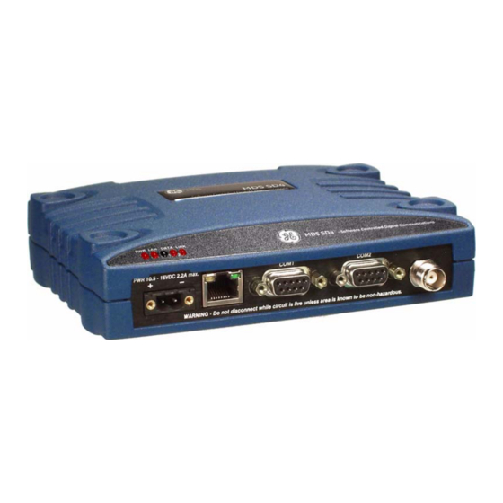
Page 31: Com1 (Serial) Connection
COM1 (Serial) Connection COM1 The default factor settings for the radio’s port (Figure 17) assigns it for management or diagnostics of the radio via a serial connection to COM1 a PC. may be used to set basic parameters such as output power, modem type and operating frequency of the radio. -
Page 32: Com2 (Data) Connections
Table 7. COM1 Pin Descriptions Radio Number Input/ Pin Description Output No function No function in most applications—User I/O for special applications No function No function in most applications—User I/O for special applications COM2 (Data) Connections COM2 Typically, the port (Figure 19) is used for connecting the radio to an external DTE serial device supporting the RS-232 or RS-485 serial data format. - Page 33 Table 8. COM2 Pin Descriptions—Radio in RS-232 Radio Number Input/ Pin Description Output CTS (Clear-to-Send)—Goes “high” after the programmed CTS delay time has elapsed (DCE), or keys another connected radio when RF data arrives (CTS KEY). Reserved—User I/O for special applications Table 9.
-
Page 34: Step-By-Step Installation
5.0 STEP-BY-STEP INSTALLATION In most cases, the steps given here are sufficient to install the trans- ceiver. Refer to “INSTALLATION PLANNING” on Page 17 for addi- tional details, as required. 1. Mount the transceiver. Attach the mounting brackets to the bottom of the transceiver case (if not already done), using the four 6-32 x 1/4 inch (6 mm) screws supplied. -
Page 35: Initial Configuration
5. Configure Basic Settings. Connect a PC to the radio’s Ethernet connector. Access the radio’s Device Manager through the PC’s browser. On a factory default radio, the Device Manager automati- cally starts the Basic Setup Wizard. The wizard steps you through the essential radio settings in streamlined fashion. -
Page 36: Alternative Management Methods
COM1 • Serial—( DB9 connector). This is the “console terminal” method of control commonly used on earlier GE MDS radios. For more information, refer to the Serial/Tenet Management Supple- www.gemds.com ment available from the GE MDS website at ETHERNET •... - Page 37 2. Configure your PC network settings to an IP address on the same 255.255.255.0 subnet as the radio. The default subnet mask is 3. Enter the radio’s IP address in a web browser window, just as you would enter a website address. When the login screen appears (Figure 1), enter the User Name and Password for the radio.
-
Page 38: Initial Startup & Checkout
Invisible place holder Figure 22. Basic Setup Wizard Done 5. At the conclusion of the wizard, click . Configuration is now complete for the connected radio. Log out of the Device Manager by Logout clicking in the upper right hand side of the screen. If desired, you may proceed with the additional functions described below. -
Page 39: Ethernet Connector Leds
3. If not done earlier, refine the antenna heading of the station to maxi- mize the received signal strength (RSSI) from the Master Unit. The Performance screen may be used to observe RSSI. Turn the antenna heading slowly so that the RSSI display can be updated. NOTE: The RSSI facility limits the maximum displayed signal strength to –60 dBm. -
Page 40: Inter-Packet Gap Settings
Inter-Packet Gap Settings For radios operating in Packet Mode, the inter-packet gap is a timing set- ting used to delimit a packet on the serial interface. Too short of a time can cause serial streams to be combined into one large packet instead of two smaller ones. -
Page 41: Antenna Swr Check
Antenna SWR Check Before placing the radio into final service, a check should be made of the antenna system’s standing wave ratio (SWR). Use a directional watt- meter suited to the frequency of operation for this check. High SWR (above 2:1) may indicate an antenna, connector, or feedline problem, and should be corrected. -
Page 42: Using The Device Manager
6.0 USING THE DEVICE MANAGER The radio contains a built-in management system known as a Device Manager. This web-based tool is accessed with a PC connected to the radio’s Ethernet port as shown in Figure 23. It offers an intuitive, easy to use method for managing your radio and performing common main- tenance tasks. -
Page 43: Overview Screen
Invisible place holder Figure 24. Overview Summary Screen Overview Screen The Overview screen (Figure 24) provides a read-only view of all key Health & Maintenance settings and operating conditions for the radio. The Summary , in particular, can help you quickly spot changes in operating conditions. -
Page 44: Management Tasks
6.2 Management Tasks Table 11 shows a listing of commonly-needed tasks and the appropriate sections of the Device Manager to refer to. The table can be used as a quick reference before consulting the more detailed screen information which follows in this section. Table 11. - Page 45 Table 11. Common Tasks with Device Manager (Continued) Task If you wish to... Refer to this Screen Category Set RF Output Power, Modem Type, RX/TX Configuration>>Radio, Frequency Basic Settings, Page 41 View/Set Soft-Carrier Dekey status, RX/TX Configuration>> Time-Out options Radio>> Advanced Settings, Page 48 Data-Key and RTS-Key settings (ON/OFF) Configuration>>...
- Page 46 Table 11. Common Tasks with Device Manager (Continued) Task If you wish to... Refer to this Screen Category View Serial No., Model 1 (hardware), Model 2 Overview>> (software) version, Firmware Version, Build SD Summary, Page 35 Date Set Owner Name/Message, enable/disable Configuration>>...
- Page 47 Table 11. Common Tasks with Device Manager (Continued) Task If you wish to... Refer to this Screen Category Configure COM1 settings (Startup mode, Data Configuration>> Baud Rate, Data format, Virtual Radio Communication Ports>> Channels–VRCs) COM1 Port Settings, Page 63 Configure COM2 settings (Mode, Baud Rate, Configuration>>...
- Page 48 Table 11. Common Tasks with Device Manager (Continued) Task If you wish to... Refer to this Screen Category View logged Events Maintenance & Status>> Event Log, Page 69 Set alarm signal output (active high/low) Maintenance & Status>> Alarm Summary>> Alarm Signal Configuration, Page 70 Issue Alarm Test Maintenance &...
-
Page 49: Configuration Screens
6.3 Configuration Screens The Configuration screen (Figure 25) contains a number of key settings for the radio, including RF parameters, modem selection, packet set- tings, MAC parameters, and several advanced settings. Individual Configuration screens may be selected beneath on the left side of the screen. - Page 50 Modem Type • —This setting determines the over-the-air data speed and bandwidth of the radio’s transmitted signal. All radios in the network must use the same modem setting to communicate with Modem 9600 each other. The default setting is , but it may be set to any of the selections shown in Table 12.
- Page 51 Device Settings Owner Name/Owner Message • —An owner name and message may be entered for the radio for informational purposes. These are “free-form” fields which do not affect the operation of the radio in any way. Such fields might be used to identify the network administrator/company name, and include a site-specific message Unit 2 at North Tower site (i.e.,...
- Page 52 Radio Mode • —The radio can operate in one of several modes. The available selections are: Packet, Packet with MAC, x710, and Transparent. User Interface • —This parameter selects the method of radio man- Menu agement. The default selection is , which presents the type of screens shown in this manual.
-
Page 53: Store And Forward Operation
Remote must have a unique Unit Address, however, which is set on the Diagnostic Settings screen (see below). A Store and For- ward device is a radio designated to retransmit data to/from an outlying Remote (see SAF Network, below). SAF Network •... - Page 54 Invisible place holder Figure 26. Store and Forward System Example Store and Forward is available in Packet with MAC mode and supports all MAC features including collision avoidance, retries, and acknowl- edgements. Furthermore, all major radio features are supported in SAF networks such as diagnostics, over the air programming, bridging, VRCs, etc.
- Page 55 Initially, all Remote device routes are unknown. The AP assumes that all undiscovered Remotes can potentially be on the SAF link. Once a Remote attempts to communicate upstream to the AP, the AP is aware of the Remote's path based on the exchange type, direct or SAF. The AP stores this information in a database linked to the Remote's address.
- Page 56 Advanced Settings Soft-Carrier Dekey (ms) • —Specifies how long (in ms) to wait after the removal of the keying signal before actually dropping the transmitter’s carrier. The default setting is , but it may be set to any value up to ms.
- Page 57 Push-To-Talk Delay (ms) • —Allows programming a brief time delay after a keying event, which must expire before the radio is allowed to transmit. The allowable range is 0 to 255 ms, with the default being 0. Clear-To-Send Delay (ms) •...
-
Page 58: Features
Features Bridge Configuration Bridge Mode • —Used to enable or disable Ethernet Bridging on the radio. Default setting is Basic Bridge Filter Sel • —Sets the type of bridge filter to be used. Broadcast/Unicast (All), Unicast and ARP, Available selections are: Unicast Only Adv Bridge Filter Status •... - Page 59 When the Ethernet port of a Remote radio is configured as a VLAN trunk, the radio expects all incoming Ethernet frames to be tagged, and passes through all outgoing frames as received from the wireless link with the unchanged VLAN tag. Mode Trunk Access...
- Page 60 Listen Before Transmit • —Used to activate or deactivate LBT when this feature is authorized in the radio. LBT Behavior • —LBT can be configured to behave in one of two ways; either listen on the radio’s transmit frequency (TX) or listen on the radio’s receive frequency (RX).
- Page 61 Timeout (ms) • —Provides a setting for the maximum time to wait (in milliseconds) for the channel to become free. When this time is Packet Action exceeded, the radio follows the action defined in the on Timeout Drop Send setting (either Packet Action on Timeout •...
- Page 62 The Master radio then sends the response back to the polling station via Ethernet. When configuring this feature, you are notified of the success or failure of the operation. Additionally, Ethernet and OTA statistics can be monitored to inspect the success of the poll-response communication. The following additional points apply to Ethernet payload operation: •...
-
Page 63: Understanding The Use Of Virtual Radio Channels (Vrcs)
Destination IP Port • —Used to specify a port number for the RJ-45 modular connector on the connected device (typically a PC). Port numbers below 2000 should be avoided, as some are reserved for special applications in data networks. TCP Server IP Address •... - Page 64 Invisible place holder RADIO 1 IP Payload 1 Data (Talk on VRC-1) Serial COM2 Data (Talk on VRC-2) RADIO 2 IP Payload 1 Data (Listen on VRC-1) Serial COM2 Data (Listen on VRC-2) Ethernet/IP RTU Serial-Based RTU Figure 27. Virtual Radio Channel (VRC) Concept Commit Configuration IP Payload After making configuration changes, click...
- Page 65 Local Radio IP Port The Local Radio IP Port setting is used to specify a port number for the RJ-45 modular connector on the radio’s front panel. Port numbers below 2000 should be avoided, as some are reserved for special applications in data networks.
- Page 66 Terminal Server The radio’s Terminal Server feature allows IP addressing of the COM1 COM1/2 and COM2 serial interface ports. Data from these ports is sent over the Configuration air as encapsulated IP packets. At the receiving end, the data is decapsu- lated and delivered to the appropriate COM port(s).
-
Page 67: Using The Terminal Server-Typical Example
Persistent Connection • —When set to , the connection to the server is maintained continuously, even during periods of inactiv- ity. The Terminal Server supports the following communication protocols: • Point-to-Point: TCP or UDP • Point-to-Multipoint : UDP (One of the Destination IP Addresses is a multicast IP address) •... - Page 68 Serial Addressability This example shows that it is possible to communicate to specific serial devices (e.g., PC 2 COM1, and PC 3 COM1) over the radio network. Note that TCP is used as the transport layer for communication here, which provides data reliability at the application level. Term Srvr 2 1.
- Page 69 Invisible place holder Figure 30. Remote 1 COM2 Port Connection On PC1, open a HyperTerminal session and connect to Remote 2 Ter- minal Server as shown in Figure 31. Invisible place holder Figure 31. Remote 2 Terminal Server Connection On PC3, open a HyperTerminal session and connect to Remote 2’s COM2 port as shown in Figure 32.
- Page 70 Type “hello” in the Remote 1 terminal server window. Note delivery of the message only to the Remote 1 COM2 Port window (see Figure 33). Type “hi” in the Remote 1 COM2 port window. Note delivery of mes- sage only to the Remote 1 terminal server window. This verifies proper delivery and routing of traffic.
-
Page 71: Communications Ports
Packet with MAC operation replaces multihost operation, and is the rec- ommended method for passing multiple data streams. See “Device Set- tings” on Page 43 for instructions on setting the Radio Mode to Packet with MAC. Multihost Enable • —Enables or disables multihost capability. Multihost Delay •... - Page 72 7 character bits, odd parity, 1 stop bit 7 character bits, odd parity, 2 stop bits 7 character bits, even parity, 1 stop bit 7 character bits, even parity, 2 stop bits Talk on/Listen to • —Any combination of the three Virtual Radio Channels may be entered in these fields.
- Page 73 7 character bits, odd parity, 1 stop bit 7 character bits, odd parity, 2 stop bits 7 character bits, even parity, 1 stop bit 7 character bits, even parity, 2 stop bits Buffer • —The transceiver’s buffer provides a way of handling data COM2 “over-runs,”...
-
Page 74: Security
Current IP Address • —Read-only indication of the current IP address programmed. Current Subnet Mask • —Read-only indication of the subnet mask programmed. Current Default Gateway • —Read-only indication of the current default gateway programmed. Static IP Address • —The radio requires a local IP address to support remote management and serial device (terminal server) services. - Page 75 Required might be useful in cases where only a small number peo- ple with administrative duties have physical access to the radio, and need to access the menu frequently. In this mode, the menu operation behaves identically to the Administrator level login. Telnet Access •...
-
Page 76: Maintenance & Status Screen
TIP: For enhanced security, consider using misspelled words, a combi- nation of letters and numbers, and a combination of upper and lower case letters. Also, the more characters used (up to 13), the more secure the password will be. These strategies help protect against sophisticated hackers who may use a database of common words (for example, dictionary attacks) to determine a password. -
Page 77: Event Log
Event Log The Event Log is used to display all events stored by the transceiver, even if the radio has been power-cycled. It also shows a running total of the alarms stored. Total Event Log Events • —Displays the number of events that have Show been logged by he transceiver. - Page 78 Status Conditions This screen shows status conditions reported since power-up of the and Events transceiver. This includes normal, informational events such as booting up the system and reinitializing. Refresh • —Clicking this button manually updates the listed events with the latest information. Auto •...
-
Page 79: Performance
Never assert Alarm Signal Assert Signal on Major Alarm Assert Signal on Major or Minor Alarm Assert Signal on Any Alarm or Status Set Alarm Bits • —This button is used to set the selections made in the check box list below it. First, you must select which specific alarms will result in a signal being produced by the alarm output line. - Page 80 I/O Statistics This screen allows viewing transmitted and received bytes on any of the transceiver interface modules. Module Select • —The drop-down box to the right of this area allows Media selection of any of the transceiver interface modules: Access Controller Port(s) COM1 COM2...
-
Page 81: Radio Test
Radio Test The Radio Test functions are a collection of tools useful for testing the RF performance of the transceiver. It provides a way to key (activate) the transmitter, measure power output, run a spectrum test, and enable the built-in RTU simulator. The unit’s built-in RTU simulator generates random data similar to what RTU Simulator would be supplied by an external RTU connected to the radio. - Page 82 NOTE: No other data traffic should be active when performing a Link- test. Destination Unit Address • —Enter the Unit Address of the other radio being tested. Linktest Count • —Enter the number of times for the message to be sent across the radio link.
- Page 83 RF Keying Test The RF Keying Test screen provides a way to place the transmitter on the air to check the measured RF power output, measure reflected power from an antenna system, or to provide a signal at a receiving station so that RSSI can be checked.
-
Page 84: Firmware Utilities
Alarm Test The Alarm Test screen provides a way to force an alarm for testing Commit alarm reporting and radio response. When set to , clicking the Configuration button sets an alarm, and the radio’s LED begins to flash. An “Alarm Test” entry is also made in the Event Log, and the external alarm output status is changed. - Page 85 Reprogramming *.mpk In the space provided, enter the file to reprogram into this radio, Program then click to start the file upload process. Do not click away from this page until the upload has finished processing. The TFTP Reprogramming screen contains settable parameters for TFTP Reprogramming TFTP file transfers and selections for Importing/Exporting configura-...
- Page 86 Remote The transceiver has facilities for reprogramming key settings of other Reprogramming radios in the network. These functions are contained on the Remote Reprogramming screen shown below. Additional information on remote reprogramming is given in “Over-the-Air Firmware Upgrades” on Page 89. Channel Usage •...
- Page 87 Verify Image This screen is used to verify the integrity of an image stored in flash memory. You may wish to verify an image after reprogramming or as part of a troubleshooting sequence. Verify • —Click this button to verify the firmware image selected in the drop-down box at the top of the screen.
- Page 88 Device Reboot Active Image • —Shows the firmware package currently being used by the transceiver (1 or 2). Package 1 • —Shows the version of firmware package 1. Package 2 • —Shows the version of firmware package 2. Image • —Allows selection of the firmware image to use when Current active Image, Image 1, Image 2, Inactive Image rebooting:...
-
Page 89: Configuration Files
Configuration Files The transceiver provides a Dump/Load Configuration File utility to ease Dump/Load Configuration File programming of operating parameters. This is especially useful if you have a large number of radios to configure, or simply want to ensure that each radio is uniformly configured. Dump Current Config •... - Page 90 Save/Restore This screen allows saving or restoring a configuration file for the trans- Configuration ceiver. Saving a configuration file can be helpful in future trouble- shooting tasks, as it allows reverting to a “known good” configuration of the radio. Restore to Factory Defaults •...
-
Page 91: Troubleshooting
TROUBLESHOOTING Successful troubleshooting of the radio system requires a logical approach. It is best to begin troubleshooting at the master unit, as the rest of the system depends on the master for polling commands. If the master unit has problems, the overall operation of the network will be affected. It is good practice to start by checking the simple things. -
Page 92: Led Indicators
Correct as necessary. c. Re-enable Sleep Mode on Device Settings Screen, re-connect device to COM2, and check for proper operation. Password lost or Contact GE MDS for password reset authorization code. forgotten Proof of authorized user required. Alarm message No load on Antenna connector or poor/shorted/open load. -
Page 93: Checking For Alarms/Events
Checking for Alarms/Events When an alarm condition exists, the transceiver registers it as an Maintenance “event”. These events can be viewed the Device Manager’s & Status>>Alarm Summary>>All Alarms/Events screen. Here, users can check for currently active alarms, whether they be Major, Minor, Status Con- ditions, or Informational Events. -
Page 94: Event Code Definitions
Table 15 contains a listing of event codes that may be reported by the transceiver. The codes shown are a subset of a larger pool of codes used for various GE MDS products. For this reason, the table does not show a sequential listing of all code numbers. Only the codes applicable to this product series are shown. -
Page 95: Operating Constraints
Table 15. Event Codes (Continued) Event Event Code Class Description Minor #27 Reserved. Minor #28 Reserved. Minor RF Output Power not in valid range. Minor #30 Reserved. Minor Internal temperature approaching limit. Minor Unexpectedly executing APP 1. Minor Unexpectedly executing APP 2. Minor Boot error;... -
Page 96: Technical Reference
8.1 Performing Network-Wide Remote Diagnostics Diagnostics data from a remote radio can be obtained by connecting a laptop or personal computer running GE MDS diagnostic software, such as MDS PulseNET or MDS InSite to any radio in the network. Figure 37 shows a sample arrangement for performing network-wide remote diag- nostics. -
Page 97: Setting Up Diagnostics
With a PC connected to any radio in the network, intrusive polling (polling that interrupts payload data transmission) can be performed. To perform diagnostics without interrupting payload data, connect the PC to a radio defined as the “root” radio. This is defined using the Device Manager on a connected PC. -
Page 98: Intrusive Vs. Passive (Non-Intrusive) Mode
Intrusive vs. Passive (Non-Intrusive) Mode Firmware code may be transmitted to stations in either intrusive or pas- sive (non-intrusive) mode using the built-in diagnostic capabilities of the radio. When OTA reprogramming is initiated from either a root or node the firmware image is broadcast to all Remotes in intrusive or pas- sive use of the channel. -
Page 99: Ota Reprogramming Overview
The disadvantage to passive operation is that it takes longer to convey the reprogramming information since it is must be attached to existing data transactions. See Table 18 for the approximate times needed for passive reprogramming. Table 18. Approximate Reprogramming Times—Passive Mode Modem Speed Approximate Time Required (bps) -
Page 100: Cancelling Ota Reprogramming
Receiving stations can automatically reboot to the new image after suc- cessful reprogramming. Alternatively, there is an OTA reboot command that can be broadcast from the initiator to all receiving stations. This last option instructs the receivers to reboot to a specific firmware revision if available, and not already running at that revision. -
Page 101: Com1 Operating Modes
Data mode or Manage- ment mode, where user input can be accepted via either a menu inter- face, a command line interface, or a diagnostic interface such as GE MDS-proprietary DLINK protocol. The list below shows all possible... -
Page 102: Implementing Sleep Mode
8.4 Implementing Sleep Mode Sleep Mode places the transceiver into a low power “hibernating” state, with a nominal current draw of less than 10 mA (at 13 Vdc) and a “wake-up” time of approximately 50 milliseconds. Sleep Mode is often used at battery/solar-powered sites to conserve power. -
Page 103: User-Programmable I/O Functions
and wait for a poll and response before lowering it again. Connect the COM2 RS-232 line to Pin 4 of the radio’s port. This allows each Remote to be polled once per hour with a significant savings in power consump- tion. - Page 104 FCC ID: SD4: E5MDS-SD4 IC ID: SD4: 101D-SD4 FCC Emission Designators (SD4): 6.25kHz B/W (MODEM 4800F): 6K00F1D, F2D, F3D 12.5 kHz B/W (MODEM 9600, 9600M, 4800): 11K2F1D, F2D, F3D 25.0 kHz B/W (MODEM 19200): 20K0F1D, F2D, F3D DATA CHARACTERISTICS Signaling Types: RS-232/485;...
- Page 105 Weight (nominal): 1.22 lbs. (0.55 kg) Transceiver Dimensions: 6.5” long (16.51 cm), 4.625” wide (11.75 cm), 1.5” High (3.81 cm) Mean Time Between Failure (MTBF): Consult factory for on-file data DIAGNOSTICS INTERFACE Signaling Standard: RS-232 (COM1, DB-9F connector) RS-232/RS-485 (COM2, DB-9F connector) All specifications are subject to change without notice or obligation.
-
Page 106: Dbm-Watts-Volts Conversion Chart
8.7 dBm-Watts-Volts Conversion Chart Table 19 is provided as a convenience for determining the equivalent wattage or voltage of an RF power expressed in dBm. Table 19. dBm-Watts-Volts Conversion—for 50 Ohm Systems dBm V dBm V dBm mV dBm µV 100.0 200W .225 1.0mW... -
Page 107: Glossary Of Terms & Abbreviations
9.0 GLOSSARY OF TERMS & ABBREVIATIONS If you are new to digital radio systems, some of the terms used in this guide may be unfamiliar. The following glossary explains many of these terms and will prove helpful in understanding the operation of the trans- ceiver. - Page 108 The transceiver described in this manual is hardwired as a DCE device. Digital Signal Processing—See DSP. DLINK—Data Link Mode. This is a GE MDS-proprietary protocol used when the transceiver is in diagnostics mode. DSP—Digital Signal Processing. The transceiver’s DSP is the core operating unit of the transceiver through which nearly all functions depend.
- Page 109 Multiple Address System—See MAS. Network-Wide Diagnostics—An advanced method of controlling and interrogating GE MDS radios in a radio network. Node—An operating mode of the transceiver with respect to diag- nostic/management activities. See also GATE, PEER, and ROOT.
- Page 110 Payload data—This is the application’s user communication data which is sent over the radio network. It is the transfer of payload data that is the primary purpose of the radio communications network. Peer—An operating mode of the transceiver with respect to diag- nostic/management activities.
- Page 111 TX—Abbreviation for “Transmit.” See also RX. VLAN—Virtual Local Area Network WAN—Wide Area Network x710—The generic name for GE MDS legacy transceiver-family prod- ucts, including the MDS 9710 (900 MHz), MDS 4710 (400 MHz), 2710 (200 MHz) and MDS 1710 (100 MHz).
- Page 112 NOTES SD Series Technical Manual MDS 05-4846A01, Rev. F...
- Page 113 INDEX Hardware flow control, defined 99 Host computer, defined 99 Illustrations Active messaging (defined) 98 antenna, Yagi 19 Alarms MAS network 11, 15 alarm code definitions 86 network-wide diagnostics 88 major vs. minor 85 point-to-point link 12 Antenna remote station arrangement 17 installation 26 InSite software system gain, defined 98...
- Page 114 RF, chart for converting dBm-Watts-Volts 102 diagnostics using PC software 89 specifications 96 mounting 26 Procedures mounting instructions 18 checking for alarms (STAT command) 85 upgrading software 89 downloading new software 89 Transmitter mounting the transceiver 18 specifications 95 system specifications 95 network-wide diagnostics 88, 94, 97 troubleshooting 83–87 Troubleshooting 83–87...
-
Page 115: Technical Assistance
IN CASE OF DIFFICULTY... GE MDS products are designed for long life and trouble-free operation. However, this equipment, as with all electronic equipment, may have an occasional component failure. The following information will assist you in the event that servicing becomes necessary. - Page 116 GE MDS, LLC 175 Science Parkway Rochester, NY 14620 Telephone: +1 585 242-9600 FAX: +1 585 242-9620 www.gemds.com...