Advertisement
Quick Links
1.0 INTRODUCTION
The MDS SDM4-1 transceiver
software-configurable, industrial Master Station
solution for use in wireless telemetry applications. In
this guide, the term SD is used for information
common to all models of the radio. This radio module
is designed for use with a card cage and backplane
similar to that shown in Figure 3, and to be used with
a variety of data control equipment such as remote
terminal units (RTUs), programmable logic controllers
(PLCs), flow computers, and similar devices. Data
interface connections may be made by both serial
(RS-232/485) and limited Ethernet protocols.
Invisipbllhaeoc led er
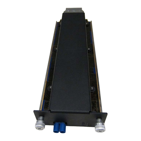
Figure 1. MDS SDM4-1 Data Transceiver
1.1 About This Guide
This guide covers SDM4-1 transceivers operating in
x710-Compatible Mode. All GE MDS manuals are
available free of charge at www.gemds.com.
Invisipbllhaeoc led er
2.0 INSTALLATION
There are three main requirements for installing the
transceiver:
• Adequate and stable primary power
• An efficient and properly installed antenna system
• Correct interface connections between the
transceiver and the data device.
(Figure
1) is a
MDS SDM4‐1
Quick Start Guide (x790 Mode)
Figure 2
shows a chassis with card cage and
backplane that this module would be typically installed
in. The backplane provides the 24V power
connection to this unit and provides the customer data
interfaces through the card edge connector on the
rear of the SDM4-1.
Figure 2: Typical Orbit MPRS Master Station
Chassis. The SDM4-1 modules may be installed in
any free peripheral slot of this chassis.
Figure 3
shows a typical installation of the radio.
NOTE: Retrofit Kits are available to simplify
installation at former MDS x710 digital and analog
sites. Consult the Reference Manual for ordering
details.
Figure 3: Typical Master Station Chassis with
SDM4-1 radio card installed. NOTE: Chassis has
antenna connection in rear, with power and data
connections in the front.
2.1 Installation Steps
1. Install the transceiver into chassis as shown in
Figure 2.
NOTE: To prevent damage to the SDM4-1 radio,
wear a wrist strap to prevent ESD discharge to the
card edge connector. Also, dress all cables as
required to prevent moisture from running along the
cables and into the radio.
Advertisement

Related Manuals for GE MDS SDM4-1


Summary of Contents for GE MDS SDM4-1
- Page 1 MDS x710 digital and analog sites. Consult the Reference Manual for ordering details. Invisipbllhaeoc led er Figure 1. MDS SDM4-1 Data Transceiver Figure 3: Typical Master Station Chassis with SDM4-1 radio card installed. NOTE: Chassis has 1.1 About This Guide...
-
Page 2: Software Configuration
MDS SDM4‐1 Quick Start Guide (x790 Mode) 2. Install the antenna and feedline. The antenna • For Telnet, connect to the radio with a PC used with the radio must be designed to operate in that is on the same IP network as the the radio’s frequency band, and be mounted in a transceiver. -
Page 3: Troubleshooting
MDS SDM4‐1 Quick Start Guide (x790 Mode) a degree of “fade margin.” Optimize the RSSI at 2.2.1 LED Functions Remotes by slowly adjusting the direction of the station antenna. Watch the RSSI indication for several Power seconds after making each adjustment so that the (Green) ... -
Page 4: Command Overview
MDS SDM4‐1 Quick Start Guide (x790 Mode) 4.0 COMMAND OVERVIEW SNR Signal-to-Noise Ratio, expressed in dB SPECTRUM [xxx.xx] Display the transceiver’s built-in Table 3 lists key software commands for the transceiver. spectrum analyzer, where xxx.xx denotes center Detailed descriptions are provided in the SD Reference frequency. - Page 5 MDS SDM4‐1 Quick Start Guide (x790 Mode) (1) this device may not cause harmful interference, and (2) this device must accept any interference received; including interference that may cause undesired operation RF Exposure Notice To comply with RF exposure requirements, the antenna shall Canada, IC ERP Limits be installed to ensure a minimum separation distance shown IC SRSP-501, 6.3.2.