Advertisement
Quick Links
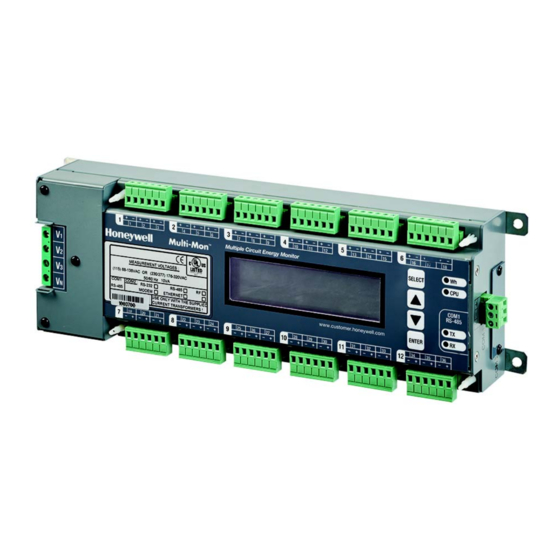
Multi-Mon
MULTIPLE CIRCUIT ENERGY MONITOR
SECTION 1:
GENERAL INFORMATION
The Multi-Mon is a 3-phase, multi-channel, multi-function
energy meter suitable for use in single-phase and multi-phase
electrical networks.
Meter highlights
• Multi-channel submetering – up to 36 single-phase or 18
two-phase or 12 three-phase submeters in a single device.
Any combination of single-, two-, and three-phase
consumers can be chosen up to a total of 36 current inputs.
• Automatic totalization energy from different sub-consumers
INSTALLATION INSTRUCTIONS
FEATURES
• Calibrated to meet Class 0.5S active energy and Class 1
reactive energy meter accuracy
• 3-phase/2-phase/single-phase meters (true RMS, volts,
amps, power, power factor, neutral current)
• Ampere/Volt demand meter
• Time-of-Use, 4 energy/demand registers x 6 tariffs1, 4
seasons x 4 types of days, 8 tariff changes per day, easy
programmable tariff schedule
• Import/export energy and power demands
• Automatic 120–day daily profile for import/export2 energy
and maximum demand readings (total and tariff registers)
separate for each submeter
• Event recorder for logging internal diagnostic events and
setpoint operations
• Data recorders; programmable periodical data logs
separate for each submeter
• Embedded programmable controller (4 control setpoints,
programmable thresholds and delays) separate for each
submeter
• Easy to read 2-row x 16 characters LCD display with
backlight (Multi-Mon only)
•
50/60 Hz operation
•
Internal clock, keeping the clock running over one week
without external power
• Highly Accurate Current Transformer with overvoltage
protection diodes to avoid any damage while disconnecting
the primary current sensor
• Standard RS-485 serial port
• Optional second communication port. Communication
options available:
—
RS-232
—
RS-422/485
—
56K Dial-up modem
—
Ethernet 10/100BaseT
• Modbus RTU and Modbus ASCII communication protocols
• Easy field upgrading device firmware through any
communication port
31-00035-01
Advertisement

Related Manuals for Honeywell Multi-Mon


Summary of Contents for Honeywell Multi-Mon
- Page 1 • Embedded programmable controller (4 control setpoints, programmable thresholds and delays) separate for each The Multi-Mon is a 3-phase, multi-channel, multi-function submeter energy meter suitable for use in single-phase and multi-phase • Easy to read 2-row x 16 characters LCD display with electrical networks.
- Page 2 MULTI-MON THIS PACKAGE CONTAINS Designator Label Sets Multi-Mon HACS DESIGNATOR LABEL SET - TO ATTACH TO THE HACS Highly Accurate Current Sensors (HACS), according to your request. CABLE DESIGNATOR TIE-MARKER HACS - 100A – (solid core) Internal Hole 12 mm (0.47")
- Page 3 To prevent potential fire or shock hazard, do not expose the instrument to rain or moisture. While installing Multi-Mon CTs to the secondary of an external third party current transformer, the external current transformer secondary output must never be allowed to be open circuit when the primary is energized. An open circuit can cause high voltages, possibly resulting in equipment damage, fire and even serious or fatal injury.
- Page 4 MULTI-MON SECTION 2: INSTALLATION Mechanical Installation 5-1/16 (129) 2-13/32 (61) 4-35/64 (116) 21/32 (17) Ø7/32 13-3/64 (331) 11-19/64 11-31/32 (287) (304) 17/32 (14) 2-9/32 (58) 13/32 27/64 (10) (11) 49/64 (20) 4-1/4 (108) M35317 Fig. 3. Multi-Mon dimensions. 31-00035—01...
- Page 5 MULTI-MON M35318 Fig. 4. Wall mounting. M35319 Fig. 5. DIN rail mounting. 31-00035—01...
- Page 6 Fig. 6. Single HACS dimensions. Electrical Installation Multi-Mon offers maximum flexibility of current connections by using the variety of Highly Accurate Current Transformer (HACS) options and by wiring any Highly Accurate Current Transformer to any current input of the device. The following drawings present applications serviced by the Multi-Mon.
- Page 7 MULTI-MON LINE ....HACS2 HACS17 LOAD 1 LOAD 6 HACS3 HACS1 HACS16 HACS18 HACS21 HACS36 HACS19 HACS34 ....LOAD 7 LOAD 12 HACS20 HACS35 M35321 Fig. 8. Typical electrical installation - Delta wiring. HACS (SPLIT CORE) STICKERS TO HACS HACS (SOLID CORE) BLACK –...
- Page 8 The properly marked external 3-pole disconnect device with circuit-breaker and a fuse 6 A, 600 V in every pole should be CTs stickers I1 through I36 correspond to the Multi-Mon installed between voltage measurement terminals and power current inputs with matching labels. Cable stickers 1 through...
- Page 9 MULTI-MON Communications Several communications options are available for the Multi-Mon. RS485 RS485 RS485 RS232 NONE RS485 RS485 RS485 DIAL-UP MODEM TELEPHON ETHERNET RS485/422 M35323 Fig. 11. Communication options. UP TO 31 (PLC) – DEVICES RS-485 M35324 Fig. 12. RS-485 2-wire connection.
- Page 10 MULTI-MON RS-422 COMMUNICATION PORT 4 WIRE CONNECTION TO COMMUNICATION SYSTEM M35326 Fig. 14. RS-422/485 4-wire connection. 1 2 3 4 M35327 Fig. 15. RS-232 connection. COMPUTER CONNECTIONS RS-232 MULTI-MON MULTI-MON IBM PC/COMPATIBLE IBM PC/COMPATIBLE RS232 RS232 25-PIN DB25 9-PIN DB9 MALE CON.
- Page 11 MULTI-MON MODEM CONNECTION M35329 Fig. 17. Modem connection. ETHERNET CONNECTION RS485 ETHERNET M35330 Fig. 18. Ethernet connection. Controls and Indicators VOLTAGES AND HACS CONNECTOR POWER SUPPLY WALL MOUNT TAB TERMINAL ENERGY PULSE LED CPU STATUS COM1 CONNECTOR COM1 INDICATIONS GROUND POST...
- Page 12 LED pulse rate and a submeter for testing. SM 1 FRONT PANEL DISPLAY SM 2 The Multi-Mon is provided with an LCD display and four push … buttons that are used for local meter reading and setup. See Multi-Mon Display Operations in Section 3 for information on...
- Page 13 BACKLIGHT the device diagnostics. In the event of a time fault, update the If no buttons are pressed for 1 minute, the Multi-Mon turns the device clock. In the event of a configuration reset, check the backlight off. To restore the backlight, press any button briefly.
- Page 14 MULTI-MON pressing the ENTER button. Scroll through the display pages within the selected mode by briefly pressing the UP and DOWN buttons. Summary/TOU Energy Page # Page content Description Reg.1 kWh Real Time Measurements Trf.1 32.535 Tariff 1 Page Reg.1 kWh...
- Page 15 MULTI-MON Summary/TOU Max. Demands Total Energy and Maximum Demand Registers Page Page # Page content Description Page content Description Total kWh Total kWh Reg.1 MD kW KW maximum demand 124100.0 Trf.1 32.535 Tariff 1 Total kvarh Total kvarh Reg.1 MD kW KW maximum demand 124.0...
- Page 16 SELECT button. diagnostic codes and their meanings. See Device Diagnostics in Section 2 for more information on the Multi-Mon built-in When the number is set to a desired value, press briefly the diagnostics. See Reset in Section 3 on how to clear the device ENTER button to store your new setting.
- Page 17 MULTI-MON Viewing and Changing Setup Items A second level menu normally consists of three items: the upper-left static item indicates the menu name, while the upper-right item represents a list of setup parameters you can scroll through, and the lower item shows the present parameter value.
- Page 18 MULTI-MON MENU OPERATIONS Submeter Channel Assignments This menu allows you to link the device current terminals to submeters so they can monitor them. Additionally, the menu allows you to specify the primary current rating of the current transformers connected to the device terminals. The number of the selected current inputs for a submeter specifies if it will be a single-, two-, or three-phase meter.
- Page 19 MULTI-MON Reset This menu allows you to reset maximum demands in each submeter and to clear the device diagnostics. To enter the menu, select the Reset entry from the main menu, and then press the ENTER button. To reset the desired registers: 1.
- Page 20 MULTI-MON Basic Device Settings This menu allows you to define the general characteristics of the electrical network. To enter the menu, select the Basic entry from the main menu, and then press the ENTER button. For instructions on navigating in the menu, see Viewing and Changing Setup Items.
- Page 21 NOTE: When using the ExpertPower client (see Configuring eXpertPower Client), submeter address 99 on the Ethernet port COM2 is reserved for the Multi-Mon router and must not fall inside the range of the submeter addresses for this port. 31-00035—01...
- Page 22 Daylight saving standard time only. When enabled, the time (DST) Disabled, Enabled Disabled option Multi-Mon will automatically update the time at 2:00 AM at the pre-defined DST switch dates. DST Mon DST start January- The date when Daylight Saving Time begins.
- Page 23 Display Settings This menu allows you to configure options for the Multi-Mon display. To enter the menu, select the Display entry from the main menu, and then press the ENTER button. For instructions on navigating in the menu, see Viewing and Changing Setup Items.
- Page 24 Type a site name for the submeter in the “File name” box, click New, and then click OK. 3. On the Instrument Setup tab, select Multi-Mon in the “Model” box. Power Software automatically selects the appropriate instrument options for the submeter.
- Page 25 2. Specify the baud rate and data format for the port. Choose the same baud rate and data format as you have set in the Multi-Mon, and then click OK. The default settings for the local RS-232 and RS-422/485 serial ports are 19200 baud, 8 bits with no parity.
- Page 26 Preparing Setups Power Software allows you to prepare setup data for your Multi-Mon off-line without the need to have it connected to your PC. Select the appropriate site from the list box on the Power Software toolbar, and then select the desired setup group from the Meter Setup menu.
- Page 27 Enter the password and click OK. If your authorization was successful, you are not prompted for the password again until you close the dialog window. Changing Port Settings This section describes how to configure communication ports in the Multi-Mon through Power Software. The communication settings affect all submeters in your device. Setting Up Communication Ports To enter the setup dialog, select the site from the list box on the Power Software toolbar, select Communications Setup from the Meter Setup menu, and then click on the Serial Ports Setup tab.
- Page 28 Communication Ports in Section 3. NOTE: When using the ExpertPower client (see Configuring eXpertPower Client), submeter address 99 on the Ethernet port COM2 is reserved for the Multi-Mon router and must not fall inside the range of the submeter addresses for this port.
- Page 29 Do not change the connection period setting. The eXpertPower server updates it automatically. General Meter Setup This section describes how to configure the Multi-Mon for your particular environment and application using Power Software. Basic Meter Setup Before operating your meter, provide the device with basic information about your electrical network.
- Page 30 MULTI-MON Fig. 27. The following table lists available device configuration options. Parameter Options Default Description Basic Configuration The phase potential transformer’s primary to secondary ratio PT Ratio 1.0-6500.0 The CT primary current of the submeter’s; for information only. Primary current...
- Page 31 MULTI-MON Parameter Options Default Description 5.40 Wh/pulse Energy LED pulse LED pulse constant - the amount of accumulated energy (in 0.01-100.00 (one equivalent rate, Wh/pulse secondary readings) giving one pulse via “Wh”. disk revolution) Disabled, Energy LED Test Wh Pulses, Disabled The type of accumulated energy giving pulses via “Wh”...
- Page 32 Transformer Correction Transformer correction allows you to compensate ratio and phase angle inaccuracies of the user voltage transformers and Multi-Mon CTs. To enter the setup dialog, select the device site from the list box on the Power Software toolbar, and then select Transformer Correction from the Meter Setup menu.
- Page 33 MULTI-MON Fig. 29. The following table lists available options. Parameter Options Default Description Ratio Correction Factor 0.700 to 1.300 1.000 The ratio of the true transformer ratio to the marked ratio. The phase displacement, in minutes, between the primary and secondary Phase Angle Error, values.
- Page 34 Last (last week of the month) When the daylight saving time is enabled, the Multi-Mon automatically adjusts the device clock at 02.00 AM when daylight saving time begins/ends. The default daylight saving time change points are set for the U.S.A.
- Page 35 Multi-Mon has an embedded logical controller that runs different actions in response to user-defined internal and external events. Unlike a PLC, the Multi-Mon uses a simplified programming technique based on setpoints that allows the user to program a required action based on a measured analog value or on a time. The controller provides up to 4 setpoints for each submeter.
- Page 36 MULTI-MON Using Time Triggers If you want the setpoint actions to be synchronized with the clock, for example, to provide recording interval data, use the minute time interval trigger that generates periodic events synchronized with the device clock. Delaying Setpoint Operations Two optional delays can be added to each setpoint to extend monitoring a setpoint trigger for a longer time before making a decision on whether the expected event occurred or not.
- Page 37 MULTI-MON CONFIGURING BILLING ENERGY AND TOU REGISTERS The Multi-Mon provides four total/summary energy and six parallel tariff energy and maximum demand registers for each individual submeter. The registers can be linked to any internal energy source or to another submeter.
- Page 38 MULTI-MON Parameter Options Default Description Billing/TOU Registers Unchecked Links tariff registers to the selected energy source Unchecked Checked Enables automatic daily profiling for energy usage registers (both total and tariff Unchecked Use Profl Unchecked registers if TOU is enabled) Checked...
- Page 39 The first tariff change point is fixed at 00:00 hours, and the last tariff change you specified will be in use until 00:00 hours on the next day. The energy daily profile log will be automatically configured for the number of active tariffs you defined in the Multi-Mon TOU daily profile.
- Page 40 Configuring Data Recorders The Multi-Mon provides a separate Data recorder for each metering submeter. The recorder is triggered via a setpoint periodically for recording interval data (see Using Alarm/Control Setpoints). The device memory is factory partitioned to allow recording one data log file per submeter (Data Log #1) with a maximum of 5000 records per file.
- Page 41 Section 2 for more information on the Multi-Mon built-in diagnostics. Click on the Clear button to clear the device diagnostics. You must be connected to the Multi-Mon using the device base address to be able to clear the diagnostics status.
- Page 42 MULTI-MON Fig. 36. Updating the Clock To update the RTC clock in your device, select a site with base device address from the list box on the toolbar, check the On-line button on the toolbar, and then select RTC from the Monitor menu.
- Page 43 Fig. 38. Administration Power Software allows you to remotely change the password or network security in your Multi-Mon. Use the device base address to access your device. To change the password, select a device site from the list box on the Power Software toolbar, check the On-line button, click Administration from the monitor menu, and then select Change Password.
- Page 44 3. Check the On-line button on the Power Software toolbar, select Flash Downloader from the Monitor menu, and then confirm changes. Fig. 40. 4. Point to the firmware upgrade file for your Multi-Mon, click Open, and then confirm upgrading the device. You would be asked for the password regardless of the password protection setting in your Multi-Mon. Fig. 41.
- Page 45 Any energy and maximum demand registers in the Multi-Mon submeters can be read and recorded to files through the Power Software Data Monitor. Retrieving Log Files Using Power Software, you can retrieve the event and data log files from the Multi-Mon submeters and save them to files on your PC in the MS Access database format. 31-00035—01...
- Page 46 Getting Started Guide. RETRIEVING THE EVENT LOG The Multi-Mon provides a separate Event log file for each metering submeter. All general device events, like device diagnostics, are recorded to the first Event log file that is accessed via the device base address.
- Page 47 MULTI-MON The following picture shows an example of energy profile data readings. Fig. 46. 31-00035—01...
- Page 48 MULTI-MON APPENDIX A: TECHNICAL SPECIFICATIONS Environmental Conditions Indoor use only BFM is intended for operation in environment where normally only nonconductive pollution occurs as defined for pollution degree 2 (UL61010, 3.6.6.2) Communication Ports Operating Temperature: -40 to 70 °C (-40 to 158°F) Storage Temperature: -40 to 80 °C (-40 to 176 °F)
- Page 49 MULTI-MON Measurement Specifications Accuracy Full Scale @ Input Parameter Range % Reading % FS Conditions Range Voltage = 230V 184 to 260 V 0 to Vmax= 600 V 0.05 Line current Instrument current 1 to 100% FS 0 to CT primary current transformer CTs Starting current: 0.1% FS...
- Page 50 MULTI-MON APPENDIX B: CT CONNECTION TEMPLATE Use the following table to memorize your input assignments and wiring connections for sub-consumers. Sub-consumer Input# Wire Color Cable# Phase #1 through #36 31-00035—01...
- Page 51 MULTI-MON APPENDIX C: PARAMETERS FOR DATA MONITORING AND LOGGING The following table lists parameters measured by the meter that are available for data logging and monitoring through communications. The left column shows data abbreviations used in Power Software. Parameter groups are highlighted in bold.
- Page 52 MULTI-MON Designation Description V3 Voltage I1 Current I2 Current I3 Current kW L1 kW L1 kW L2 kW L2 kW L3 kW L3 kvar L1 kvar L1 kvar L2 kvar L2 kvar L3 kvar L3 kVA L1 kVA L1 kVA L2...
- Page 53 MULTI-MON Designation Description kW EXP ACC DMD kW export accumulated demand kvar IMP ACC DMD kvar import accumulated demand kvar EXP ACC DMD kvar export accumulated demand kVA ACC DMD kVA accumulated demand kW IMP PRD DMD kW import predicted sliding window demand...
- Page 54 MULTI-MON Designation Description ACTIVE TARIFF Active TOU tariff ACTIVE PROFILE Active TOU profile TOU REG1 TOU Energy Register #1 TOU REG1 TRF1 Tariff #1 register TOU REG1 TRF2 Tariff #2 register TOU REG1 TRF3 Tariff #3 register TOU REG1 TRF4...
- Page 55 MULTI-MON Designation Description DMD3 TRF1 MAX Tariff #1 register DMD3 TRF2 MAX Tariff #2 register DMD3 TRF3 MAX Tariff #3 register DMD3 TRF4 MAX Tariff #4 register DMD3 TRF5 MAX Tariff #5 register DMD3 TRF6 MAX Tariff #6 register TOU MAX DMD REG4...
- Page 56 MULTI-MON APPENDIX D: SETPOINT TRIGGERS AND ACTIONS Setpoint Triggers Setpoint Actions Designation Description Designation Description NONE None (condition is not active) NONE None (no action) MINUTE INTERVAL Minute intervals (10, 15, 30, 60 min) EVENT LOG Log to Event Log...
- Page 57 DATA SCALES The maximum values for volts, amps and power in the Multi-Mon setup and in communications are limited by the voltage and current scale settings. See Basic Meter Setup in Section 4 on how to change the voltage scale in your meter.
- Page 58 MULTI-MON APPENDIX F: DEVICE DIAGNOSTIC CODES See Device Diagnostics in Section 2 for more information on the Multi-Mon built-in diagnostics. Startup Display Diagnostic Code Message Description Reason RAM/Data Error Memory/Data error Hardware failure WDT Reset Hardware watchdog reset Hardware failure...
- Page 59 MULTI-MON 31-00035—01...
- Page 60 MULTI-MON By using this Honeywell literature, you agree that Honeywell will have no liability for any damages arising out of your use or modification to, the literature. You will defend and indemnify Honeywell, its affiliates and subsidiaries, from and against any liability, cost, or damages, including attorneys’...