Table of Contents
Advertisement
Advertisement
Table of Contents

Related Manuals for Honeywell MeshGuard FTD-2000


Summary of Contents for Honeywell MeshGuard FTD-2000
- Page 1 MeshGuard Monitor User’s Guide Rev. K January 2019 P/N D01-4002-000...
- Page 2 © Copyright 2019 RAE Systems by Honeywell.
-
Page 3: Table Of Contents
MeshGuard User’s Guide Contents 1 Standard Kit ................................ 6 2 General Information ............................6 3 Physical Description ............................8 LCD Display............................9 Specifications ............................ 10 4 Operating The MeshGuard ..........................11 Turning The MeshGuard On ......................11 Turning The MeshGuard Off ......................12 Low Battery Indicator &... - Page 4 • Calibration intervals and bump test procedures may vary due to national legislation. • Honeywell recommends using calibration gas cylinders containing the gas that is appropriate to the sensor you are using, and in the correct concentration.
- Page 5 MeshGuard User’s Guide WARNINGS Read Before Operating This manual must be carefully read by all individuals who have or will have the responsibility of using, maintaining, or servicing this product. The product will perform as designed only if it is used, maintained, and serviced in accordance with the manufacturer’s instructions.
-
Page 6: Standard Kit
MeshGuard User’s Guide Standard Kit Monitor with antenna User’s Guide CD with resources Maintenance tool Calibration certificate Calibration adapter General Information MeshGuard (FTD-2000) is a single toxic gas detector integrated with a wireless mesh network-enabled transmission radio module. It can work as a fixed device or as a portable device. The detector has the option of relaying the wireless signal to other MeshGuards as needed, to bypass obstacles. - Page 7 MeshGuard User’s Guide Key Features Up to 6 months continuous operation IEEE 802.15.4 Mesh network functionality with 64-bit encryption Robust wireless mesh network with auto network forming and configuration Operating distance: up to 300 m (985 ft), line of sight ...
-
Page 8: Physical Description
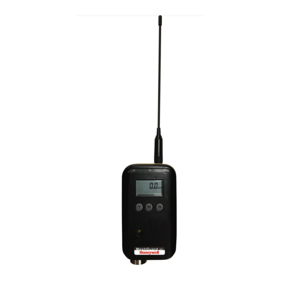
MeshGuard User’s Guide Physical Description Note: The physical appearance of the MeshGuard is virtually identical, whether in a metal enclosure or a plastic enclosure. Functionality is identical, regardless of the enclosure. LED alarm LCD (with backlighting) Buzzer alarm Sensor gas inlet Battery cover (on bottom) Y/+, MODE, and N/- keys Antenna... -
Page 9: Lcd Display
MeshGuard User’s Guide 3.1 LCD Display Zero Calibration Low Battery Indicator Wireless Communication (if on, the monitor is in STD; if blinking, the monitor is RTR) Short Term Exposure Limit (STEL) Time Weighted Average (TWA) 6, 8* High Alarm 7, 8* Low Alarm Gas Concentration unit, ppm Gas Concentration unit, %... -
Page 10: Specifications
CE EN 300328 SRRC (Pending) Wireless Approval For UAE In Middle East (TRA REGISTERED No: ER36063/14 DEALER No: HONEYWELL INTERNATIONAL MIDDLE EAST - LTD - DUBAI BR Wireless Approval for QATAR In Middle East ictQATAR Type Approval Reg. No.: R-4465 Display Customized LCD (1 x 1.5″) with backlight... -
Page 11: Operating The Meshguard
MeshGuard User’s Guide Operation Operating The MeshGuard Make sure the battery is installed before operating the MeshGuard. Refer to page 34 for information on battery installation and replacement. 4.1 Turning The MeshGuard On Hold down the [MODE] key and release it when the MeshGuard beeps. The monitor is now on, as indicated by the display: The MeshGuard performs a self-test, followed by warm-up and zero calibration. -
Page 12: Turning The Meshguard Off
MeshGuard User’s Guide Next, the display tells you that MeshGuard is initiating network communication: Next, if a network is located, an antenna icon appears (if no network is found, then refer to “Join Mesh Network” on page 27). The current gas concentration reading is also displayed: Note: When adding a MeshGuard detector to a new network for the first time, it is recommended that you press [Y/+] to manually initiate a search for the network. -
Page 13: Wireless Communication Indicator
MeshGuard User’s Guide 4.4 Wireless Communication Indicator When wireless communication is turned on, the LCD displays the wireless link status in the upper left corner: If the MeshGuard finds and joins a wireless network, an antenna icon is shown in the display. If no link or a weak link is established, no antenna icon is shown. -
Page 14: Detection Mode
MeshGuard User’s Guide 5.1 Detection Mode The MeshGuard can operate in fixed or portable mode. Whenever you start MeshGuard, it is automatically in fixed Detection Mode, which is the default. The MeshGuard displays the current reading: Pressing [MODE] steps through the Detection Mode screens: Press [MODE], and it displays the sensor type: Press [MODE], and it alternates between EUI (Extended Unique Identifier) and its value: Press [MODE], and it alternates between Pan and ID (Personal Area Network Identifier) and its value:... -
Page 15: Manually Sending Data
MeshGuard User’s Guide 5.2 Manually Sending Data While the MeshGuard typically sends reading data to the network on a fixed interval, you can send the data anytime. When the monitor is connected to the network, press the [Y/+] key. The screen displays “Ini” and “nEt” one time, and the monitor sends the current sensor data, and returns to the detector reading. - Page 16 MeshGuard User’s Guide Press [MODE], and it displays TWA. The TWA (time-weighted average) is the accumulated reading of the gas concentration, divided by 8 hours, since the monitor was turned on. Press [MODE], and the display indicates the Peak reading by alternating between “P” (for “Peak”) and a numerical value: Press [MODE] to return to the current reading:...
-
Page 17: Programming Mode
MeshGuard User’s Guide 5.4 Programming Mode Programming Mode allows you to perform any of the following actions (listed in order of appearance): • Calibrate the MeshGuard • Changing Preset Limits or Span Gas Values • Set Pan ID • Join network •... -
Page 18: Entering Programming Mode
MeshGuard User’s Guide 5.4.1 Entering Programming Mode To enter the Programming Mode, press [MODE] and [N/-] for 3 seconds. “Pro” appears in the display: Pressing [N/-] steps you through all the screens and then returns to the first programming display: Each display alternates between its name and a status message or value. -
Page 19: Exiting Programming Mode
MeshGuard User’s Guide Settings can be changed as follows: 1. When a menu is selected, it flashes between two screens. For example: 2. Press [MODE] to exit Program Mode and return to Detection Mode, or press [N/-] to advance to the next menu. 3. -
Page 20: Span Calibration
MeshGuard User’s Guide The display counts down from 10 to 0. After the countdown reaches 0, the LCD displays “dn,” for “done.” The reading should show 0 (zero). Otherwise, repeat the zero calibration. Note: To stop zero calibration before the countdown reaches 0, press any key. The LCD displays “no” and advances to the next programming menu, Span calibration. - Page 21 MeshGuard User’s Guide When the gas flow starts, the LCD displays “gAS” and the span concentration value. The MeshGuard now counts down to 0. Note: The countdown time varies according to the type of sensor used in the MeshGuard. After counting down and reaching 0, the LCD displays “dn.” The reading should be the span concentration value. Otherwise, the span calibration should be repeated.
-
Page 22: Change High Alarm
MeshGuard User’s Guide 5.4.5 Change High Alarm At the menu for changing the High Alarm setting, “ Set” and “ go” flash in alternation, and both “HIGH“ and “ALARM” are shown. Note: It is not recommended to increase the High Alarm setting above the factory default value. Note: The High Alarm value varies, depending on different sensor types. -
Page 23: Change Low Alarm
MeshGuard User’s Guide 5.4.6 Change Low Alarm At the Change Low Alarm menu, “Set” and “go” flash in alternation, and “LOW” and “ALARM” are visible in the display. Note: It is not recommended to increase the Low Alarm setting above the factory default value. Note: The Low Alarm value varies by sensor type. -
Page 24: Change Stel Setting (Portable Mode Only)
MeshGuard User’s Guide 5.4.7 Change STEL setting (Portable Mode Only) Note: This menu is only available when the MeshGuard is in Portable Mode. If it is in Fixed Mode, you will not see this menu and cannot change its settings. “Set”... -
Page 25: Change Twa Setting (Portable Mode Only)
MeshGuard User’s Guide 5.4.8 Change TWA setting (Portable Mode Only) Note: This menu is only available when the MeshGuard is in Portable Mode. If it is in Fixed Mode, you will not see this menu and cannot change its settings. “Set”... -
Page 26: Change Span Value
MeshGuard User’s Guide 5.4.9 Change SPAN value “Set” and “go” flash in alternation, and “SPAN” and a gas cylinder icon are shown. Note: The Span value varies, depending on different sensor types. Press [Y/+] to enter and change the setting, [MODE] to exit and return to Detection Mode, or [N/-] to advance to the next menu. -
Page 27: Change Pan Id
MeshGuard User’s Guide 5.4.10 Change Pan ID Press [Y/+] to enter the menu to make changes to the value. 1. Press [Y/+] to increase the number and [N/-] to decrease it. 2. Press [MODE] to advance to the next digit. 3. -
Page 28: Diagnostic Mode
MeshGuard User’s Guide Diagnostic Mode Diagnostic Mode provides raw data from sensors and about settings. 6.1 Entering Diagnostic Mode Note: To enter Diagnostic Mode, you must begin with the MeshGuard turned off. Press and hold [Y/+] and [MODE] until the MeshGuard starts. The instrument goes through a brief startup, and then displays “dIA”... -
Page 29: Diagnostic Mode Readings
MeshGuard User’s Guide 6.3 Diagnostic Mode Readings In Diagnostic mode, you can step through readings by pressing [N/-]. 6.3.1 Sensor Raw Count Sensor Raw Count is indicated by “rAU” followed by a number. Press [N/-] to advance to the next reading. •... -
Page 30: Calibration Delta Counts
MeshGuard User’s Guide 6.3.5 Calibration Delta Counts Calibration Delta CTS is indicated by “CdC” followed by a number. • Press [N/-] to return to the first raw count. 6.4 Diagnostic Mode Programming You can enter a special programming mode from Diagnostic Mode in order to perform advanced programming functions. - Page 31 MeshGuard User’s Guide Enter this programming mode by first entering Diagnostic Mode. Refer to “Entering Diagnostic Mode,” page 30. Step through the menus by pressing [N/-]. Exit by pressing [MODE], and then shutting off the MeshGuard and restarting it.
-
Page 32: Fixed Or Portable Operation Selection
MeshGuard User’s Guide 6.4.1 Fixed Or Portable Operation Selection The first menu is for setting the MeshGuard for fixed or portable operation. In Portable Mode, STEL, TWA, and Peak readings are included. “SEt” and “ Ptb” flash in alternation, to indicate that the MeshGuard can now be set as fixed or portable. The default value is “fixed.”... -
Page 33: Factory Setting
MeshGuard User’s Guide 6.4.4 Factory Setting Press [Y/+] to return the MeshGuard to its original factory settings. Note: This function clears all custom settings and returns all settings their factory default values. This cannot be undone. 6.4.5 Audible & Visible Alarm Enable/Disable Press [Y/+] to toggle between the MeshGuard’s audible and visible alarms turned on and off. -
Page 34: Sensor And Battery Replacement
MeshGuard User’s Guide Sensor And Battery Replacement Sensor compartment Battery compartment Sensor and battery 3-pin end removal tool (P/N 019-2044-000) Hexagonal end 7.1 Battery replacement 1. Use the 3-pin end of the tool to unscrew and open the battery cover by turning it counterclockwise. 2. -
Page 35: Sensor Filter Replacement
MeshGuard User’s Guide 7.2 Sensor Filter Replacement Use the 3-pin end of the tool to unscrew and open the filter holder by turning it counterclockwise. Remove and discard the filter. Place a new filter inside the monitor. Replace the filter holder by turning it clockwise with the 3-pin end of the tool. Filter Filter holder... -
Page 36: Sensor Replacement
MeshGuard User’s Guide 7.3 Sensor Replacement 1. Use the 3-pin end of the tool to unscrew and open the filter holder at the bottom of the monitor. Sensor Sensor cover Filter Filter holder 2. Use the hexagonal end of the tool to open the remove the sensor cover, turning counterclockwise. 3. -
Page 37: Troubleshooting
MeshGuard User’s Guide Troubleshooting Failure Symptom Cause Solution Cannot turn on Battery charge too low Replace battery Battery has been Wait at least 60 changed seconds to turn on MeshGuard New battery needs to Check RAE Systems be discharged before web site for inform- ation on batteries Abnormally high... -
Page 38: Alarm Signal Summary
MeshGuard User’s Guide Alarm Signal Summary Alarm When Buzzer & LED Mode 3 beeps per second Gas readings exceed the Over Range maximum value of the sensor 3 beeps per second > high alarm High Alarm setting 2 beeps per second >... -
Page 39: Appendix A: Installation
MeshGuard User’s Guide Appendix A: Installation Two methods for mounting MeshGuard make it easy to install. The first method uses a magnet that screw onto the rear of the MeshGuard, making ideal for moving from one location to another. The second method uses a specially designed stainless-steel enclosure that is permanently mounted. -
Page 40: Fixed Installation
MeshGuard User’s Guide 10.2 Fixed Installation Four reinforced holes in the rear of the enclosure allow for a screw to pass through to the mounting brackets. Mounting Holes Side Front View View Sensor Cover The enclosure can be mounted to a vertical or horizontal pole. Vertical pole Horizontal pole... - Page 41 MeshGuard User’s Guide Slip the screws through the two holes that are side by side in order to mount the enclosure to a vertical pole. Otherwise slip the screws through the two vertically aligned holes to attach the enclosure to a horizontal pole. Loosely assemble the clamp parts around the pole.
- Page 42 MeshGuard User’s Guide Next, place the MeshGuard into the enclosure: 1. Lift up the hinged cover of the enclosure. 2. Slide the MeshGuard into the enclosure from the top. 3. Close the cover of the enclosure. 4. Insert the hex screw into the cover’s locking portion, and tighten it. 5.
-
Page 43: Magnetic Mount Alternative Installation
MeshGuard User’s Guide 10.3 Magnetic Mount Alternative Installation The magnet-mount disc can be attached to the steel enclosure instead of the clamps. This approach provides the protection of the enclosure with the ease of installation afforded by the magnetic mounting. 1. -
Page 44: Meshguard Sensor Specifications
MeshGuard User’s Guide MeshGuard Sensor Specifications Sensor Normal Resolution Response Temperature Range Time Range 0 to100 ppm 0.1 ppm < 30 sec -20° C to +50° C < 30 sec (-4° F to 122° F) 0 to1000 ppm 1 ppm <... - Page 45 MeshGuard User’s Guide To identify the year of manufacture, refer to the serial number of the instrument. The letter in the serial number indicates the year of manufacture. For example, “M” indicates the manufacturing year is 2010. Letter Year 2018 2019 2020 2021...
- Page 46 For more information www.raesystems.com D01-4002-000 Rev K January 2019 © 2019 Honeywell International...