Table of Contents
Advertisement
Quick Links
LCD-SLP
Liquid Crystal Display-Smart Loop Panel
Product Installation Document
CAUTION 1: STATIC SENSITIVE EQUIPMENT:
!
THIS EQUIPMENT IS SENSITIVE TO STATIC ELECTRICITY. IT MAY BE DAMAGED IF NOT PROPERLY HANDLED.
TRANSPORT AND STORE THIS UNIT IN A STATIC-SHIELDING BAG.
FAILURE TO OBSERVE THIS REQUIREMENT COULD CAUSE LATENT DAMAGE TO THE EQUIPMENT WHICH
MIGHT NOT MANIFEST ITSELF UNTIL AFTER THE EQUIPMENT IS PLACED IN SERVICE.
CAUTION 2: DISCONNECT ALL POWER:
!
REMOVE ALL SOURCES OF POWER BEFORE SERVICING, REMOVING OR INSTALLING ANY UNITS.
Section 1: Description
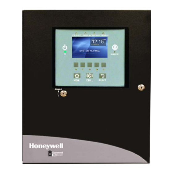
The LCD-SLP (Liquid Crystal Display-Smart Loop Panel) is a 4.3"(10.92 cm) diagonal, 480 x 272 pixels, color touchscreen
interface that consists of system events including indicating LEDs and control switches. It may be remotely located via a local RS-
485 serial interface. The LCD-SLP display is a remote annunciator that is compatible with the following system, modules.
• S3 Series, SLP-E3
(Smart Loop Panel-Main Board)
The SLP-E3, ILI-MB-E3 and ILI95-MB-E3 modules support up to 15 fully-functional and supervised LCD-SLP color touchscreen
interfaces.
NOTE: E3 RELEASING PANEL OPERATOR INTERFACE INSTALLATION REQUIREMENTS:
The LCD-SLP display panel includes optional audio/visual signaling capabilities for the E3 Series Releasing application. The
E3 Releasing application contains an RS-485 circuit to support the connection of up to fifteen LCD-SLP displays. In
CAMWorks, you must configure at least one LCD-SLP as a Releasing panel operator interface.
Firmware Compatibility
Table 1.1 lists the Firmware Compatibility for the LCD-SLP touchscreen..
CAMWorks Firmware
Version
CAMWorks Version
3.40 or later.
For UL 864 10th Edition
compliance, use, use
Firmware Version
3.52 or later.
Figure 1.1 illustrates the LCD-SLP touchscreen.
Document LS10045-000GF-E:E
®
• E3 Series
(Intelligent Loop Interface-Main
ILI-MB-E3
First Generation
Minimum Firmware Version
Firmware Version
3.3 or later.
Water release only.
UL 864 10th Edition Standard
For UL 864 10th Edition
compliance, use
Firmware Version
4.10 or later.
Table 1.1 Firmware Versions
Figure 1.1 LCD-SLP Panel Display
12/16/2019
ECN 19-0583
, ILI-MB-E3
Board)
ILI-MB-E3
Second Generation
Firmware Version
4.3 or later.
For UL 864 10th Edition
compliance, use
Firmware Version
4.10 or later.
• E3 Series, ILI95-MB-E3
(Intelligent Loop Interface95-Main Board)
SLP-E3
Firmware Version
Firmware Version
1.21 or later.
For UL 864 10th Edition
compliance, use
Firmware Version
1.21 or later.
LCD-SLP
Firmware Version
Firmware Version
2.10 or later.
For UL 864 10th Edition
compliance, use
Firmware Version
2.12 or later.
Advertisement
Table of Contents

Related Manuals for Honeywell GAMEWELL LCD-SLP


Summary of Contents for Honeywell GAMEWELL LCD-SLP
- Page 1 LCD-SLP Liquid Crystal Display-Smart Loop Panel Product Installation Document CAUTION 1: STATIC SENSITIVE EQUIPMENT: THIS EQUIPMENT IS SENSITIVE TO STATIC ELECTRICITY. IT MAY BE DAMAGED IF NOT PROPERLY HANDLED. TRANSPORT AND STORE THIS UNIT IN A STATIC-SHIELDING BAG. FAILURE TO OBSERVE THIS REQUIREMENT COULD CAUSE LATENT DAMAGE TO THE EQUIPMENT WHICH MIGHT NOT MANIFEST ITSELF UNTIL AFTER THE EQUIPMENT IS PLACED IN SERVICE.
-
Page 2: Section 1: Installation
Figure 2.8.4.1 Table 2.3.1 LCD-SLP Assembly Installation Options ® E3 Series is a registered trademark and CAMWorks™ is a trademark of Honeywell International Inc. ©2020 Copyright by Honeywell International Inc. All rights reserved. LCD-SLP Product Installation Document — P/N LS10045-000GF-E:E 12/16/2019... -
Page 3: Specifications
2.4 Circuit Ratings and Specifications Table 2.4.1 lists the LCD-SLP circuit ratings and specifications. Specifications LCD-SLP Operating Voltage: +24 VDC Operating Current: 0.030 A Alarm Current: 0.065 A Ground fault test impedance: Zero Ohms Impedance values and ground faults are annunciated: GND Fault LED or LCD-SLP Relative Humidity: 0 to 93%, non-condensing at 90°... - Page 4 2.6 LCD-SLP Installed in an S3 Series, Cabinet Configuration The SLP- BB cabinet is shipped with the LCD-SLP touchscreen pre-assembled to the inner door. To install the LCD-SLP touchscreen to the window space on the outer door or the inner door, refer to the following instructions. 2.6.1 LCD-SLP Installed to the 2.6.2 LCD-SLP Installed to the SLP-BB Cabinet Outer Door...
- Page 5 2.7 LCD-SLP Installed in an E3 Series, Cabinet Configuration The LCD-SLP touchscreen can be installed in the several E3 Cabinets. To install the LCD-SLP touchscreen to the window space on the inner door, refer to the following instructions. 2.7.1 LCD-SLP Installed in E3 Series Cabinet A2 and AA 2.7.1.1 LCD-SLP Installed to the CAB A2 Inner Door Mount the LCD-SLP keypad to the inner door and secure with four, #6-32 nuts in the four-hole mounting pattern as shown in Location 1 of the figure below.
-
Page 6: Inner Door
2.7.1.3 LCD-SLP Installed to the Cabinet AA 2-Bay Inner Door Mount the LCD-SLP keypad to the inner door. Insert and secure eight nuts (#6-32) into the eight-hole mounting pattern as shown in Location 1 of the figure below. NUT, HEX (#6-32) 12 PLACES BONDING... - Page 7 2.7.3 LCD-SLP Installed to a Cabinet 2.7.4 LCD-SLP Installed to a Cabinet C, INCC-E3 7-Bay Inner Door D Inner Door Mount the LCD-SLP keypad to the Cabinet C, INCC-E3, 7- Mount the LCD-SLP keypad to the Cabinet D, 13-bay inner bay inner door.
-
Page 8: Mounting Plate
2.8 LCD-SLP Installation in a Retrofit Cabinet Configuration 2.8.1 LCD-SLP Installed to a B-Slim Cabinet Outer Door Insert the keyswitch to the LCD-E3 Mounting Plate. Insert and secure one nut, (3/4” x 24 THD HEX) as shown in Location 1 of the figure below. - Page 9 2.8.3 LCD-SLP Installed to a 7200 2.8.4 LCD-SLP Installed to a 7200 CAB B Retrofit Inner Door CAB C Retrofit Inner Door Mount the LCD-SLP keypad to the inner door. Insert and Mount the LCD-SLP keypad to the inner door. Insert and secure eight nuts (#6-32) into the eight-hole mounting secure eight nuts (#6-32) into the eight-hole mounting pattern as shown in Location 1 of the figure below.
- Page 10 Section 3: Wiring 3.1 LCD-SLP Wiring Requirements Table 3.1.1 lists the LCD-SLP wiring requirements. Circuit Type Circuit Function Wire Requirements Distance Typical Wire Type RS-485 Connects to the LCD-E3, Twisted-unshielded pair 3,000 ft. 16 AWG (1.30 mm2) (Class 2 Power- LCD-SLP, ASM-16 and with a characteristic (.914 m) (maximum)
- Page 11 NOTES NOTE 1: INPUTS TO LCD-SLP FROM ILI-MB-E3/ILI95-MB-E3: If you do not use J5, these connections are required. Use this terminal designation to connect from the ILI-MB-E3/ ILI95-MB-E3 of the E3 Series panel. NOTE 2: INPUTS TO LCD-SLP FROM THE REMOTE S3 OR E3 SERIES PANELS: Use this terminal designation to connect from remote S3 installations or from the ILI-MB-E3/ILI95-MB-E3 of the E3 Series panel.
-
Page 12: Key Switch
3.2.1 LCD-SLP Wired to the S3 Series Panel Figure 3.2.1.1 illustrates terminal connections of the LCD-SLP touchscreen wired to the S3 Series panel. NON-RESETTABLE 24 VDC POWER IN (+) 24 VDC COMMON IN (-) NON-RESETTABLE 24 VDC POWER OUT (+) 24 VDC COMMON OUT (-) EXTRA GROUND EARTH GROUND... - Page 13 Section 4: LCD-SLP Display Panel 4.1 LCD-SLP Touchscreen LEDs and Switches Figure 4.1.1 illustrates the screen that appears when you program in CAMWorks for Non-Releasing Fire applications. FIR E A LA R M H A ZA R D SU PE R V IS O R Y TR O U B LE A C P O W E R SILEN C E D M ENU...
- Page 14 4.2 LCD-SLP Non-Releasing Zone Screens for Fire Operation Table 4.2.1 lists the LCD-SLP, System Status screens for non-releasing fire operation. System Status Visual Indicator Screens Examples of Event Screens Description Event Activation Displays the System Status Fire If this event is activated, the following Alarm to show a Fire Alarm appears on the display.
- Page 15 Section 5: LCD-SLP Releasing Application The LCD-SLP display panel includes optional audio/visual signaling capabilities for the E3 Series Releasing application. The E3 Releasing application contains an RS-485 circuit to support the connection of up to fifteen LCD-SLP displays. The following five LEDs can be configured to appear on the LCD-SLP display panel to signal the stages of the E3 Series Releasing process.
- Page 16 5.2 LCD-SLP Releasing Zone Screens for Releasing Operation Table 5.2.1 lists the LCD-SLP screens that show the E3 Series Releasing operation on the LCD-SLP display panel. LEDs Display Description Standby When the System is at the Standby stage, the following occurs: FIRE ALARM HAZARD SUPERVISORY TROUBLE •...
-
Page 17: Section 6: Programming Requirements
LEDs Display Description Release If the Releasing Zone is pre-programmed to use the Pre- Release Timer, after the Pre Release time interval, the FIRE ALARM HAZARD SUPERVISORY TROUBLE following occurs. • The Release LED lights steady RED. • Release appears on the display. SILENCED •... -
Page 18: Section 7:Reference Documentation
LS10056-000GF-E S3 Series (Small Addressable Fire Alarm Control Panel System), Operating Instructions LS10121-000GF-E E3 Series for LCD-SLP Operating Instructions Table 7.1 Reference Documentation Honeywell Gamewell-FCI 12 Clintonville Road Northford, CT 06472-1610 203.484.7161 LS10045-000GF-E | E | 06/20 www.gamewell-fci.com ©2020 Honeywell International Inc.