Cisco Catalyst 8300 Series Hardware Installation Manual
Edge platforms
Hide thumbs
Also See for Catalyst 8300 Series:
- Hardware installation manual (46 pages) ,
- Hardware installation manual (48 pages)
Table of Contents
Advertisement
Quick Links
Advertisement
Table of Contents

Related Manuals for Cisco Catalyst 8300 Series


Summary of Contents for Cisco Catalyst 8300 Series
- Page 1 Hardware Installation Guide for Cisco Catalyst 8300 Series Edge Platforms First Published: 2020-10-28 Last Modified: 2020-11-05 Americas Headquarters Cisco Systems, Inc. 170 West Tasman Drive San Jose, CA 95134-1706 http://www.cisco.com Tel: 408 526-4000 800 553-NETS (6387) Fax: 408 527-0883...
- Page 2 Cisco and the Cisco logo are trademarks or registered trademarks of Cisco and/or its affiliates in the U.S. and other countries. To view a list of Cisco trademarks, go to this URL: https://www.cisco.com/c/en/us/about/legal/trademarks.html.
-
Page 3: Table Of Contents
Overview Chassis Views Platform Summary Locating Labels on Cisco Catalyst 8300 Series Edge Platforms Location of labels on Cisco Catalyst 8300 Series Edge Platforms Locate Product Identification Details Hardware Features of Cisco Catalyst 8300 Series Edge Platforms Built-In Interface Ports... - Page 4 Mount the Chassis on a Desktop Rack Mount the Chassis Attach the Rack-Mounting Brackets Mount the Chassis on a Rack Attach Cisco Cisco Catalyst 8300 Series Edge Platforms on a Wall Ground the Chassis Chassis Grounding Connect Power to the Device...
- Page 5 Prepare the Wire for Connecting to the DC Power Supply Remove and Install PoE Converter Power Supply Unit Remove the PoE Power Supply Slot Filler Install the PoE Power Supply Slot Filler Remove the PoE Converter Power Supply Hardware Installation Guide for Cisco Catalyst 8300 Series Edge Platforms...
- Page 6 Contents Install the PoE Converter Power Supply Replace a Fan Tray for Cisco Catalyst 8300 Series Edge Platforms Before Replacing a Fan Tray Replace a Fan Tray in a C8300-2N2S-4T2X|6T Remove the Fan Tray Air Filter from a C8300-2N2S-4T2X|6T Remove the Fan Tray from a C8300-1N1S-4T2X|6T...
- Page 7 RF Band Mapping for Antenna Ports (For P-5GS6-GL only) Attaching the Antennas C H A P T E R 8 Online Insertion and Removal and Hot-Swapping OIR Procedures Remove a Module Insert a Module Hardware Installation Guide for Cisco Catalyst 8300 Series Edge Platforms...
- Page 8 Contents Hardware Installation Guide for Cisco Catalyst 8300 Series Edge Platforms viii...
-
Page 9: Overview
Cisco Catalyst 8300 Series Edge Platforms with Cisco IOS XE SD-WAN Software deliver Cisco’s secure, cloud-scale SD-WAN solution for the branch. The Cisco Catalyst 8300 Series Edge Platforms is built for high performance and integrated SD-WAN Services along with flexibility to deliver security and networking services together from the cloud or on premises. -
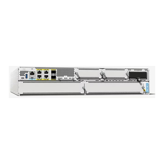
Page 10: Chassis Views
Overview Chassis Views Chassis Views This section contains views of the Power Supply and I/O sides of the Cisco Catalyst 8300 Series Edge Platforms, showing the locations of power and signal interfaces, module slots, status indicators, and chassis identification labels: Cisco Catalyst 8300 Series Edge Platforms are available in these models: •... - Page 11 RJ-45 Console RJ-45 Gigabit Ethernet port (1G 0/0/0) RJ-45 Gigabit Ethernet port (1G 0/0/2) SFP+/10 Gigabit Ethernet port (10G 0/0/4) for C8300-2N2S-4T2X SFP/1 Gigabit Ethernet port (1G 0/0/4) for C8300-2N2S-6T Hardware Installation Guide for Cisco Catalyst 8300 Series Edge Platforms...
-
Page 12: Platform Summary
For detailed information on LEDs, see the section on LED indicators. Platform Summary The figure below shows the internal view of Cisco Catalyst 8300 Series Edge Platforms with components and module locations. Hardware Installation Guide for Cisco Catalyst 8300 Series Edge Platforms... - Page 13 Overview Platform Summary Figure 5: Platform Summary of C8300-1N1S-4T2X|6T DIMM M.2 card slot slot Hardware Installation Guide for Cisco Catalyst 8300 Series Edge Platforms...
-
Page 14: Locating Labels On Cisco Catalyst 8300 Series Edge Platforms
Location of labels on Cisco Catalyst 8300 Series Edge Platforms The figure below shows the location of the labels on the Cisco Catalyst 8300 Series Edge Platforms. Labels are located at the same location on all the Cisco Catalyst 8300 Series Edge Platforms... - Page 15 Overview Location of labels on Cisco Catalyst 8300 Series Edge Platforms The Serial number (SN), Common language equipment identifier (CLEI), Top Assembly Number (TAN), Product ID (PID), PID version ID (VID), and Quick response (QR) code are printed on a label on the back of the platform or on a label tray located on the chassis.
-
Page 16: Locate Product Identification Details
The serial number (SN), product ID (PID), version ID (VID), and Common Language Equipment Identifier (CLEI) are printed on a label on the bottom of the device or on the label tray. Hardware Installation Guide for Cisco Catalyst 8300 Series Edge Platforms... -
Page 17: Hardware Features Of Cisco Catalyst 8300 Series Edge Platforms
• Product ID (PID) • Serial number (SN) The UDI can be viewed using the show license udi command in privileged Exec mode in Cisco Internet Operating System (IOS) software. For additional information on the UDI, see the << >>document on cisco.com. -
Page 18: Removable And Interchangeable Modules And Cards
LTE related signals through the I2C interface of the pluggable module. Internal Slots • Memory See the Cisco Catalyst 8300 Series Edge Platforms product page on cisco.com for a list of supported modules and interface cards. Memory Cisco Catalyst 8300 Series Edge Platforms contain DIMMs that store running configuration and routing tables, and are used for packet buffering by the network interfaces. -
Page 19: Leds For Cisco Catalyst 8300 Series Edge Platforms
Red Blinking Red: The system has failed a hardware integrity error Yellow: Rommon has completed booting and system is at Rommon prompt or booting platform software. Green: Normal System Operation Hardware Installation Guide for Cisco Catalyst 8300 Series Edge Platforms... -
Page 20: Fans, Ventilation, And Airflow
The chassis temperature is regulated with internal fans. An onboard temperature sensor controls the fan speed. The fans are always on when the device is powered on. Under all conditions, the fans operate at the slowest Hardware Installation Guide for Cisco Catalyst 8300 Series Edge Platforms... -
Page 21: Slots, Subslots-Bay, Ports, And Interfaces
Figure 10: Airflow of C8300-2N2S-4T2X|6T Slots, Subslots-Bay, Ports, and Interfaces The Cisco Catalyst 8300 Series Edge Platforms support interface modules: Service Modules (SM) and Network Modules (NIMs) and Pluggable Interface Modules (PIMs). Hardware Installation Guide for Cisco Catalyst 8300 Series Edge Platforms... -
Page 22: Slot Numbering
• Integrated devices, also known as integrated ports or FPGEs, and NIMs reside in a fixed section of bay • Motherboard NIMs bays start at bay 1 because the integrated devices and integrated NIMs take up bay Hardware Installation Guide for Cisco Catalyst 8300 Series Edge Platforms... -
Page 23: Prepare For Installation
Note: SAVE THESE INSTRUCTIONS Statement 1071 General Safety Warnings Warning Read the installation instructions before you connect the system to its power source. Statement 1004 Hardware Installation Guide for Cisco Catalyst 8300 Series Edge Platforms... - Page 24 Electrical Appliance and Material Safety Law prohibits the use of certified cables (that have the ‘UL’ shown on the code) for any other electrical devices than products designated by Cisco. The use of cables that are certified by Electrical Appliance and Material Safety Law (that have ‘PSE’ shown on the code) is not limited to Cisco-designated products.
- Page 25 (EMI) that might disrupt other equipment; and they direct the flow of cooling air through the chassis. Do not operate the system unless all cards, faceplates, front covers, and rear covers are in place. Statement 1029 Hardware Installation Guide for Cisco Catalyst 8300 Series Edge Platforms...
- Page 26 Avoid using a telephone (other than a cordless type) during an electrical storm. There may be a remote risk of electric shock from lightning. Statement 1038 Warning To report a gas leak, do not use a telephone in the vicinity of the leak. Statement 1039 Hardware Installation Guide for Cisco Catalyst 8300 Series Edge Platforms...
- Page 27 This equipment is suitable for installations utilizing the insert CBN. Statement 7013 Warning This equipment is suitable for installation in network telecommunications facilities. Statement 8015 Warning This equipment is suitable for installation in locations where the NEC applies. Statement 8016 Hardware Installation Guide for Cisco Catalyst 8300 Series Edge Platforms...
-
Page 28: Safety Recommendations
• Do not work alone if hazardous conditions exist • Never assume that power is disconnected from a circuit. Always check • Never open the enclosure of the internal power supply Hardware Installation Guide for Cisco Catalyst 8300 Series Edge Platforms... -
Page 29: Prevent Electrostatic Discharge Damage
Ensure that the site is properly prepared before beginning installation. If you are experiencing shutdowns or unusually high errors with your existing equipment, the guidelines provided in this section can also help you isolate the cause of failures and prevent future problems. Hardware Installation Guide for Cisco Catalyst 8300 Series Edge Platforms... -
Page 30: General Precautions
Prepare for Installation General Precautions General Precautions Observe the following general precautions when using and working with your Cisco Catalyst 8300 Series Edge Platforms: • Keep your system components away from radiators and heat sources, and do not block cooling vents. -
Page 31: Physical Characteristics
Router Environmental Requirements Cisco Catalyst 8300 Series Edge Platforms can be placed on a desktop or installed in a rack. The location of your router and the layout of your equipment rack or wiring room are extremely important considerations for proper operation. -
Page 32: Power Guidelines And Requirements
• All units include a 6-foot (1.8-meter) electrical power cord. (A label near the power inlet indicates the correct voltage, frequency [only AC-powered systems], and current draw for the unit.) For additional information on the power requirements, refer to the Cisco Catalyst 8300 Series Edge Platforms datasheet. -
Page 33: Eia/Tia-232
To avoid electric shock, do not connect safety extra-low voltage (SELV) circuits to telephone-network voltage (TNV) circuits. LAN ports contain SELV circuits, and WAN ports contain TNV circuits. Some LAN and WAN ports both use RJ-45 connectors. Statement 1021 Hardware Installation Guide for Cisco Catalyst 8300 Series Edge Platforms... -
Page 34: Ethernet Connections
Statement 1091 You need the following tools and equipment to install and upgrade the router and its components: • ESD-preventive cord and wrist strap • Number 2 Phillips screwdriver Hardware Installation Guide for Cisco Catalyst 8300 Series Edge Platforms... - Page 35 • Modem for connection to the auxiliary port for remote administrative access (optional). • Data service unit (DSU) or channel service unit/data service unit (CSU/DSU) as appropriate for serial interfaces. • External CSU for any CT1/PRI modules without a built-in CSU. Hardware Installation Guide for Cisco Catalyst 8300 Series Edge Platforms...
- Page 36 Prepare for Installation Required Tools and Equipment for Installation and Maintenance Hardware Installation Guide for Cisco Catalyst 8300 Series Edge Platforms...
-
Page 37: Install And Connect
C H A P T E R Install and Connect This chapter describes how to install and connect the Cisco Catalyst C8300 Series Edge Platforms to LAN, WAN, and Voice networks. Note These routers are designed to boot up in less than 30 minutes, provided the neighboring devices are in fully operational state. -
Page 38: What You Need To Know
What You Need to Know CLI Console Access Use the USB or RJ-45 console port on the router to access the Cisco Internet Operating System (IOS-XE) and XE SD-WAN command line interface (CLI) on the router and perform configuration tasks. A terminal emulation program is required to establish communication between the router and a PC. -
Page 39: Mount The Chassis On A Desktop
Step 1 Attach the elastomeric mount feet (label 1) to the bottom of the device. The feet come with a pre-applied adhesive. Place the feet in the locations marked by a circle. Step 2 You can place the device on a desktop, bench top, or shelf. Hardware Installation Guide for Cisco Catalyst 8300 Series Edge Platforms... -
Page 40: Rack Mount The Chassis
Rack Mount the Chassis Warning Supply Circuit To reduce risk of electric shock and fire, take care when connecting units to the supply circuit so that wiring is not overloaded. Statement 1018 Hardware Installation Guide for Cisco Catalyst 8300 Series Edge Platforms... -
Page 41: Attach The Rack-Mounting Brackets
Insert the #6-32 FHM screws. Use only the screws that are provided in the rack mount bracket kit. Step 4 Tighten the screws to a torque value of 15 to 18 inch-lb. (1.7 to 2.0 N-m). Hardware Installation Guide for Cisco Catalyst 8300 Series Edge Platforms... - Page 42 Figure 13: Install Brackets for I/O-Side Mounting (C8300-1N1S-4T2X|6T) 19-inch brackets 23-inch brackets #6-32 PHMS Figure 14: Rack Mount Bracket Mounting Positions Flush with I/O side (No RFID) I/O Side Recessed (for RFID) Hardware Installation Guide for Cisco Catalyst 8300 Series Edge Platforms...
- Page 43 Insert the #8-32 FHM screws. Use only the screws that are provided in the rack mount bracket kit. Step 4 Tighten the screws to a torque value of 15 to 18 inch-lb. (1.7 to 2.0 N-m). Hardware Installation Guide for Cisco Catalyst 8300 Series Edge Platforms...
- Page 44 Install and Connect Figure 16: Install Brackets for I/O-Side Mounting (C8300-2N2S-4T2X|6T) 19-inch brackets 23-inch brackets #8-32 FHM screw Hardware Installation Guide for Cisco Catalyst 8300 Series Edge Platforms...
- Page 45 Figure 17: Install Brackets for I/O Center Mounting (C8300-2N2S-4T2X|6T) Flush with I/O Side Mid-Mount from Power Supply Side Figure 18: Install Brackets for PS Mounting (C8300-2N2S-4T2X|6T) Mid-Mount from Power Supply Side Hardware Installation Guide for Cisco Catalyst 8300 Series Edge Platforms...
-
Page 46: Mount The Chassis On A Rack
Step3. Secure the device using mounting screws appropriate for your equipment frame. The rack mount brackets have been designed #12-24 PHM screws. Step4. Tighten the screws to the appropriate torque value for your equipment Hardware Installation Guide for Cisco Catalyst 8300 Series Edge Platforms... - Page 47 Install and Connect Mount the Chassis on a Rack Figure 19: I/O Flush Mount, no RFID (C8300 1N1S-4T2X|6T) Rack Mounting screws Figure 20: I/O Mount with RFID (C8300 1N1S-4T2X|6T) Rack Mounting screws Hardware Installation Guide for Cisco Catalyst 8300 Series Edge Platforms...
- Page 48 Step3. Secure the device using mounting screws appropriate for your equipment frame. The rack mount brackets have been designed #12-24 PHM screws. Step4. Tighten the screws to the appropriate torque value for your equipment Figure 22: Mid-Mount from Power Supply Side (C8300-1N1S-4T2X|6T) Hardware Installation Guide for Cisco Catalyst 8300 Series Edge Platforms...
- Page 49 Mount the Chassis on a Rack Rack Mounting screws Figure 23: Power Supply Side-Mount (C8300 1N1S-4T2X|6T) Rack Mounting screws Figure 24: I/O Mount in Rack (C8300 2N2S-4T2X|6T) Rack Mounting screws Hardware Installation Guide for Cisco Catalyst 8300 Series Edge Platforms...
- Page 50 Install and Connect Mount the Chassis on a Rack Figure 25: Mid Mount from I/O Side (C8300 2N2S-4T2X|6T) Rack Mounting screws Figure 26: Power Supply Side Mount (C8300 2N2S-4T2X|6T) Hardware Installation Guide for Cisco Catalyst 8300 Series Edge Platforms...
-
Page 51: Attach Cisco Cisco Catalyst 8300 Series Edge Platforms On A Wall
Install and Connect Attach Cisco Cisco Catalyst 8300 Series Edge Platforms on a Wall Rack Mounting screws Figure 27: Mid-Mount from Power Supply Side (C8300 2N2S-4T2X|6T) Rack Mounting screws Attach Cisco Cisco Catalyst 8300 Series Edge Platforms on a Wall Caution Only the C8300-1N1S-4T2X|6T are designed to be wall mounted. - Page 52 Install and Connect Attach Cisco Cisco Catalyst 8300 Series Edge Platforms on a Wall Step 2 The outer face of the rack mount bracket ear, the part that typically mounts to an equipment rack, should be placed against the side of the router. Use the spacers provided to adapt the larger obround holes down to smaller holes for the screws to fit into.
-
Page 53: Ground The Chassis
You must connect the chassis to a reliable earth ground; the ground wire must be installed in accordance with local electrical safety standards. • For grounding, use size 6 AWG (13 mm² ) copper wire and the ground lug provided in the accessory kit. Hardware Installation Guide for Cisco Catalyst 8300 Series Edge Platforms... - Page 54 For a ring terminal, use one of the screws provided. Tighten the screws to a torque of 8 to 10 in-lb (0.9 to 1.1 N-m). Hardware Installation Guide for Cisco Catalyst 8300 Series Edge Platforms...
-
Page 55: Connect Power To The Device
Connect the other end of the ground wire to a known reliable earth ground point at your site. Ground lug Connect Power to the Device This section explains how to connect power to the device. Hardware Installation Guide for Cisco Catalyst 8300 Series Edge Platforms... - Page 56 Material Safety Law prohibits the use of UL-certified cables (that have the “UL” shown on the code) for any other electrical devices than products designated by CISCO. The use of cables that are certified by Electrical Appliance and Material Safety Law (that have “PSE” shown on the code) is not limited to CISCO-designated products.
-
Page 57: Connect To A Console Terminal Or Modem
The Catalyst 8300 Series Edge Platforms have asynchronous serial ports. These ports provide administrative access to the router either locally (with a console terminal or a PC).To configure the router through the Cisco IOS CLI, you must establish a connection between the router console port and either a terminal or a PC. -
Page 58: Connect To The Console Port With Linux
Step 3 Click Next on the Installation Wizard, then click Finish to complete installation. Step 4 Open the Device Manager on your system and click the Ports (COM & LPT) drop-down. Hardware Installation Guide for Cisco Catalyst 8300 Series Edge Platforms... -
Page 59: Install The Silicon Labs Mac Usb Device Driver
Never install telephone jacks in wet locations unless the jack is specifically designed for wet locations. Statement 1036. Warning Never touch uninsulated telephone wires or terminals unless the telephone line has been disconnected at the network interface. Statement 1037. Hardware Installation Guide for Cisco Catalyst 8300 Series Edge Platforms... -
Page 60: Ports And Cabling
Statement 1088. Ports and Cabling The connections summarized here are also described in detail in the document on Cisco.com: Cisco Modular Access Cable Specifications Table 10: WAN, LAN, and Voice Connections... - Page 61 Note After installing the device and connecting the cables, you can configure the device with basic configurations. For more information on how to configure the device, see the Cisco Catalyst 8300 Series Edge Platforms Software Configuration Guide. Hardware Installation Guide for Cisco Catalyst 8300 Series Edge Platforms...
- Page 62 Install and Connect Connection Procedures and Precautions Hardware Installation Guide for Cisco Catalyst 8300 Series Edge Platforms...
-
Page 63: Install Internal Components And Field Replaceable Units
C H A P T E R Install Internal Components and Field Replaceable Units This document describes how to install internal components and field replaceable units (FRUs) in the Cisco Catalyst 8300 Series Edge Platforms. The installation information is contained in these sections: •... -
Page 64: Locate And Access Internal Components
May 8, 2019.. Statement 1255 Locate and Access Internal Components The figures below show the locations of internal components on the motherboard. Internal modules include DIMMs on Cisco Catalyst 8300 Series Edge Platforms. Hardware Installation Guide for Cisco Catalyst 8300 Series Edge Platforms... - Page 65 Install and Remove Chassis Covers. Figure 32: Internal Component Locations in the C8300-1N1S-4T2X|6T Sl. No Modules Fan tray DIMM Hardware Installation Guide for Cisco Catalyst 8300 Series Edge Platforms...
-
Page 66: Remove And Replace The Chassis Cover
DIMMs Remove and Replace the Chassis Cover The Cisco Catalyst 8300 Series Edge Platforms have removable covers. Before removing the cover, do these steps: • Do not run the device with the cover off. Doing so can cause the chassis to overheat very quickly. -
Page 67: Replace The Cover
EMC Gaskets. Step 3 For C8300-1N1S-4T2X|6T install the 11 cover screws. For C8300-2N2S-4T2X|6T install the 6 cover screws. Figure 34: Install the Cover on the C8300-1N1S-4T2X|6T Chassis cover Screws Chassis Hardware Installation Guide for Cisco Catalyst 8300 Series Edge Platforms... -
Page 68: Remove And Replace Ddr Dimms
Always wear an ESD-preventive wrist strap and ensure that it makes good contact with your skin when you remove or install DIMMs. Connect the equipment end of the wrist strap to the metal part of the chassis. Hardware Installation Guide for Cisco Catalyst 8300 Series Edge Platforms... -
Page 69: Locate And Orient Dimm
If the cover is not already removed, remove the chassis cover. Step 3 Locate the DIMM module to find the DIMM sockets on the chassis. Step 4 Rotate DIMM connector handles downwards to extract the DIMM module. Hardware Installation Guide for Cisco Catalyst 8300 Series Edge Platforms... -
Page 70: Install A Dimm
Figure 37: Remove a DIMM Install a DIMM Follow these steps to install a DIMM on the Cisco Catalyst 8300 Series Edge devices. Step 1 Read the Safety Warnings section and disconnect the power supply before you perform any DIMM replacement. -
Page 71: Remove And Replace The Power Supplies
This may then result in the system being unstable or unusable. Hardware Installation Guide for Cisco Catalyst 8300 Series Edge Platforms... -
Page 72: Ac Power Supplies
The AC power supplies for C8300-1N1S-4T2X|6T devices are as follows. The two supplies are physically similar and a diagram is shown in the figure below. • PWR-CC1-250WAC • PWR-CC1-500WAC Figure 40: 250W/500W AC Power Supply for C8300-1N1S-4T2X|6T Sl. No Module PSU1 PSU0 Hardware Installation Guide for Cisco Catalyst 8300 Series Edge Platforms... - Page 73 The AC power supplies for C8300-2N2S-4T2X|6T devices are as follows. The two supplies are physically similar and a diagram is shown in the figure below. • PWR-CC1-650WAC • PWR-CC1-1000WAC Hardware Installation Guide for Cisco Catalyst 8300 Series Edge Platforms...
- Page 74 Install Internal Components and Field Replaceable Units Overview of the AC Power Supply Figure 42: 650WAC/1000WAC Power Supply for C8300-2N2S-4T2X|6T Sl. No Module PSU0 PSU1 Hardware Installation Guide for Cisco Catalyst 8300 Series Edge Platforms...
-
Page 75: Remove And Replace The Ac And Hvdc Power Supply (C8300-1N1S-4T2X|6T)
Step 5 Remove the AC power cord from the power socket. Step 6 Depress the power supply latch and use the handle to pull the supply out of the device. Hardware Installation Guide for Cisco Catalyst 8300 Series Edge Platforms... - Page 76 Install Internal Components and Field Replaceable Units Remove and Replace the AC and HVDC Power Supply (C8300-1N1S-4T2X|6T) Figure 44: Step 4 Figure 45: Step 5 Hardware Installation Guide for Cisco Catalyst 8300 Series Edge Platforms...
-
Page 77: Remove And Replace The Ac Power Supply (C8300-2N2S-4T2X|6T)
Step 5 Remove the AC power cord from the power socket. Step 6 Depress the power supply latch and use the handle to pull the supply out of the router. Hardware Installation Guide for Cisco Catalyst 8300 Series Edge Platforms... - Page 78 Install Internal Components and Field Replaceable Units Remove and Replace the AC Power Supply (C8300-2N2S-4T2X|6T) Figure 47: Remove an AC Power Supply from the C8300-2N2S-4T2X|6T Hardware Installation Guide for Cisco Catalyst 8300 Series Edge Platforms...
- Page 79 To replace or install an AC power supply into a C8300-2N2S-4T2X|6T device, perform these steps: Step 1 Use the handle to push the power supply into the device. The power supply latch should provide an audible click when the supply is fully seated. Hardware Installation Guide for Cisco Catalyst 8300 Series Edge Platforms...
-
Page 80: Dc Power Supplies
The DC power supply for C8300-1N1S-4T2X|6T devices is shown in the figure below: • PWR-CC1-400WDC • PWR-CC1-400WHV Figure 50: 400WDC Power Supply for C8300-1N1S-4T2X|6T Handle Strain relief Latch Fail LED Status Terminal block Hardware Installation Guide for Cisco Catalyst 8300 Series Edge Platforms... - Page 81 Overview of the DC Power Supplies Figure 51: 400WHV Power Supply for C8300-1N1S-4T2X|6T Power Fail socket Status LED Handle Latch The DC power supply for C8300-2N2S-4T2X|6T devices is shown in the figure below: Hardware Installation Guide for Cisco Catalyst 8300 Series Edge Platforms...
-
Page 82: Remove And Replace The Dc Power Supply (C8300-1N1S-4T2X|6T)
Step 4 At the power distribution panel or at the local circuit breaker, remove the power from the DC power leads (label 1)attached to the power supply to be replaced. Hardware Installation Guide for Cisco Catalyst 8300 Series Edge Platforms... - Page 83 Depress the power supply latch and use the handle to pull the supply out of the device. Figure 53: Remove a DC Power Supply from the C8300-1N1S-4T2X|6T Figure 54: Step 5 Hardware Installation Guide for Cisco Catalyst 8300 Series Edge Platforms...
-
Page 84: Remove And Replace The Dc Power Supply (C8300-2N2S-4T2X|6T)
If there are redundant power supplies in use the router does not have to be shut down prior to replacing the power supply. The power supply may be replaced while the router is in service. Hardware Installation Guide for Cisco Catalyst 8300 Series Edge Platforms... - Page 85 Step 6 Depress the power supply latch and use the handle to pull the supply out of the device. Figure 56: Remove a DC Power Supply from the C8300-2N2S-4T2X|6T Hardware Installation Guide for Cisco Catalyst 8300 Series Edge Platforms...
- Page 86 Install Internal Components and Field Replaceable Units Remove and Replace the DC Power Supply (C8300-2N2S-4T2X|6T) Figure 57: Step 5 Figure 58: Step 6 Hardware Installation Guide for Cisco Catalyst 8300 Series Edge Platforms...
-
Page 87: Install The Dc Input Power
In the C8300-1N1S-4T2X|6T and C8300-2N2S-4T2X|6T platforms, the DC power supply has a terminal block that is installed into the power supply terminal block header. Use the following steps to prepare the wire for connection to the terminal source: Hardware Installation Guide for Cisco Catalyst 8300 Series Edge Platforms... - Page 88 DC input power source wire extends from the terminal block. Statement 122 Identify the positive and negative feed positions for the terminal block connection of C8300-1N1S-4T2X|6T: a) Positive (+) lead wire (right) b) Negative (–) lead wire (left) Hardware Installation Guide for Cisco Catalyst 8300 Series Edge Platforms...
- Page 89 Identify the positive, ground, and negative feed positions for the terminal block connection of C8300-2N2S-4T2X|6T: • Positive (+) lead wire(left) • Ground Lead wire (middle) • Negative (–) lead wire(right) Hardware Installation Guide for Cisco Catalyst 8300 Series Edge Platforms...
-
Page 90: Remove And Install Poe Converter Power Supply Unit
The optional PoE converter PSU slots come with factory-installed fillers. You must remove them to install the PoE converter power supplies. If you are using only one PoE converter power supply, you must install the PoE converter power supply in PoE slot 0. Hardware Installation Guide for Cisco Catalyst 8300 Series Edge Platforms... -
Page 91: Remove The Poe Power Supply Slot Filler
Install the tab on the left side of the filler panel into the slot in the chassis. Step 2 Tighten the screw to secure the filler panel in the chassis. Step 3 Install the fan tray from the device. Hardware Installation Guide for Cisco Catalyst 8300 Series Edge Platforms... -
Page 92: Remove The Poe Converter Power Supply
PoE converter module being installed in PoE slot PoE converter module installed in PoE slot 0 Screws to secure PoE module to the chassis. Latch to secure PoE converter module (shown closed). Hardware Installation Guide for Cisco Catalyst 8300 Series Edge Platforms... -
Page 93: Install The Poe Converter Power Supply
The following messages are expected behavior when you try to reload or insert a PoE supply in a device with Ethernet Switch Network Module: Example: *Jul 21 22:35:23.868: %IOSXE_PEM-6-INSPEM_FM: PEM/FM slot POE0 inserted Upon PoE converter power supply insertion, inline power supply restores automatically in the router. Hardware Installation Guide for Cisco Catalyst 8300 Series Edge Platforms... -
Page 94: Replace A Fan Tray For Cisco Catalyst 8300 Series Edge Platforms
Replace a Fan Tray for Cisco Catalyst 8300 Series Edge Platforms In the Cisco Catalyst 8300 Series Edge Platforms, we have fan trays that are field replaceable units (FRUs). The fan tray includes all the fans in one assembly. If a fan fails, replace the tray using a #1 Phillips screwdriver. -
Page 95: Remove The Fan Tray Air Filter From A C8300-2N2S-4T2X|6T
• Air filters cannot be cleaned and reused. Replace with a new air filter. It is recommended to have spare air filters in stock. Remove the Fan Tray from a C8300-1N1S-4T2X|6T The C8300-1N1S-4T2X|6T supports forward air flow (standard version). Hardware Installation Guide for Cisco Catalyst 8300 Series Edge Platforms... -
Page 96: Install The Fan Tray Into A C8300-1N1S-4T2X|6T
To replace the fan tray, perform these steps: Step 1 Install the fan tray Step 2 Install the three fan tray mounting screws Step 3 Connect the fan cables to the motherboard Hardware Installation Guide for Cisco Catalyst 8300 Series Edge Platforms... -
Page 97: Install And Remove Sfp And Sfp+ Modules
This time is recommend to alllow the transceiver software to initilize and synchronise with the standby RSP. Chaning an SFP more quickly could result in transceiver initialization issues that disable the SFP Hardware Installation Guide for Cisco Catalyst 8300 Series Edge Platforms... -
Page 98: Laser Safety Guidelines
IEC 60825-1 Ed. 3 as described in Laser Notice No. 56, dated May 8, 2019. Statement 1255. To install an SFP module in your device, perform these steps: Hardware Installation Guide for Cisco Catalyst 8300 Series Edge Platforms... -
Page 99: Remove Small Form Pluggable Modules
SFP modules use various latch designs to secure the module in the SFP port. Latch designs are not linked to Note SFP model or technology type. For information on the SFP technology type and model, see the label on the side of the SFP. Hardware Installation Guide for Cisco Catalyst 8300 Series Edge Platforms... -
Page 100: Remove And Replace The Usb Flash Token Memory Stick
Grasp the SFP on both sides and remove it from the device. Remove and Replace the USB Flash Token Memory Stick The Cisco Catalyst 8300 Series Edge Platforms contain ports for a USB memory stick to store Cisco configurations or Cisco IOS XE consolidated packages. -
Page 101: Remove And Install An M.2 Usb|Nvme Module
What to do next This completes the USB Flash memory installation procedure. Remove and Install an M.2 USB|NVMe Module This section describes installing and replacing an M.2 USB|NVMe module on the Cisco Catalyst 8300 Series Edge Platforms. Prevent Electrostatic Discharge Damage The M.2 module is sensitive to electrostatic discharge (ESD) damage, which can occur when electronic cards... -
Page 102: Remove The M.2 Usb|Nvme Module
Loosen 2 mounting screws using a #1 Philips screwdriver. Step 3 Gently pull the M.2 USB|NVMe module out and remove it from the device. Figure 70: Remove the M.2 USB|NVMe Module (C8300-2N2S-4T2X|6T) Hardware Installation Guide for Cisco Catalyst 8300 Series Edge Platforms... -
Page 103: Install The M.2 Usb|Nvme Module
Screw down and tighten the two Philips head screws. Torque it to 4-6 in lbs. Step 5 The device can now be powered on. Figure 71: Install the M.2 USB|NVMe (C8300-1N1S-4T2X|6T) USB|NVMe Hardware Installation Guide for Cisco Catalyst 8300 Series Edge Platforms... - Page 104 Install Internal Components and Field Replaceable Units Install the M.2 USB|NVMe Module Hardware Installation Guide for Cisco Catalyst 8300 Series Edge Platforms...
-
Page 105: Install Cisco Catalyst Network Interface Module
Install Network Interface Modules in the NIM Adapter, on page 102 Overview of the Network Interface Module The Cisco Catalyst Network Interface Module (NIM), which has 10G WAN and 1xSFP+ 10G port is supported on Cisco Catalyst 8300 Series Edge Platforms. -
Page 106: Remove And Install Network Interface Modules
Remove and Install Network Interface Modules Keep the following tools and equipment while working with the Network Interface Modules (NIM)s: • Number 1 Phillips screwdriver or a small flat-blade screwdriver • ESD-preventive wrist strap Hardware Installation Guide for Cisco Catalyst 8300 Series Edge Platforms... -
Page 107: Remove The Network Interface Module
Step 7 Connect the module to the network and re-enable the power to the slot in the device. Remove and Install Network Interface Modules Adapter This section provides information for before and during the installation of the Cisco Catalyst NIM adapter for two Cisco network interface modules (NIMs) on the Cisco Catalyst 8300 Series Edge Platforms. -
Page 108: Remove The Network Interface Module Adapter
Procedure To remove the Cisco Catalyst NIM adapter from a service module (SM) slot on a Cisco Catalyst 8300 Series Edge Platforms: Step 1 Locate the NIM adapter to be removed. Using a number 1 Phillips or flat-blade screwdriver, unscrew the captive mounting screws on the module faceplate. -
Page 109: Install Network Interface Module Adapter
Procedure To install the Cisco Catalyst NIM adapter into a service module (SM) slot on a Cisco Catalyst 8300 Series Edge Platforms: 1. Remove the blank faceplate installed over one of the device SM slots. The position of the slots depends on the platform's form factor: 1 rack unit (RU) or 2 RU, as shown below. -
Page 110: Install Network Interface Modules In The Nim Adapter
Follow the instructions for installing the NIM. Install Network Interface Modules in the NIM Adapter The Cisco Catalyst NIM adapter provides two network interface module (NIM) slots. To install a NIM into the adapter, follow the instructions for the NIM. -
Page 111: Install Cisco Catalyst Service Module
C H A P T E R Install Cisco Catalyst Service Module This section describes how to install the Cisco Catalyst Service Modules on the Cisco Catalyst 8300 Series Edge Platforms. The service modules supported on the on the Cisco Catalyst 8300 Series Edge Platforms are: •... -
Page 112: Remove The Cisco Catalyst Service Module
This section describes how to install the service modules. Note For illustration purposes, we have used images of Cisco C-SM-X-16P4M2X and C-SM-X-40P8M2X. After the device boots up, insert either C-SM-X-16P4M2X or the C-SM-X-40P8M2X module into the slot of the chassis. A system message displays: : Jun 10 13:58:14.367 CST: %IOMD-3-UNSUPPORTED_NGSWITCH: R0/0: iomd: The message denotes that the system is in legacy switching mode. - Page 113 The latches assist to fully insert the module before securing the screws. Step 6 Using a number 1 Phillips or flat-blade screwdriver, tighten the captive mounting screws on the module faceplate. Hardware Installation Guide for Cisco Catalyst 8300 Series Edge Platforms...
- Page 114 Install Cisco Catalyst Service Module Install a Cisco Catalyst Service Module Hardware Installation Guide for Cisco Catalyst 8300 Series Edge Platforms...
-
Page 115: Cisco Catalyst Pluggable Interface Module
This section provides information before and during the installation of Cisco Catalyst Pluggable Interface Module (PIM) on the Cisco Catalyst 8300 Series Edge Platforms. For additional information on the supported NIMs, see the Cisco Catalyst 8300 Series Edge Platforms' datasheet on cisco.com for a list of supported PIMs on the platforms. -
Page 116: Safety Recommendations
• Installing or removing a router chassis • Working near power supplies • Do not work alone if potentially hazardous conditions exist. • Always check that power is disconnected from a circuit. Hardware Installation Guide for Cisco Catalyst 8300 Series Edge Platforms... -
Page 117: Tools And Equipment Required During Installation
• Determine if the person needs rescue breathing or external cardiac compressions; then take appropriate action. Tools and Equipment Required During Installation You will need the following tools and equipment while working with the Cisco C-NIM-1X NIM: • Number 1 Phillips screwdriver or a small flat-blade screwdriver • ESD-preventive wrist strap... -
Page 118: Configuring A Pluggable Interface Module
SIM 0 LED SIM 1 LED GPS LED M3.5 thumb-screw Service LED Configuring a Pluggable Interface Module To insert the antenna in the Pluggable Interface Module, perform the below steps: Hardware Installation Guide for Cisco Catalyst 8300 Series Edge Platforms... - Page 119 After installing the antennas, adjust the antenna orientation by spacing out each of them equally until they are spread out. This is important as it helps in getting higher RF performance. Hardware Installation Guide for Cisco Catalyst 8300 Series Edge Platforms...
-
Page 120: Rf Band Mapping For Antenna Ports (For P-5Gs6-Gl Only)
Hardware Installation Guide for Cisco Catalyst 8300 Series Edge Platforms... -
Page 121: Attaching The Antennas
5G NR FR1 n1, n2, n3, n7, n25, n38, n40, n41, n48, n66, n77, n78, n79 Attaching the Antennas To attach the antenna in the Pluggable Interface Module, perform the below steps: Hardware Installation Guide for Cisco Catalyst 8300 Series Edge Platforms... - Page 122 1. Attach each SMA cable to the ports as indicated in the table mappings. 2. Ensure that you tighten and secure each SMA cable into the SMA connector on the PIM. Hardware Installation Guide for Cisco Catalyst 8300 Series Edge Platforms...
- Page 123 DIV 0 ANT 2 DIV 1 (LTE4) DIV 1 ANT 3 GNSS connection The following link contains the antenna specifications and installation instructions for 5G NR (5G-ANTM-O-4-B): https://www.cisco.com/c/en/us/td/docs/routers/connectedgrid/antennas/installing-combined/ b-cisco-industrial-routers-and-industrial-wireless-access-points-antenna-guide/m-5g-antm-04b.html#Cisco_ Generic_Topic.dita_e780a6fe-fa46-4a00-bd9d-1c6a98b7bcb9 Hardware Installation Guide for Cisco Catalyst 8300 Series Edge Platforms...
- Page 124 Cisco Catalyst Pluggable Interface Module Attaching the Antennas Hardware Installation Guide for Cisco Catalyst 8300 Series Edge Platforms...
-
Page 125: Online Insertion And Removal And Hot-Swapping
OIR operation on multiple modules within a router, perform the operation one module at a time. The difference between hot-swapping and OIR is that OIR requires executing Cisco IOS commands before and after the OIR. Hot-swapping is strictly a hardware function and does not require the execution commands. -
Page 126: Remove A Module
*Nov 11 21:06:17.546: %ATMOC3POM-6-SFP_IN: Interface ATM2/0 OC3 MM SFP has been inserted. Router# *Nov 11 21:06:19.442: %LINK-3-UPDOWN: Interface ATM2/0, changed state to up *Nov 11 21:06:20.442: %LINEPROTO-5-UPDOWN: Line protocol on Interface ATM2/0, changed state to up Hardware Installation Guide for Cisco Catalyst 8300 Series Edge Platforms...