Cisco 5500 Manual
Multiswitch router
Hide thumbs
Also See for 5500:
- Configuration manual (40 pages) ,
- Installation manual (34 pages) ,
- Configuration manual (50 pages)
Table of Contents
Advertisement
Quick Links
Maintaining the Cisco Catalyst 5500 Multiswitch
Router
This chapter contains recommended hardware maintenance procedures for the Cisco Catalyst 5500
Multiswitch Routers (MSRs), which provide an Ethernet backbone for connections between the
Cisco Signaling Link Terminals (SLTs), Cisco Media Gateway Controllers (MGCs), and Cisco Media
Gateways (MGWs). You can configure several virtual LANs (VLANs) on the Catalyst 5500s and the
route switch modules (RSMs) provide inter-VLAN routing when necessary. If your solution includes
two Catalyst 5500s, they are connected through an Inter-Switch Link (ISL) trunk, enabling them to share
VLAN data and provide ensured availability.
This chapter describes hardware maintenance; for information on upgrading and maintaining
Catalyst 5500 software, refer to the Cisco Media Gateway Controller Software Release 7 Installation
and Configuration Guide.
This chapter includes the following sections:
•
•
Checking Equipment Status
Check the status of the Cisco Catalyst 5500, using the following methods:
•
•
•
Cisco Catalyst 5500 LEDs
LEDs of the Catalyst 5500 may vary, depending on which components are installed. The LEDs described
in this section are factory default.
OL-0542-06
Checking Equipment Status, page 7-1
Replacing Hardware Components, page 7-5
Reading the Cisco Catalyst 5500 LEDs
Querying the status using the Catalyst command line interface (CLI)
Querying the system using CiscoWorks 2000 and Cisco WAN Manager (CWM)
Cisco MGC Software Release 7 Operations, Maintenance, and Troubleshooting Guide
C H A P T E R
7
7-1
Advertisement
Table of Contents

Related Manuals for Cisco 5500


Summary of Contents for Cisco 5500
- Page 1 Querying the system using CiscoWorks 2000 and Cisco WAN Manager (CWM) • Cisco Catalyst 5500 LEDs LEDs of the Catalyst 5500 may vary, depending on which components are installed. The LEDs described in this section are factory default. Cisco MGC Software Release 7 Operations, Maintenance, and Troubleshooting Guide...
- Page 2 Power supply in left bay is not operational, switched off, or not receiving power. Power supply in the left bay is off or not installed. The Catalyst 5500 power supply LED is red when no modules Note are installed. Green The power supply in the right bay is operational.
- Page 3 If the link is bad and has been disabled due to a hardware failure, the LED flashes orange. If no signal is detected, the LED is off. Figure 7-2 Ethernet Switching Module (10BaseT 24 Port) LEDs ETHERNET SWITCHING MODULE Cisco MGC Software Release 7 Operations, Maintenance, and Troubleshooting Guide OL-0542-06...
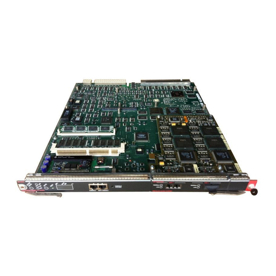
- Page 4 10/100 Mbps FAST ETHERNET SWITCHING MODULE Route Switch Module LEDs The RSM (product number WS-X5302) LEDs, shown in Figure 7-4, are described in Table 7-3. Figure 7-4 RSM (WS-X5302) LEDs ROUTE SWITCH MODULE Cisco MGC Software Release 7 Operations, Maintenance, and Troubleshooting Guide OL-0542-06...
-
Page 5: Replacing Hardware Components
3. ms = milliseconds Using the Command Line Interface to Check Status The Cisco Catalyst 5500 command line interface includes a series of commands that enable you to determine if the MSR is functioning correctly or where problems have occurred. Relevant commands for checking status include ping, traceroute, test snmp trap, and show. -
Page 6: Tools Required
Grasp the left and right ejector levers and simultaneously pull the left lever to the left and the right lever Step 3 to the right to release the module from the backplane connector. Cisco MGC Software Release 7 Operations, Maintenance, and Troubleshooting Guide OL-0542-06... - Page 7 The Flash memory (PCMCIA) card slots on the front panel of Supervisor Engine III are for additional PCMCIA-based Flash memory. You can use this Flash memory to store and run Cisco IOS images, or to serve as an I/O device. Occasionally, it might be necessary to remove and replace Flash memory cards;...
-
Page 8: Removing And Replacing The Power Supply
Remove the card from the slot and place it in an antistatic bag. Removing and Replacing the Power Supply This section describes the procedure you use to remove and install power supplies for the Cisco Catalyst 5500 switches. Use a flat-blade screwdriver to perform these procedures. -
Page 9: Removing An Ac-Input Power Supply
Grasp the power supply handle with one hand and place your other hand underneath to support the bottom of the supply, as shown in Figure 7-8 (Cisco Catalyst 5000 supply shown). Cisco MGC Software Release 7 Operations, Maintenance, and Troubleshooting Guide OL-0542-06... -
Page 10: Installing An Ac-Input Power Supply
Step 1 Failure to turn off the power supply could result in equipment damage. Caution Use both hands to install and remove power supplies. The Cisco Catalyst 5500 power supply weighs 22 Caution lb. (9.9 kg). Keep your hands and fingers out of the power supply bays. High current is present on the power Warning backplane when the system is operating. -
Page 11: Removing A Dc-Input Power Supply
Each AC-input power supply operating at 120 VAC requires a dedicated 20A service and 20A plug and Note receptacle. It is not acceptable to power the Cisco Catalyst 5500 from a 15A line cord because of the safety ratings under which the Cisco Catalyst 5500 is certified. - Page 12 Grasp the power supply handle with one hand and place your other hand underneath as you slowly pull Step 7 the power supply out of the bay (see Figure 7-11). Cisco MGC Software Release 7 Operations, Maintenance, and Troubleshooting Guide 7-12 OL-0542-06...
-
Page 13: Installing A Dc-Input Power Supply
48/60 14.0/8.0 A If the bay is to remain empty, install a blank power supply filler plate (Cisco part number 700-00177-01) Step 8 over the opening and secure it with the mounting screws. This protects the inner chassis from dust and prevents accidental contact with live voltage at rear of the bay. - Page 14 After ensuring that all wire connections are secure, reinstall the terminal block cover. To prevent a short-circuit or shock hazard after wiring the DC-input power supply, reinstall the terminal Caution block cover. Cisco MGC Software Release 7 Operations, Maintenance, and Troubleshooting Guide 7-14 OL-0542-06...
-
Page 15: Removing And Replacing The Chassis Fan Assembly
Perform the following steps to remove the existing chassis fan assembly: Never operate the system if the fan assembly is removed or if it is not functioning properly. An Caution overtemperature condition can result in severe equipment damage. Cisco MGC Software Release 7 Operations, Maintenance, and Troubleshooting Guide 7-15 OL-0542-06... -
Page 16: Installing The Fan Assembly
Push the fan assembly into the chassis until the captive installation screws meet the chassis. Step 3 Tighten the captive installation screws by turning them clockwise. Step 4 Figure 7-13 Cisco Catalyst 5500 Chassis Fan Assembly SUPERVISOR ENGINE SUPERVISOR ENGINE Cisco MGC Software Release 7 Operations, Maintenance, and Troubleshooting Guide 7-16 OL-0542-06... -
Page 17: Checking The Installation
If after several attempts the fans do not operate, or if you experience trouble with the installation (for instance, if the captive installation screws do not align with the chassis holes), contact the Cisco Technical Assistance Center (TAC) for assistance. Refer to the “Obtaining Technical Assistance”... - Page 18 Chapter 7 Maintaining the Cisco Catalyst 5500 Multiswitch Router Replacing Hardware Components Cisco MGC Software Release 7 Operations, Maintenance, and Troubleshooting Guide 7-18 OL-0542-06...