Honeywell BW RigRat User Manual
Local area gas monitor
Hide thumbs
Also See for BW RigRat:
- User manual (76 pages) ,
- Quick start manual (2 pages) ,
- Installation manual (2 pages)
Table of Contents
Advertisement
Quick Links
Advertisement
Table of Contents

Related Manuals for Honeywell BW RigRat


Summary of Contents for Honeywell BW RigRat
- Page 1 Honeywell BW™ RigRat LOCAL AREA GAS MONITOR...
-
Page 3: Table Of Contents
Table of Contents Honeywell BW™ RigRat Safety Standard Contents General Information Certification General Wireless Module Configuration Sensor Configuration Electrical Parameters Type Designation Key Features User Interface Display Overview Screen Display for Various Numbers of Active Sensors Info Mesh/LoRa Network Wireless Control... - Page 4 4-20mA IN Cover Communication Ports When Not in Use External Filter Filter Replacement (Pumped) Filter Replacement (Diffusion) Turning the BW RigRat On and Off Turning the BW RigRat On Turning the BW RigRat Off Testing Alarm Indicators Calibration Status Bump Status...
- Page 5 Replacing Sensors Battery Replacement Replacing the Pump RAEMet Sensor Installation Installation Alarms Overview Alarm Signals Alarm Signal Summary Manual Alarms Test Troubleshooting Editing Features Error Codes Specifications Contact Information BW RigRat User Manual...
-
Page 7: Safety
• Calibration intervals and bump test procedures may vary due to national legislation. • Honeywell recommends using calibration gas cylinders containing the gas that is appropriate to the sensor you are using, and in the correct concentration. BW RigRat... - Page 8 AVERTISSEMENT: Afin de prevenir l’inflammation d’atmosphères dangereuse, ne charger le jeu de batteries que dans des emplacement designés non dangereux. Um = 6V Utilisez uniquement un chargeur approuvé. Only charge the battery in safe area in the ambient temperature range 0°C ≤ T ≤ 40°C. BW RigRat User Manual...
- Page 9 Any data download device connected to this instrument must be approved SELV or Class 2 equipment. Use of non-Honeywell components will void the warranty and can compromise the safe performance of this product. Warning: Substitution of components may impair safe performance of this product.
- Page 10 The multi-gas monitor must be calibrated when the device is turned OFF-ON or exposed to a high concentration above the upper limit. The AC charger system of BW RigRat shall only be applied in non-hazardous areas by charger specifically supplied for use with the unit (for example model number ADS- 25SGP-06 05717E, manufactured by HONOR Electric), approved as SELV or Class 2 equipment against IEC 60950 or an equivalent IEC standard.
- Page 11 L’exploitation est autorisée aux deux conditions suivantes: 1) L’appareil ne doit pas produire de brouillage; 2) L’appareil doit accepter tout brouillage radioélectrique subi, même si le brouillage est susceptible d’en compromettre le fonctionnement. BW RigRat User Manual...
- Page 12 As sensor performance may change over time, specifications provided are for brand-new sensors. Make Sure Firmware Is Up To Date For best operation, make sure your monitor is running the latest firmware. BW RigRat User Manual...
-
Page 13: Standard Contents
CHAPTER Standard Contents The BW RigRat is available in various user-specified configurations, each with the accessories shown below. In addition to the instrument, the following are included: Item Part Number AC adapter W03-3044-000 LCD Cover W03-2129-000 Diffusion calibration cap assembly*... -
Page 14: General Information
Explosive Atmospheres – Part 29-1: Gas Detectors - Performance Requirements of Detectors for Flammable Gases [UL 60079-29-1:2019 Ed.2] Explosive Atmospheres – Part 29-1: Gas Detectors - Performance Requirements of Detectors for Flammable Gases [CAN/CSA C22.2 NO. 60079-29-1:17 Ed.2] BW RigRat User Manual... -
Page 15: General
The overall dimensions of the BW RigRat are about 396mm x 288mm x 470mm (15.6” x 11.4” x 18.5”), it consists of an enclosure, 2 rechargeable battery packs P/N 500-0165-000 (or 500-... - Page 16 T4 Ga Edition 5 IEC60079- 26:2006 Edition2 IEC60079- 0:2011 Edition6 LEL Sensor IEC60079- 1 LEL Ex daia II IECEx ULD 16.0016U (Group II, -40 to+60 1:2014-06 75 x C Ga Issue No.1 Edition7 IEC60079- 11:2011 Edition6 BW RigRat User Manual...
-
Page 17: Electrical Parameters
LEL Sensor: Max.1pc Dynament NDIR Sensor: Max.3pcs In addition, there is a noise sensor located inside of the BW RigRat, which can measure the ambient noise. The BW RigRat also contains a THP sensor in pumped version that can measure the ambient temperature, humidity, and gas flow outside. -
Page 18: Type Designation
2: With NB-IoT 3: Fitted with Wi-Fi and NB-IoT Depending on different configurations, the BW RigRat may refer to different types of protection, gas groups, and ambient temperatures, which are specified as below. The onerous restriction shall be taken into consideration in case one of the following is applied. - Page 19 II C A, B, C, & D BWRR100 a-b-1 with Wi-Fi II B C, & D BWRR100 a-b-2 with NB-IoT II B C, & D BWRR100 a-b-3 with Wi-Fi and NB-IoT II B C, & D BW RigRat User Manual...
-
Page 20: Key Features
Key Features Available pumped or diffusion Up to 6 gas sensor slots Supports Bluetooth (BLE)/ Mesh/Wi-Fi/ GPS/ LoRa >25days’ runtime (Low Power version) Wide operating temperature range (-40 to 60° C) Rugged mechanical design BW RigRat User Manual... -
Page 21: User Interface
The backlit display provides visual feedback that includes the sensor types, readings, battery condition, and other functions. 1 Reading value 4 Correction Factor indicator 2 Communication, Pump (if installed), and battery status 5 Sensor type 3 Unit of measure 6 Alerts BW RigRat User Manual... - Page 22 Gas Alarm Bluetooth (BLE) Failure Inert Mode Enabled Pump failure GPS Failure Stealth/Mute Correction Factor Battery (1 bar ≥ 10% remaining, 2 bars ≥ 50%, 3 bars ≥ Button Press 80%) Button Press and Hold Battery error BW RigRat User Manual...
- Page 23 Device Configurator app (shows when a new file is being Strength pushed to RigRat) Paired with Device Configurator app (flashes when data is Mesh Wireless Failed transferring) RF Network Signal Device Configurator app failure Strength RF Network Failed Data Logging BW RigRat User Manual...
- Page 24 Icon Arrangement Status and other information icons are shown at different places on the screen: The top, the “body” (main display), and bottom. BW RigRat User Manual...
- Page 25 Here is how they are organized and located on the screen: Icon Explanation Battery Alarm Battery Level Bluetooth Pump Mesh Signal RF Network (LoRa) Signal Wi-Fi Menu - Disabled Menu - Disable Sensor Selected BW RigRat User Manual...
- Page 26 Body Icon Explanation Battery Alarm Low Battery Bump Test Inert Mode Mobile Network Peak Positive Pump Status STEL Stop Test Detect Test Fail Gas Not Detected During Test Test Positive BW RigRat User Manual...
- Page 27 Icon Explanation Test Warning Waiting for Operation to Complete (animated) Warning! Correction Factor Applied BW RigRat User Manual...
- Page 28 High alarm Low alarm Sensor Disabled Peak STEL alarm TWA alarm Bottom Icon Explanation Alarm, Displayed instead of “Heart” when there’s a gas alarm Bump Test Fail Bump Test Pass Calibration Fail Calibration Pass Click Hold BW RigRat User Manual...
- Page 29 Network disconnect in Closed loop or There is any device in network is alarming Pair Device, Device config. App. failure Status, heartbeat Stealth Mode, Buzzer mute Inert Mode Data Logging fault I/O in normal status I/O in alarm or fault status BW RigRat User Manual...
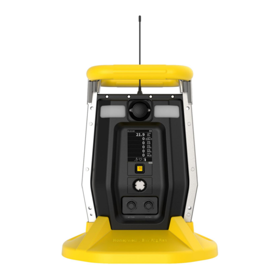
- Page 30 (when in alarm, including cal. overdue), battery status, datalog (if on), and radio and connection quality (if available). Front View Noise Sensor Handle Display Alarm LED Multi-Function Button Alarm Buzzer AC Charge Port IS Charge Port Antenna BW RigRat User Manual...
- Page 31 In addition to turning the instrument on and off, the multi-function button can be used to control different parameters and make selections within the instrument’s menus. Also, pressing the button activates display backlighting when it is off: Press the button once when the backlighting is off to turn it on. BW RigRat User Manual...
-
Page 32: Screen Display For Various Numbers Of Active Sensors
Screen Display for Various Numbers of Active Sensors The BW RigRat can accommodate from one to six sensors. When one or more sensors is either not installed or turned off, the display only shows the installed, active sensors. If one is turned off, it is shown in gray. -
Page 33: Info
The info screens are easy to step through by pressing the button once to advance from one to the next. Hold the button down for secondary actions. Note: In most cases, if no buttons are pressed at any of the menu steps for 60 seconds, the instrument reverts to the main display. BW RigRat User Manual... -
Page 34: Mesh/Lora Network Wireless Control
When you step through the main menu, as shown in the Menus diagram, there is a screen for wireless communication, containing information on wireless settings and status. Note: Wireless settings are only present if the BW RigRat is equipped with a Mesh/LoRa Network wireless module. Settings are managed through the Device Configurator app, under the “Wireless”... -
Page 35: Mesh/Rf Wireless Network (If Supported)
Mesh/RF Wireless Network (if supported) Mesh Closed-Loop Network Note: If the BW RigRat is used as a repeater without sensors, it will display a blank screen. Use the Device Configurator app to set all BW RigRat instruments’ mesh wireless Network Mode to Closed Loop. - Page 36 Mesh Connect to Controller Set the BW RigRat instruments’ mesh wireless Network Mode to STD or Router by using the Device Configurator app. Set the BW RigRatt, Portable devices, Mesh Router, and Controller to have the same PAN ID/Channel. The network is now ready. The BW RigRat instruments will show on the Controller display.
- Page 37 Mesh Connect to Radiant Reader Set the BW RigRat instruments’ mesh wireless Network Mode to STD or RTR by using the Device Configurator app. Set the BW RigRat PAN ID/Channel to be the same as those in Radiant Reader. The BW RigRat now joins the network and can show information on PC software.
- Page 38 RF Network (LoRa) Connect to Central Hub Set the BW RigRat instruments’ RF wireless Network Mode to STD or RTR by using the Device Configurator app. Set the BW RigRat PAN ID/Channel to match those in Central Hub. The BW RigRat is now able to join the network and can show information on Safety Suite software.
-
Page 39: Bluetooth
CHAPTER Bluetooth The BW RigRat is always equipped with a BLE (Bluetooth Low Energy) module, it is easy to use the app on a smartphone or tablet to perform setup functions. BW RigRat User Manual... -
Page 40: Bluetooth Pairing
Select the BW RigRat (text such as “BW RigRat No, HRRD0009001” is printed on the nameplate or on display’s “BLE pairing codes” screen). The BW RigRat display will show a paring code on its bottom line. Input this code in the app’s dialog box. - Page 41 Note: The BW RigRat LCD must be at the main screen when working with the Device Configurator app. Important! Uploading a configuration to a BW RigRat is not possible when the device is in gas alarm or when the battery is near empty.
-
Page 42: Broken Bluetooth Connection
RigRat display. Check for interference (too many Bluetooth communications nearby, too much distance between the BW RigRat and the smartphone). You may need to turn off the BW RigRat and exit the app, and then restart both and re-pair. Note: The Bluetooth connection between a smartphone and a BW RigRat is best within a distance of 5 meters. -
Page 43: Wi-Fi Connection (If Supported)
Wi-Fi Connection (if supported) BW RigRat Wi-Fi is designed to operate on a wireless network anchored by Safety Suite Real Time (SSRT) monitoring software and using Wi-Fi access points. Operational distance between the instrument and the access point (wireless router) varies, depending on such factors as interference and obstacles. - Page 44 Secure Wireless Access Point Configuration If Wi-Fi is enabled, a BW RigRat uses a Wi-Fi wireless network to transmit data related to its current and past activity. To protect these data against unauthorized access, Honeywell recommends the following when configuring your wireless network: Set a unique network name (SSID).
- Page 45 Check with your system administrator for the wireless security mode you should use. Use the drop-down menu to select the type of security. Then set your Security Key. Warning! Using a network with security disabled is not recommended. BW RigRat User Manual...
- Page 46 The SSID (Service Set Identifier) is a case-sensitive unique identifier attached to the header of packets sent over a wireless local-area network. Each wireless network in your range will have its own SSID. Consult with your IT department for the SSID. BW RigRat User Manual...
- Page 47 Test the Wi-Fi Operation Test the BW RigRat in your network to ensure that it communicates properly. Always do this after performing any changes to wireless parameters.
-
Page 48: Secure Wireless Communication
The Network Preshared Key is 32 characters long, and the Mesh User Key is 4 characters. For Mesh/RF or Wi-Fi connection to the server, both the BW RigRat and the server must have the same Network Preshared Key. -
Page 49: Battery Charging
CHAPTER Battery Charging Always fully charge the battery before using the BW RigRat. Its Li-ion batteries are charged by connecting the instrument to its charger (P/N: W03-3044-000) and then plugging the charger into an AC power source. In safe settings, use the AC Charge input with the included power adapter. - Page 50 Intrinsically Safe Runtime Extension for Hazardous Areas If the BW RigRat is to be charged or powered in a hazardous area, then an intrinsically safe (I.S.) barrier box is necessary. Use P/N: W03-3018-000, and connect it to the IS CHG HAZARDOUS port.
- Page 51 Schematic drawing shows how the IS Barrier is configured with the BW RigRat: Intrinsically safe barrier terminals in use IS Barrier Terminal A Safe area, power negative input Terminal B Safe area, power positive input, rated 110~230VAC Terminal H To hazardous area, negative output Terminal L To hazardous area, positive output, max 23.5V/1.15W...
- Page 52 Extension cable (W03-2168-000) W03-2168-000 IS barrier to BW RigRat cable, 100meters, with 3-pin connector. Total 100m cable IS parameters: (C=80pF/m; L=0.7uH/m; R=23.2mΩ /m) Ct=8nF Lt=0.07mH BW RigRat IS parameters in hazardous area: Ui=24V Ii= 150 mA Pi=1.15W Ci=0.36nF. Li=0uH For hazardous applications, these conditions must be met: Uo ≤...
- Page 53 IS charge port. When power is applied and the BW RigRat battery is charging. When the battery is fully charged, the Full Charge icon is shown accompanied by “100%.” If the instrument is off but is being charged, it shows the charge state and percentage.
-
Page 54: Battery States
When the battery power is critically low, the instrument displays a warning that it will be shutting off: The instrument automatically powers down and you will need to recharge the battery before placing the instrument into service again. BW RigRat User Manual... -
Page 55: Wired Communication
CHAPTER Wired Communication The BW RigRat has three ports for external communication. They are labeled as: Serial (not intended to be used in explosive atmospheres) (a) Switch (b) 4-20mA IN (c) BW RigRat User Manual... -
Page 56: Serial (Not Intended To Be Used In Explosive Atmospheres)
Chip select, output Pin D UART port, output Pin E Ground Pin F UART port, input Others Reserved Note: See "RAEMet Sensor Installation" on page 86 for more information. and details on connecting to a RAEMet Sensor. BW RigRat User Manual... -
Page 57: Switch
Switch BW RigRat supports three separate SPST PhotoMOS relay output switch connections for applications where other equipment needs to be controlled (lights, sirens, etc.). Relay Definitions: Relay 1 Any gas sensor failed, or STEL/TWA/+OL/-OL alarms Relay 2 Any high alarms... - Page 58 Po ≤ Pi Co ≥ Ci + Ct Lo ≥ Li + Lt Uo/Io/Po/Co/Lo are IS barrier output parameters; Ui/Ii/Pi/Ci/Li are RigRat input parameters; Ct/Lt are extension cable additional parameters. BW RigRat switch port IS parameters: Ui=30V Ii= 100mA Pi=0.75W Ci=1.1nF Li=0uH...
-
Page 59: 4-20Ma In
The BW RigRat supports a 4-20mA signal input and a no source switch on/off signal input. When 4-20mA input, BW RigRat will check and show the current, also will give an alarm when out of limitation value. When switch signal input, BW RigRat will alarm when switch on. This is for emergency alarm. -
Page 60: Cover Communication Ports When Not In Use
Po ≤ Pi Co ≥ Ci + Ct Lo ≥ Li + Lt Uo/Io/Po/Co/Lo are IS barrier output parameters; Ui/Ii/Pi/Ci/Li are RigRat input parameters; Ct/Lt are extension cable additional parameters. BW RigRat switch port IS parameters: Ui=30V Ii= 100mA Pi=0.75W Ci=0nF. Li=0uH Cover Communication Ports When Not in Use Whenever a port is not in use, make sure the port is covered. -
Page 61: External Filter
RigRat in dirty or dusty environments. Replace the filter when it appears dirty. Filter Replacement (Pumped) The external filter is located on the rear of the BW RigRat: Turn off the BW RigRat. Loosen the two Philips screws that secure the filter. - Page 62 Dispose of the old filter properly. Press a new filter into place. Replace and tighten the two Philips screws. Do not overtighten. BW RigRat User Manual...
-
Page 63: Filter Replacement (Diffusion)
Filter Replacement (Diffusion) If the filters over the sensors appear dirty, replace them. The external filters are located inside the panel on the rear of the BW RigRat: Turn off the BW RigRat. Remove the Rain Protector (if installed). Remove the four screws that hold the Sensor Cover in place. - Page 64 Put the plate back in place. Tighten the four screws. Replace the Rain Protector (if needed). BW RigRat User Manual...
-
Page 65: Turning The Bw Rigrat On And Off
3 seconds. You should charge the battery before turning it on again. IMPORTANT! If a major error that prevents the BW RigRat from functioning is found during startup, the message “Contact Service” is shown on the display. The instrument should be shut off and serviced. - Page 66 Note: If you do not click the button to acknowledge being informed of overdue tests, the instrument will shut itself off in 300 seconds (5 minutes). BW RigRat User Manual...
-
Page 67: Turning The Bw Rigrat Off
Note: if you continue to hold the button during the second 3-second countdown, it enters the main menu. Note: You cannot turn off the BW RigRat if it is in gas alarm. Testing Alarm Indicators Under normal-operation mode and non-alarm conditions, the backlight can be tested by turning the instrument on. -
Page 68: Calibration Status
The defined period of time between calibrations has been exceeded, according to the policy set for the instrument. If you have changed the calibration gas type without recalibrating the instrument. The sensor has failed a previous calibration. BW RigRat User Manual... -
Page 69: Bump Status
A bump test is required if the defined period of time between bump tests has been exceeded. This interval is set by an administrator using Device Configurator. BW RigRat User Manual... -
Page 70: Modes Of Operation
3-2-1 countdown, followed by a second 3-2-1 countdown. Entering Menu Mode With the BW RigRat on, hold the button down through the 3-2-1 countdown, followed by a second 3-2-1 countdown. The password screen appears, release the key. -
Page 71: Diagnostic Mode
Press the button until you reach “Exit.” Diagnostic Mode In Diagnostic Mode, the BW RigRat provides information about the instrument, battery, pump, etc., as well as a list of installed sensors and information about them (expiration date, serial number, etc.). Most of these screens are useful only to service technicians. - Page 72 Noise sensor information (if installed. Hold to start calibration.) GPS information (if installed) LCD test (Hold to start test procedure.) LED and Buzzer test (Hold to start test procedure) Switch output/Digital input/4~20mA information (Hold to test switch output.) BW RigRat User Manual...
-
Page 73: Exit Diagnostic Mode
“OFF”. Release the button. The instrument is now off. Note: Keep holding the button down at this screen for 10 seconds. The BW RigRat will ask for the 4-digit password. When the correct password is used, the BW RigRat enters normal operation mode with diagnostic mode datalogging. -
Page 74: Programming
Go to Device List to see which devices are paired. Click Scan. If your BW RigRat is in the Paired Devices list, click on it. When it connects, it says, “Connected.” You can disconnect from a paired device by clicking its name. A confirmation box is shown. Click “OK”... -
Page 75: Security Mode
Protect all data that is transmitted through the wireless network Check with your system administrator for the wireless security mode you should use. Then set your Security Key. Warning! Using a network with security disabled is not recommended. BW RigRat User Manual... -
Page 76: Calibration And Testing
The same gas is used for a bump test as for calibration. A constant-flow regulator producing 0.5 liters per minute should be used, and the calibration adapter must be installed on the diffusion model of the BW RigRat. The instrument must be connected to a cylinder of calibration gas with supplied tubing. - Page 77 Otherwise, the bump test will fail. Also, it may be necessary to change gas cylinders to provide the necessary gas for each sensor bump test. When the test is complete, test results are shown on the display. BW RigRat User Manual...
- Page 78 → → → → → → → → If the Audio-Visual test fails or some sensors fail their bump test, the display will show results like this: BW RigRat User Manual...
- Page 79 Important! Gas must be applied only after BW RigRat shows “Apply test gas now.” Otherwise, the bump test will fail. Important! If one or more sensors fails a bump test, be sure to calibrate those sensors. The bump test is now complete.
-
Page 80: Calibration
Press and hold the button for 3 seconds to enter calibration. Press the button to start zero calibration. Note: If the BW RigRat has CO2 or Oxygen sensor, after zero of fresh air, it will continue to nitrogen for a zero calibration. -
Page 81: Maintenance
Honeywell cannot guarantee the IP rating of an instrument that has been opened and not reassembled according to instructions. Cleaning Use water and a soft cloth to clean the BW RigRat. Do not use detergents or solvents. Do not submerge the instrument underwater. BW RigRat... -
Page 82: Antenna Installation
** Depends on wireless modem (if installed). Antenna IMPORTANT! Make sure the antenna type is correct, or wireless communication distance will be reduced. Always tighten the antenna completely. Failure to do so will result in reduced communication distance. BW RigRat User Manual... -
Page 83: Removing Sensors
1 Slot 1: IR, IR low-power, or CO 2 Slot 2: PID or IR or CO or EC 3 Slot 3: Catalytic combustion LEL or EC 4 Slot 4: IR or CO or EC 5 Slot 5: EC 6 Slot 6: EC BW RigRat User Manual... -
Page 84: Replacing Sensors
Battery Replacement If the two rechargeable batteries ever need replacement, the work should only be performed by those trained by Honeywell to service this instrument. Replacements should only be of the same type: P/N 500-0165-000 (or 500-0165-001 for NA certification). -
Page 85: Replacing The Pump
If the pump requires replacement, follow this procedure. The pump assembly part number is P/N: W03-3016-000. Turn off the BW RigRat. Remove the four screws that hold the sensor compartment cover. Lift off the sensor compartment cover and turn it over. - Page 86 When you are sure all parts are secure, turn on the instrument and test the pump to ensure that it is operational. IMPORTANT! After replacing a pump, perform a pump test and perform a full calibration. BW RigRat User Manual...
-
Page 87: Raemet Sensor Installation
If your BW RigRat is equipped with a RAEMet meteorological sensor (P/N: W03-3045-000), it is typically removed for storage and must be attached before using it. If the BW RigRat is on, turn it off. (Never attach or remove the RAEMet sensor without first turning off the instrument’s power.) Attach the RAEMet to the instrument‘s handle using the two U-shaped bolts and the... - Page 88 RAEMet sensor. IMPORTANT! If the RAEMet and BW RigRat’s receptacle are not aligned properly, electrical connections will not be made and the RAEMet sensor will not operate. Also, when the RAEMet sensor is not attached to the instrument, make sure the cover is securely closed to keep moisture and debris from entering the base.
-
Page 89: Alarms Overview
CHAPTER Alarms Overview The BW RigRat provides audible and visible alarm notification system, plus it combines local alarms on the device with real-time remote wireless alarm notification to enhance worker safety. Local alarms include audible buzzer alarm, visible alarm via bright LED lights, and an alarm notification on the display. -
Page 90: Alarm Signal Summary
Blink pump Pump 1 beeps/s 200ms/s icon Battery voltage less than 3 to 3.5V for 4s, unit Battery Battery will power off in 1 beeps/s 200ms/s critical critical icon 15 minutes. The voltage threshold is BW RigRat User Manual... - Page 91 Confidence Datalog memory Datalog Full IntelliFlash beep is full Network Reverse Confidence Network error Lost IntelliFlash beep icon When device is Confidence Compliance IntelliFlash in compliance beep state Network Show network 1 beep 200ms Action icon BW RigRat User Manual...
-
Page 92: Manual Alarms Test
If any alarm does not respond, check the alarm settings to make sure all alarms are enabled. If any alarms are enabled but not functional, the instrument should not be used. Contact Technical Support. BW RigRat User Manual... -
Page 93: Troubleshooting
Be careful not to allow water condensation inside the unit. Replace the pump. BW RigRat LCD has no Bad AC charger or AC charger plug to BW RigRat not well Reasons: response when AC connected; Long storage causes battery low capacity and self-... - Page 94 Problem Possible Reasons & Solutions protection. Try another AC charger or connect again. The BW RigRat charger is connected Solutions: requires time to trickle charge the battery first before it can run normally and show messages on the LCD. If you need replacement parts, please contact an authorized Honeywell distributor.
-
Page 95: Editing Features
CHAPTER Editing Features Some features can be turned on or off or edited directly on the BW RigRat, some can only be accessed through the Device Configurator app, and some can be accessed and changed through both. This table shows where features can be accessed. - Page 96 Feature BW RigRat Device Configurator Datalog Type Datalog Action When Full Datalog Automatic Interval Set Date Set Time Backlight Set Site ID Set User ID Zero At Start Radio On/Off Mesh Radio Network Type Set PAN ID Set Channel Set Wireless Interval...
- Page 97 Feature BW RigRat Device Configurator Set Switch Outputs Set Digital Input On/Off Set Digital Input Alarm Point Set 4~20mA Input On/Off Set 4~20mA Alarm Points Policy Enforcement (force on calibration/bump) Average Type DC security BW RigRat User Manual...
-
Page 98: Error Codes
Power off Message 1001 Datalog Link Broken Datalog is broken acknowledge in 300s Unsupported Sensor Check sensor installed. See Click to Power off 1005 Found and "Replacing Sensors" on page 83 for acknowledge in 300s Deactivated more information. BW RigRat User Manual... - Page 99 Power off Battery voltage too low, power on 1020 Forced to charge acknowledge in 300s with AC Click to Power off RAEMet sensor not found. Reinstall 1022 RAEMet Not Found acknowledge in 300s RAEMet to Serial receptacle. BW RigRat User Manual...
-
Page 100: Specifications
Ex ia IIC/IIB T4; Ga Ex da ia IIC/IIB T4; Ga Ex db ia IIC/IIB T4 Gb Safety Certifications ATEX No: SEV 20 ATEX 0389 X II 1G Ex ia Ⅱ C/Ⅱ B T4 G; II 1G Ex da ia Ⅱ C/Ⅱ B T4 Ga; II 2G Ex db ia BW RigRat User Manual... - Page 101 Optional; Optocoupler, SPDT Normal Open, X3 channels English, German, Spanish, Portuguese, Russian, Chinese, French, Languages Arabic • Two years on LEL, CO, H2S, and O2 sensors Warranty • One year on other sensors Specifications are subject to change. BW RigRat User Manual...
- Page 102 -4 to +131° F / HYDROGEN CYANIDE (HCN) 0-50ppm 0.5ppm -20 to +50° C -4 to +131° F / AMMONIA (NH 0-100ppm 1ppm -20 to +50° C -4 to +131° F / -20 to CHLORINE (CL 0-50ppm 0.1ppm +50° C BW RigRat User Manual...
- Page 103 LEL Range, Resolution & Response Time Range 0 to 100% LEL Resolution Response Time: T90 < 30 sec. Caution: Refer to Technical Note TN-114 for LEL sensor cross-sensitivities. Refer to Technical Note TN-144 for LEL sensor poisoning. BW RigRat User Manual...
- Page 104 2016 March 2017 April 2018 2019 June 2020 July 2021 August 2022 September 2023 October 2024 November 2025 December Example: “RA” indicates that the monitor is manufactured in the month of October in the year 2014. BW RigRat User Manual...
- Page 105 S Low S High S STEL S TWA LEL Span %LEL LEL Sensor Range %LEL LEL Low %LEL LEL High %LEL Span Sensor Range 19.5 High 23.5 HCN Span HCN Sensor Range HCN Low HCN High BW RigRat User Manual...
-
Page 106: Contact Information
Toll free: +1 800 538 0363 Email: detectgas@honeywell.com For RAE: Toll free: +1 888 749 8878 Email: rae-callcenter@honeywell.com RAE HEADQUARTERS RAE Systems by Honeywell 1349 Moffett Park Drive Sunnyvale, CA 94089 USA Phone: 408.952.8200 RAE-tech@honeywell.com WORLDWIDE SALES OFFICES USA/Canada 1.877.723.2878 Europe +800.333.222.44/+41.44.943.4380... - Page 107 User Manual P/N: W03-4001-000 BW RigRat Revision E © Honeywell September 2022...