Cisco AS5350XM Installation Manual
Cisco systems universal gateway chassis installation guide
Hide thumbs
Also See for AS5350XM:
- Quick start manual (69 pages) ,
- Configuration manual (284 pages) ,
- Installation manual (104 pages)
Table of Contents
Advertisement
Quick Links
Advertisement
Table of Contents
Troubleshooting

Related Manuals for Cisco AS5350XM


Summary of Contents for Cisco AS5350XM
- Page 1 Cisco AS5350XM Universal Gateway Chassis Installation Guide Corporate Headquarters Cisco Systems, Inc. 170 West Tasman Drive San Jose, CA 95134-1706 http://www.cisco.com Tel: 408 526-4000 800 553-NETS (6387) Fax: 408 526-4100 Text Part Number: OL-6417-02...
- Page 2 OR ITS SUPPLIERS HAVE BEEN ADVISED OF THE POSSIBILITY OF SUCH DAMAGES. CCSP, CCVP, the Cisco Square Bridge logo, Follow Me Browsing, and StackWise are trademarks of Cisco Systems, Inc.; Changing the Way We Work, Live, Play, and Learn, and iQuick Study are service marks of Cisco Systems, Inc.;...
-
Page 3: Table Of Contents
Product Serial Number Location Cisco Product Identification Tool Dial Feature Cards (DFCs) Power Supply Chassis Specifications Preparing to Install the Cisco AS5350XM Universal Gateway C H A P T E R Safety Recommendations Maintaining Safety with Electricity Preventing Electrostatic Discharge Damage... - Page 4 Replacing Memory Components A P P E N D I X Removing the Chassis Cover Required Tools Safety Recommendations Chassis Cover Removal Replacing the Compact Flash Cisco AS5350XM Universal Gateway Chassis Installation Guide 3-11 3-11 3-12 3-12 3-13 3-13 3-14...
- Page 5 Identifying a Rollover Cable Console Port Cables and Pinouts Auxiliary Port Cables and Pinouts Ethernet Port Pinouts BITS Port Pinouts Alarm Port Pinouts Bantam Jack Port Pinouts N D E X OL-6417-02 B-11 Cisco AS5350XM Universal Gateway Chassis Installation Guide Contents...
- Page 6 Contents Cisco AS5350XM Universal Gateway Chassis Installation Guide OL-6417-02...
-
Page 7: Document Organization
Chapter 4 Appendix A OL-6417-02 Document Organization Title Description Overview Overview of the Cisco AS5350XM universal gateway. Preparing to Install the Describes the tasks you must perform before you begin to Cisco AS5350XM install the chassis. Universal Gateway Installing the... -
Page 8: Document Conventions
This symbol means the following information will help you solve a problem. The tips information might not be troubleshooting or even an action, but could be useful information, similar to a Timesaver. Cisco AS5350XM Universal Gateway Chassis Installation Guide viii... -
Page 9: Warning Definition
éviter les accidents. Pour prendre connaissance des traductions des avertissements figurant dans les consignes de sécurité traduites qui accompagnent cet appareil, référez-vous au numéro de l'instruction situé à la fin de chaque avertissement. CONSERVEZ CES INFORMATIONS Cisco AS5350XM Universal Gateway Chassis Installation Guide OL-6417-02... - Page 10 Al final de cada advertencia encontrará el número que le ayudará a encontrar el texto traducido en el apartado de traducciones que acompaña a este dispositivo. GUARDE ESTAS INSTRUCCIONES Cisco AS5350XM Universal Gateway Chassis Installation Guide OL-6417-02...
- Page 11 Använd det nummer som finns i slutet av varje varning för att hitta dess översättning i de översatta säkerhetsvarningar som medföljer denna anordning. SPARA DESSA ANVISNINGAR Cisco AS5350XM Universal Gateway Chassis Installation Guide OL-6417-02...
- Page 12 Brug erklæringsnummeret efter hver advarsel for at finde oversættelsen i de oversatte advarsler, der fulgte med denne enhed. GEM DISSE ANVISNINGER Cisco AS5350XM Universal Gateway Chassis Installation Guide OL-6417-02...
- Page 13 Document Conventions Cisco AS5350XM Universal Gateway Chassis Installation Guide xiii OL-6417-02...
-
Page 14: Obtaining Documentation
Cisco documentation and additional literature are available in the Product Documentation DVD package, which may have shipped with your product. The Product Documentation DVD is updated regularly and may be more current than printed documentation. Cisco AS5350XM Universal Gateway Chassis Installation Guide OL-6417-02... -
Page 15: Ordering Documentation
Nonregistered Cisco.com users can order documentation through a local account representative by • calling Cisco Systems Corporate Headquarters (California, USA) at 408 526-7208 or, elsewhere in North America, by calling 1 800 553-NETS (6387). Documentation Feedback You can rate and provide feedback about Cisco technical documents by completing the online feedback form that appears with the technical documents on Cisco.com. -
Page 16: Cisco Product Security Overview
PSIRT is the one linked in the Contact Summary section of the Security Vulnerability Policy page at this URL: http://www.cisco.com/en/US/products/products_security_vulnerability_policy.htm The link on this page has the current PGP key ID in use. Cisco AS5350XM Universal Gateway Chassis Installation Guide security-alert@cisco.com psirt@cisco.com OL-6417-02... -
Page 17: Obtaining Technical Assistance
To open a service request by telephone, use one of the following numbers: Asia-Pacific: +61 2 8446 7411 (Australia: 1 800 805 227) EMEA: +32 2 704 55 55 USA: 1 800 553-2447 OL-6417-02 Obtaining Technical Assistance Cisco AS5350XM Universal Gateway Chassis Installation Guide xvii... -
Page 18: Definitions Of Service Request Severity
You can access Packet magazine at this URL: http://www.cisco.com/packet iQ Magazine is the quarterly publication from Cisco Systems designed to help growing companies • learn how they can use technology to increase revenue, streamline their business, and expand services. - Page 19 You can access the Internet Protocol Journal at this URL: http://www.cisco.com/ipj Networking products offered by Cisco Systems, as well as customer support services, can be • obtained at this URL: http://www.cisco.com/en/US/products/index.html...
- Page 20 Obtaining Additional Publications and Information Cisco AS5350XM Universal Gateway Chassis Installation Guide OL-6417-02...
-
Page 21: Chapter 1 Overview
Overview This chapter provides an overview of the Cisco AS5350XM universal gateway, a versatile data and voice communications platform that provides high performance, high density, and hot-swap capability in only one rack unit. (See The Cisco AS5350XM universal gateway is intended for small- to medium-size companies who require dense and scalable solutions to create new multiservice access networks, replace existing gateway hardware, or expand and enhance their current access offering. -
Page 22: Product Serial Number Location
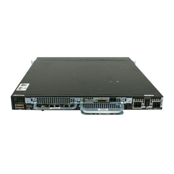
IE S Figure 1-2 Product Serial Number Location The serial number label for the Cisco AS5350XM universal gateway is located on the rear of the chassis, on the right side. (See Cisco AS5350XM Universal Gateway Chassis Installation Guide Cisco AS5350XM Universal Gateway Front Panel... -
Page 23: Cisco Product Identification Tool
Overview Figure 1-3 Note The serial number for the Cisco AS5350XM universal gateway is 11 characters long. Cisco Product Identification Tool The Cisco Product Identification (CPI) tool provides detailed illustrations and descriptions showing where to locate serial number labels on Cisco products. It includes the following features: •... -
Page 24: Power Supply
Power Supply For details on cards, installation, and troubleshooting, see the Cisco AS5350XM and Cisco AS5400XM Note Universal Gateways Card Installation Guide. This document is available on Cisco.com. (See the “Obtaining Documentation” section on page Power Supply The power system consists of a single input AC or DC power supply or a dual input (redundant) AC or DC power supply. - Page 25 Asynchronous serial (RJ-45) See the Regulatory Compliance and Safety Information document that shipped with your universal gateway. This document is available on Cisco.com. (See the section on page Cisco AS5350XM Universal Gateway Chassis Installation Guide Chassis Specifications “Obtaining Documentation” xiv.)
- Page 26 Chapter 1 Overview Chassis Specifications Cisco AS5350XM Universal Gateway Chassis Installation Guide OL-6417-02...
-
Page 27: Chapter 2 Preparing To Install The Cisco As5350Xm Universal Gateway
Preparing to Install the Cisco AS5350XM Universal Gateway This chapter describes the tasks you must perform before you begin to install the Cisco AS5350XM universal gateway and includes the following sections: Safety Recommendations, page 2-1 • • Required Tools and Equipment, page 2-3 Preparing to Connect to a Network, page 2-3 •... -
Page 28: Preventing Electrostatic Discharge Damage
For safety, periodically check the resistance value of the antistatic strap, which should be between 1 and Caution 10 megohm (Mohm). Cisco AS5350XM Universal Gateway Chassis Installation Guide Chapter 2 Preparing to Install the Cisco AS5350XM Universal Gateway OL-6417-02... -
Page 29: Required Tools And Equipment
To comply with the intra-building lightning surge requirements of GR-1089-CORE, Issue III, October 2002, you must use a shielded cable when connecting to either of the Cisco AS5350XM universal gateway Ethernet ports. The cable must consist of shielded cable terminated by shielded connectors on both ends, with the cable shield material tied to both connectors. -
Page 30: Ethernet Connections
Two Gigabit Ethernet (GE) RJ-45 ports are located on the rear panel of the universal gateway: GE0 and GE1 (selectable). To configure the Ethernet ports, see the Cisco AS5350XM and Cisco AS5400XM Universal Gateways Software Configuration Guide. Both ports use unshielded twisted-pair (UTP) cable and require Category 5 cable. -
Page 31: 2T Serial Ports
2T Serial Ports Two high-speed 12-in-1 serial ports on the rear panel of the Cisco AS5350XM universal gateway provide backhaul WAN and IP support. The following types of serial interface standards (in DTE or DCE devices) are supported: EIA/TIA-232 •... -
Page 32: Power Supply Considerations
Removable DC connector. (A label near the power inlets indicates the correct voltage, current draw, • and power dissipation for the unit.) Double-hole grounding lug for reliable grounding to the chassis. • Cisco AS5350XM Universal Gateway Chassis Installation Guide Chapter 2 Preparing to Install the Cisco AS5350XM Universal Gateway OL-6417-02... -
Page 33: Installing The Cisco As5350Xm Universal Gateway
Installing the Cisco AS5350XM Universal Gateway This chapter guides you through the installation of the Cisco AS5350XM universal gateway and includes the following sections: Setting Up the Chassis, page 3-1 • • Connecting to the Network, page 3-6 Connecting to the Console and Auxiliary Ports, page 3-11 •... -
Page 34: Setting The Chassis On A Desktop
Remove the wax paper from the bottom of each rubber foot and press the foot into the small depression Step 2 on the bottom of the chassis. (See Cisco AS5350XM Universal Gateway Chassis Installation Guide Chapter 3 3-1.) The rubber feet are included in the accessory kit that shipped with your universal Figure 3-1.) -
Page 35: C H A P T E R 3 Installing The Cisco As5350Xm Universal Gateway
Before working on a chassis or working near power supplies, unplug the power cord on AC units; disconnect the power at the circuit breaker on DC units. Statement 12 OL-6417-02 Attaching the Rubber Feet Universal gateway chassis bottom 3-2). Cisco AS5350XM Universal Gateway Chassis Installation Guide Setting Up the Chassis... - Page 36 Figure 3-3 Note: The second bracket attaches to the other side of the chassis. The chassis can also be installed with the rear panel forward. Cisco AS5350XM Universal Gateway Chassis Installation Guide Chapter 3 Standard Rack-Mount Brackets Bracket for 23-inch rack Figure 3-3.)
- Page 37 Connect the other end of the ground wire to a suitable grounding point at your site. Step 4 OL-6417-02 Figure 3-4.) Attaching the Chassis to a 19-Inch Rack—Rear Panel Forward Figure 3-5.) Use a medium flat-blade screwdriver and the Cisco AS5350XM Universal Gateway Chassis Installation Guide Setting Up the Chassis Figure 3-4.)
-
Page 38: Connecting To The Network
The Cisco AS5350XM universal gateway arrives with all carrier cards and DFCs already installed, Note unless you order a card separately as a spare. See the Cisco AS5350XM and Cisco AS5400XM Universal Gateways Card Installation Guide for card installation instructions. This document is available on Cisco.com. -
Page 39: Connecting To A Wan
To comply with the intra-building lightning surge requirements of GR-1089-CORE, Issue III, October Caution 2002, you must use a shielded cable when connecting to either of the Cisco AS5350XM universal gateway Ethernet ports. The cable must consist of shielded cable terminated by shielded connectors on both ends, with the cable shield material tied to both connectors. - Page 40 Use software commands to choose a specific port and the line termination on that port. For information Note about software commands, see the Cisco AS5350XM and Cisco AS5400XM Universal Gateways Software Configuration Guide. This document is available on Cisco.com. (See the Documentation”...
- Page 41 The customer equipment has circuitry that may have telecommunications network voltages on them. Statement 90 Figure 3-9 OL-6417-02 Figure 3-10.) Connecting a 2-Port or 4-Port DFC to an RJ-45 Jack E1 cable Cisco AS5350XM Universal Gateway Chassis Installation Guide Connecting to the Network RJ-45 jack...
- Page 42 Figure 3-11.) Figure 3-11 Synchronous serial port (DB-26) Serial transition cable Cisco AS5350XM Universal Gateway Chassis Installation Guide 3-10 Chapter 3 Connecting an 8-Port DFC to an RJ-45 Jack connector E1 cable Connecting to a CSU/DSU other DCE or DTE EIA/TIA-232, EIA/TIA-449, EIA/TIA-530A, EIA/TIA-530, V.35, or X.21 connector...
-
Page 43: Connecting To The Console And Auxiliary Ports
Configure your terminal or PC terminal emulation software for 9600 baud, 8 data bits, no parity, and 2 stop bits. Step 3 Configure the console port. See the Cisco AS5350XM and Cisco AS5400XM Universal Gateways Software Configuration Guide. This document is available on Cisco.com. (See the Documentation” section on page... -
Page 44: Connecting A Modem To The Auxiliary Port
The adapter provided is labeled MODEM. The adapter and the rollover cable are included in the accessory kit that comes with the universal gateway. (See Make sure that your modem and the auxiliary port on the Cisco AS5350XM universal gateway Note are configured for the same transmission speed (38400 baud is typical) and hardware flow control with Data Carrier Detect (DCD) and Data Terminal Ready (DTR) operations. -
Page 45: Connecting An Alarm To The Alarm Port
Note The alarm connector is a 3-wire connector that plugs into a receptacle in the rear of the chassis. The connector is provided in the accessory kit that ships with the Cisco AS5350XM universal gateway. Step 1 Insert the 3-pin alarm port connector (included in the accessory kit) into the alarm port terminal block. -
Page 46: Connecting The Ac Power Cord
The redundant AC power supply has a non-standard connector. Use the electrical power cord that Note came with your universal gateway. Connect one end of the AC power cord to the power connector on the rear panel of the Cisco AS5350XM Step 1 universal gateway (See Connect the other end of the AC power cord to the power outlet. -
Page 47: Wiring The Dc Power Supply
The internal power supply fan should power up. Wiring the DC Power Supply If you ordered the Cisco AS5350XM universal gateway with a DC power supply, follow the procedure in this section to wire the terminal block. The grounding architecture for the Cisco AS5350XM universal gateway is isolated DC return (DC-I). - Page 48 The proper wiring sequence is ground to ground, positive to positive, and negative to negative. Note that the ground wire should always be connected first and disconnected last. Statement 197 Cisco AS5350XM Universal Gateway Chassis Installation Guide 3-16 Chapter 3...
- Page 49 DC Power Supply Connections—Redundant Power Supply To DC source DC connector A - A + B - B + Source B - RTN Source A - RTN Source B - NEG Cisco AS5350XM Universal Gateway Chassis Installation Guide Supplying Power Power switch Ground 3-17...
-
Page 50: Where To Go Next
Where to Go Next Where to Go Next When you power up the Cisco AS5350XM universal gateway for the first time, messages begin to appear on your console screen. See the Cisco AS5350XM and Cisco AS5400XM Universal Gateways Software Configuration Guide for configuration instructions. This document is available on Cisco.com. (See the “Obtaining Documentation”... -
Page 51: Leds
Getting Help, page 4-10 LEDs The LEDs indicate the current operating condition of the Cisco AS5350XM universal gateway. You can observe the LEDs, note any fault condition that the product is encountering, and then contact your system administrator or a customer service representative (see the... -
Page 52: Monitoring The Environment
BITS Monitoring the Environment The Cisco AS5350XM universal gateway contains temperature sensors to detect abnormal temperature conditions during system operation. The three levels of sensor detection are as follows: If the operating temperature of the system exceeds 45°C (104°F), the system reaches a warning state. -
Page 53: Displaying The Environment Status
Temperature State: Temperature is in warning state. Fans temperature delta is measured as 6C. All fans are running well. Redundant Power System is present. RPS Input Voltage status: normal Cisco AS5350XM Universal Gateway Chassis Installation Guide Monitoring the Environment Slot 3... - Page 54 The display below appears on your console when the system reaches a shutdown state: • Router# show environment Temperature: Fans: Power Supply: Cisco AS5350XM Universal Gateway Chassis Installation Guide RPS Output Voltage status: normal RPS Fan status: normal RPS Thermal status: normal RPS OverVoltage status: normal Temperature:sensor failed.
-
Page 55: Troubleshooting Network Interfaces
Troubleshooting Environmental monitor experienced the following events: Troubleshooting Network Interfaces For information about isolating problems with the network connections to your Cisco AS5350XM universal gateway, see the Internetwork Troubleshooting Guide publication available on Cisco.com. For more information, see the section... - Page 56 Grasp the edge of the fan tray near the two end-screws and carefully pull it towards you. (See Step 4 Figure 4-5.) The fan tray power connector disconnects from its receptacle. (See Cisco AS5350XM Universal Gateway Chassis Installation Guide Cisco AS5350XM Front Panel Loosen Fan Tray Screws Chapter 4...
- Page 57 Slide the metal tabs located at the other end of the fan tray out of their slots. (See Step 5 OL-6417-02 Pulling the Edge of the Fan Tray Fan Tray Power Connector Disconnecting from the Receptacle Cisco AS5350XM Universal Gateway Chassis Installation Guide Replacing the Fan Tray Figure 4-7.)
-
Page 58: Installing The Fan Tray
Insert the metal tabs located at the end of the fan tray into their slots. (See Figure 4-8.) Use your left hand to hold that end of the fan tray against the chassis to ensure that the metal tabs do not slip out of their slots. Cisco AS5350XM Universal Gateway Chassis Installation Guide OL-6417-02... - Page 59 (See Figure 4-9 OL-6417-02 Inserting the Metal Tabs into the Slots Tabs Sliding the Fan Tray Power Connector into the Receptacle Cisco AS5350XM Universal Gateway Chassis Installation Guide Replacing the Fan Tray Figure 4-9.)
-
Page 60: Getting Help
Step 4 Figure 4-10 Getting Help For information about technical support, onsite service, and exchange and repair services, see the “Obtaining Technical Assistance” section on page Cisco AS5350XM Universal Gateway Chassis Installation Guide 4-10 Tightening Fan Tray Screws xvii. Chapter 4... -
Page 61: Appendix
Replacing Memory Components This appendix contains procedures on how to replace memory components in the Cisco AS5350XM universal gateway field-replaceable units. The appendix contains the following sections: Removing the Chassis Cover, page A-1 • Replacing the Compact Flash, page A-4 •... -
Page 62: Chassis Cover Removal
Place the gateway so that the front panel is facing you. Step 3 Remove the five screws on the chassis cover, as shown in Step 4 Cisco AS5350XM Universal Gateway Chassis Installation Guide Appendix A Replacing Memory Components Figure A-1. - Page 63 A-2, and pull it away from the tabs on the rear of the chassis. Figure A-2 Front panel OL-6417-02 Removing the Chassis Cover Screws Removing the Chassis Cover Chassis cover Cisco AS5350XM Universal Gateway Chassis Installation Guide Removing the Chassis Cover Chassis bottom...
-
Page 64: Replacing The Compact Flash
Remove the chassis cover. (See the instructions in the Step 4 page A-1.) Locate the compact flash on the system board. (See Step 5 Cisco AS5350XM Universal Gateway Chassis Installation Guide Appendix A Replacing Memory Components “Removing the Chassis Cover” section on Figure A-3.) -
Page 65: Replacing The Compact Flash
Replacing Memory Components Figure A-3 Backplane connector BITS port 2T serial interface 11 DIMM slot OL-6417-02 Memory Locations 10 Compact flash 12 32-bit PCI interface Cisco AS5350XM Universal Gateway Chassis Installation Guide Replacing the Compact Flash System board DFC connector Alarm port... -
Page 66: Replacing Dimms
Replacing DIMMs This section describes how to replace a DIMM on the Cisco AS5350XM universal gateway. The universal gateway has a single DIMM (see double data rate (DDR1) SDRAM DIMM. - Page 67 Position the new DIMM so that the polarization notch is located at the right end of the DIMM socket. Step 7 OL-6417-02 to locate the DIMM you are replacing. Removing and Replacing the DIMM Cisco AS5350XM Universal Gateway Chassis Installation Guide Replacing DIMMs “Removing the Chassis Cover” section on...
-
Page 68: Replacing The Chassis Cover
This section describes the procedure for replacing the chassis cover. Required Tools and Equipment Medium Phillips screwdriver • Five screws • Cisco AS5350XM Universal Gateway Chassis Installation Guide Inserting the New DIMM into the Socket “Replacing the Chassis Cover” section on page Appendix A Replacing Memory Components A-8.) -
Page 69: Chassis Cover Replacement
The chassis cover side tabs on both sides fit inside the chassis side panels so that they are not • exposed. When the chassis cover is properly assembled, no tabs are visible. (See OL-6417-02 Replacing the Chassis Cover Chassis cover Cisco AS5350XM Universal Gateway Chassis Installation Guide Replacing the Chassis Cover Figure A-6.) Chassis bottom Figure A-7.) - Page 70 Reconnect the AC power cord to the power supply. Step 8 Power up the universal gateway. The internal power supply fan should power up. Cisco AS5350XM Universal Gateway Chassis Installation Guide A-10 Cisco AS5350XM Chassis Appendix A Replacing Memory Components...
-
Page 71: Appendix
Replacing the Power Supply This appendix includes information on how to replace the power supply for the Cisco AS5350XM universal gateway and contains the following sections: Safety Recommendations, page B-1 • Required Tools and Equipment, page B-2 • • Removing the Chassis Cover, page B-2 Removing the Old Power Supply, page B-6 •... -
Page 72: Required Tools And Equipment
Step 2 Step d. Before performing any of the following procedures, ensure that power is removed from the DC circuit. Warning Statement 1003 Cisco AS5350XM Universal Gateway Chassis Installation Guide Appendix B Replacing the Power Supply Figure B-1 Figure B-2... -
Page 73: Appendix B Replacing The Power Supply
Figure B-1 DC Power Supply Connections—Single Power Supply Power switch To DC source DC connector Source A - NEG Ground Source B - RTN Source A - RTN Source B - NEG Cisco AS5350XM Universal Gateway Chassis Installation Guide OL-6417-02... - Page 74 Place the universal gateway so that the front panel is facing you. Step 5 Remove the five screws on the chassis cover. (See Cisco AS5350XM Universal Gateway Chassis Installation Guide DC Power Supply Connections—Redundant Power Supply To DC source DC connector...
- Page 75 Front panel Step 7 Continue with the OL-6417-02 Removing the Chassis Cover Screws Removing the Chassis Cover Chassis cover “Removing the Old Power Supply” section on page Cisco AS5350XM Universal Gateway Chassis Installation Guide Removing the Chassis Cover Chassis bottom B-6.
-
Page 76: Removing The Old Power Supply
Although the following illustrations show only the AC power supply, the procedures are the Note same for the DC power supply. Figure B-5 Power supply Cisco AS5350XM Universal Gateway Chassis Installation Guide Removing the Mounting Screw on the Single AC Power Supply Mounting screw Appendix B... - Page 77 Note other to the system board. (See OL-6417-02 Removing the Mounting Screw on the Redundant AC Power Supply Figure B-7.) Removing the Air Separator Figure B-8.) Cisco AS5350XM Universal Gateway Chassis Installation Guide Removing the Old Power Supply Chassis bottom...
-
Page 78: Removing The Old Power Supply
Slide the power supply toward the front panel to disengage the power supply from the chassis hooks. Step 6 (See Figure B-10.) Remove the power supply from the chassis. Cisco AS5350XM Universal Gateway Chassis Installation Guide Power Supply Connectors Backplane connector System board... -
Page 79: Installing The Power Supply
AC and DC power supplies. OL-6417-02 Lifting the Power Supply Out of the Chassis Power supply Figure B-11, and then slide it toward the rear panel. You will be able Cisco AS5350XM Universal Gateway Chassis Installation Guide Installing the Power Supply Chassis bottom... - Page 80 Replace the air separator, holding all cables to the right of the separator as you slip it into the chassis. Step 3 (See Figure B-13.) Cisco AS5350XM Universal Gateway Chassis Installation Guide B-10 Inserting the Power Supply in the Chassis Reconnecting the Power Cables to the Backplane Appendix B...
-
Page 81: Replacing The Chassis Cover
Hold the chassis cover over the chassis bottom, and align each of the cover tabs with the chassis tabs at Step 2 the top rear of the chassis, as shown in OL-6417-02 Replacing the Air Separator Figure B-14. Cisco AS5350XM Universal Gateway Chassis Installation Guide Replacing the Chassis Cover Chassis bottom “Replacing the Chassis Cover” section on B-11... - Page 82 Figure B-17 Reinstall the chassis on a rack, desktop, or table. Step 6 Reinstall all interface cables. Step 7 Cisco AS5350XM Universal Gateway Chassis Installation Guide B-12 Replacing the Chassis Cover Chassis cover Figure B-15 Power Ratings Label for DC Power Supply...
- Page 83 Source B - NEG Connect the DC connector to the rear of the power supply. Do not overtorque the terminal block contact screws. The recommended torque is 4.5 lb-in (0.50 N-m). Caution Cisco AS5350XM Universal Gateway Chassis Installation Guide B-13 OL-6417-02...
- Page 84 Insert the –48 VDC wires into the DC negative connectors (–) and tighten the locking screws. Ensure that no bare wire is exposed. Cisco AS5350XM Universal Gateway Chassis Installation Guide B-14 Connecting DC Power Supply—Redundant Power Supply...
- Page 85 ON position. Statement 8 Power up the universal gateway. Step 9 The internal power supply fan should power up. Cisco AS5350XM Universal Gateway Chassis Installation Guide B-15 OL-6417-02...
- Page 86 Appendix B Replacing the Power Supply Replacing the Chassis Cover Cisco AS5350XM Universal Gateway Chassis Installation Guide B-16 OL-6417-02...
-
Page 87: Appendix
This appendix provides cabling information for chassis connections only. For cabling information for Note the Cisco AS5350XM dial feature cards, see the Cisco AS5350XM and Cisco AS5400XM Universal Gateways Card Installation Guide. This appendix specifies pinouts only for the pins used. Pins not listed in the tables in this appendix are Note not connected. -
Page 88: Identifying A Rollover Cable
(See your cable was purchased from Cisco Systems, pin 1 will be white on one connector, and pin 8 will be white on the other connector (a rollover cable reverses pins 1 and 8, 2 and 7, 3 and 6, and 4 and 5). -
Page 89: Appendix C Cabling Specification
RJ-45-to-DB-25 adapter (labeled TERMINAL) Console Port Signaling and Cabling Using a DB-25 Adapter RJ-45-to-RJ-45 Rollover Cable RJ-45 Pin RJ-45 Pin Cisco AS5350XM Universal Gateway Chassis Installation Guide Console and Auxiliary Port Cables and Pinouts RJ-45-to-DB-9 Terminal Adapter Console Device DB-9 Pin... -
Page 90: Auxiliary Port Cables And Pinouts
To comply with the intra-building lightning surge requirements of GR-1089-CORE, Issue III, October Caution 2002, you must use a shielded cable when connecting to either of the Cisco AS5350XM universal gateway Ethernet ports. The cable must consist of shielded cable terminated by shielded connectors on both ends, with the cable shield material tied to both connectors. -
Page 91: Bits Port Pinouts
10/100BASE-T Port Pinouts (continued) Description – – RXD– – – BITS Port Pinouts Description BITS signal Ground Alarm Port Pinouts Description Normally open Pole Normally closed Bantam Jack Port Pinouts Description Ring Cisco AS5350XM Universal Gateway Chassis Installation Guide BITS Port Pinouts... - Page 92 Appendix C Cabling Specifications Bantam Jack Port Pinouts Cisco AS5350XM Universal Gateway Chassis Installation Guide OL-6417-02...
-
Page 93: I N D E X
Cisco AS5350 ground lug attachment (figure) Cisco AS5350 overview compact flash, replacing connecting a modem to the auxiliary port connecting a modem to the auxiliary port (figure) Cisco AS5350XM Universal Gateway Chassis Installation Guide I N D E X 3-13 viii A-1, B-2... -
Page 94: Console Port Cables And Pinouts
DB-25 adapter (table) console port signaling and cabling using a DB-9 adapter (table) conventions, document viii Cisco AS5350XM Universal Gateway Chassis Installation Guide IN-2 3-13 DC power supply 3-12 wiring DC power supply connections (figure) - Page 95 B-10 installing the power supply 3-17 interface options, LAN and WAN Cisco AS5350XM Universal Gateway Chassis Installation Guide B-11 A-9, B-12 Receptacle 4-10 4-10 Index B-10...
- Page 96 Network Connections Ethernet network connections network interfaces, troubleshooting noise level specification note symbol, meaning of viii Cisco AS5350XM Universal Gateway Chassis Installation Guide IN-4 opening the chassis opening the fan tray (figure) operating temperature organization (table) organization, document overview, Cisco AS5350...
- Page 97 Console Port Signaling and Cabling Using a DB-25 Console Port Signaling and Cabling using a DB-9 Organization technical support temperature, monitoring temperature specification tightening fan tray screws (figure) Cisco AS5350XM Universal Gateway Chassis Installation Guide 4-10 viii viii viii viii Adapter...
- Page 98 Tools Required for installation troubleshooting troubleshooting, using LEDs troubleshooting network interfaces WAN connections WAN connection to RJ-45c (figure) WAN interface options weight, Cisco AS5350 chassis wiring, DC power supply 3-15 Cisco AS5350XM Universal Gateway Chassis Installation Guide IN-6 OL-6417-02...