Casio DT-X200 Service Manual
Handheld terminal
Hide thumbs
Also See for DT-X200:
- User manual (72 pages) ,
- User manual (19 pages) ,
- Software manual (207 pages)

Related Manuals for Casio DT-X200


Summary of Contents for Casio DT-X200
- Page 1 SERVICE MANUAL HANDHELD TERMINAL DT-X200 APR. 2015 DT-X8 (For China Only) APR. 2015 Ver. 4 : Jun. 2017...
- Page 2 • Microsoft and Windows are either registered trademarks or trademarks of Microsoft Corporation in the United States and/or other countries. Information in this document is subject to change without advance notice. CASIO Computer Co., Ltd. makes no representations or warranties with respect to the contents or use of this manual and specifi cally disclaims...
-
Page 3: Table Of Contents
DT-X200/DT-X8 CONTENTS SAFETY PRECAUTIONS ....................1 GENERAL ..........................5 1-1. Confi guration by Model ......................5 1-2. Options ...........................5 SPECIFICATION ........................6 2-1. System Requirements ......................6 2-2. Part Name ..........................13 TECHNICAL INFORMATION ....................15 3-1. Wiring Diagram ........................15 3-2. System Diagram ........................16 RESET OPERATION ......................17 4-1. -
Page 4: Safety Precautions
SAFETY PRECAUTIONS Congratulations upon your selection of this CASIO product. Be sure to read the following Safety Precautions before trying to use it for the fi rst time. Your neglect or avoidance of the warning and caution statements in the subsequent pages causes the danger of fi... - Page 5 Dust and Moisture • Though the Handheld Terminal is dust and water splash resistant, its options including the battery pack are not. Keep loose metal objects and containers fi lled with liquid away from your Handheld Terminal and the options. Also, never handle the Handheld Terminal and the options while your hands are wet.
- Page 6 Immediately rinse it off with clean tap water and then consult a physician. • Replace only with the same type of battery pack recommended by CASIO. Dispose of used battery packs according to the local regulation.
- Page 7 Dust built up between the prongs can lead to the danger of fi re. Backup Copies of All Important Data • Note that CASIO Computer Co., Ltd. shall not be held liable to you or any third party for any damages or loss caused by deletion or corruption of data due to use of the Handheld Terminal, malfunction or repair of the Handheld Terminal or its peripherals, or due to the batteries going dead.
-
Page 8: General
DT-X200/DT-X8 1. GENERAL 1-1. Confi guration by Model Product Name Scanner W-LAN Remarks DT-X200-10E IEEE 802.11a/b/g/n DT-X200-20E IEEE 802.11a/b/g/n DT-X200-11E IEEE 802.11a/b/g/n DT-X200-21E IEEE 802.11a/b/g/n DT-X200-41E Full Range IEEE 802.11a/b/g/n DT-X8-10C-CNV IEEE 802.11a/b/g/n China ... -
Page 9: Specification
DT-X200/DT-X8 2. SPECIFICATION 2-1. System Requirements Item Specifi cations ® Marvell PXA320 806MHz ® ® Microsoft Windows Embedded Compact7 Memory 256MB FlashROM 512MB (User area: 300MB) 1D Laser model Frontage Straight 7 degree Wavelength 645 ~ 664nm Optical Output 1mW or less No. - Page 10 DT-X200/DT-X8 Item Specifi cations 2D Scanner Readable UPC-A/UPC-E/EAN8(JAN8)/EAN13(JAN13)/Codabar(NW-7)/ model Symbologies Code39Interleaved2of5(ITF)/MSI/Code93/ (1D) Code128(GS1-128(EAN128))/Code11/ GS1 DataBar Omnidirectional(RSS-14)/ GS1 DataBar Limited(RSSLimited)/ GS1 DataBar Expanded(RSS Expanded)/ Code32/GS1 DataBar Truncated(RSS-14 Truncated)/ISBT Readable PDF417/Micro PDF/Composite/Codablock F/ Symbologies GS1 DataBar Stacked Omnidirectional (RSS-14 Stacked Omnidirectional)/ (2D Stacked)
- Page 11 DT-X200/DT-X8 Item Specifi cations Display System Display Size 2.7 inch No. of Dots 240 (horizontal) × 320 (vertical) (QVGA) Dot Pitch 0.171 mm (vertical) × 0.171 mm (horizontal) Gradation 65,536 colors Display Font Scalable font Backlight LED backlight View Angle...
- Page 12 DT-X200/DT-X8 Item Specifi cations WLAN Output 802.11a: Max. 14Mbps 802.11b: Max. 20Mbps 802.11g: Max. 15Mbps 802.11n: Max. 14Mbps Other Function Roaming among multiple access points * Depends on access point Security Security: WEP(64/128bit)/WPA/WPA2WPA Encryption scheme: TKIP/AES Authentication method: PSK/EAP-TLS/PEAP-MSCHAP-V2 ®...
- Page 13 DT-X200/DT-X8 Item Specifi cations Communication Protocol Standards Supported Operation-check confi rmed IC ISO14443 Type A MIFARE Standard/MIFARE Ultralight JICSAP ISO14443 Type B * Before introducing, prior confi rmation of card is required as some cards may be out of ISO standard.
- Page 14 DT-X200/DT-X8 < > Power Item Specifi cations Remarks Main Battery Lithium ion battery Standard/Large-capacity Backup Battery Rechargeable lithium battery × 1 Built-in type Operating Time Standard Battery Pack • CPU speed setting - Laser model: Approx. 10 hours = Automatic power saving mode * Normal temperature - 2D model: Approx.
- Page 15 Approx. 32mm (Display) (Display) Approx. 57mm (Grip) Approx. 57mm (Grip) DT-X200-10E/11E/20E/21E DT-X8-10C-CNV/20C-CNV Approx. 44mm Approx. 32mm (Display) Approx. 35mm (Grip) DT-X200-41E < > Weight Approx. 280g (DT-X200-10E/20E/DT-X8-10C-CNV) Approx. 285g (DT-X200-11E/21E/DT-X8-20C-CNV) Approx. 295g (DT-X200-41E) * Including lithium-ion battery pack. — 12 —...
-
Page 16: Part Name
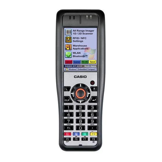
DT-X200/DT-X8 2-2. Part Name Left Front Right Back Bottom — 13 —... - Page 17 Lights red when there is a bar code scanning error and lights green when a bar code scans successfully. Lights red when the alarm function is activated. Flashes magenta when the DT-X200 is ready to communicate. Screen The screen displays texts, operations, indicators and so forth.
-
Page 18: Technical Information
DT-X200/DT-X8 3. TECHNICAL INFORMATION 3-1. Wiring Diagram FPC-PY052-FRIMDL Laser Scaner 2D Imager Full Range Imager Full Range (Decoder) Imager (Module) 12pin 30pin 14pin FPC-PY052-NFCANT FPC-PY052VA-LS or Speaker FPC-PY052VA-2D or FPC-PY052VA-FRI COM-LED CHG-LED WLAN-Antenna WLAN-Antenna CN24 61pin PWB-PY052-NFC CN16 IC86 FPC-PY052-NFC... -
Page 19: System Diagram
DT-X200/DT-X8 3-2. System Diagram DT-X200 IEEE802.11a/b/g/n DT-X8 Products Access Point IEEE802.11b/g Module Bluetooth Products Printer Access Point Bluetooth Module (Ver2.0+EDR) TEL/Cellphone USB Terminal USB Client USB Cradle (Host/Client) HA-K60IO AC Adaptor USB Prodect AD-S15050B-N5 USB Host USB Client Ethernet Cradle... -
Page 20: Reset Operation
DT-X200/DT-X8 4. RESET When a power on factor occurs, resume or reset is used to start the system. A reset clears program execution status. Therefore, data on the RAM in work is discarded, because there is a possibility that in the middle of writing a fi le is corrupt, you need to be careful. Resume, will return to the program execution state before power OFF. -
Page 21: User Disk Clear
DT-X200/DT-X8 4-4. User Disk Clear Press the Reset button for a period of one second or longer while the Fn key, CLR key, and the period key are pressed. Full reset and similar warning screen appears. Operation is also the same. Root disk (¥, ¥ Windows folder, etc.) and the registry, is initialized to the factory default state. -
Page 22: Hardware Test/Setting
DT-X200/DT-X8 5. HARDWARE TEST/SETTING 5-1. General In this chapter, how to check the hardware of DT-X200/DT-X8 is explained. The general fl ow to start up the test program is as follows: Prepare equipment required. Obtain the test program Diag_dtx200-x8.zip (Download from website.) Unzip Diag_dtx200-x8.zip and copy it to a MicroSD card. -
Page 23: Test Equipment
RFID tag (85×54 mm) microSD Card WLAN access point (IEEE802.11b/g) Recommendation : Cisco 1231G Opponent DT-X200/DT-X8 (For testing Bluetooth) Test Object DT-X200/DT-X8 USB Memory USB and Charging Unit (HA-K65US) Ethernet Cradle (HA-K62IO) USB Cable AC Adaptor for Ethernet Cradle AC Adaptor for... -
Page 24: Installing The Test Program
WLANTest.exe \DIAG\WLAN(11a) 11aWLANTest.exe, FLCE.exe, FLCE (Shortcut), wlancfg1.ini, wlancfg2.ini, wlancfg3.ini, wlancfg4.ini, wlancfg5.ini, wlancfg6.ini, wlancfg7.ini, wlancfg8.ini 2. Copy the unzipped above folders to the root directory of the microSD card (for both test object DT-X200/DT-X8 and opponent DT-X200/DT-X8). – 21 –... - Page 25 DT-X200/DT-X8 5-3-3. Installing the microSD card Install the microSD card in which the test program is written in both test object DT-X200/DT-X8 and opponent DT-X200/DT-X8. 5-3-4. Copying the test program to the FlashDisk 1. Using Explorer, select “SetFactoryTool” under \\My Device\SD Card.
-
Page 26: Function Test
Press the numeric key of DT-X200/DT-X8, or click the targeted menu on the screen. To move to the next menu screen Press the cursor key “>” of DT-X200/DT-X8, or click “[>] -> Next MENU” on the screen. To return to the previous menu screen Press the cursor key “<”... - Page 27 DT-X200/DT-X8 Menu screen transition diagram: The following shows the menu transition diagram when “[1] All Test” is selected in the Top menu. When “[1] All Test” is selected, all test items are shown. When “[2] Test limited to model (Auto judge)” is selected, individual ID is displayed at the title part and test items dedicated to that model are shown.
- Page 28 Ethernet Cradle, USB Cradle I/F(USB-Client) OS Ap Cable, AC Adaptor, Test PC W-LAN OS Ap W-LAN access point Bluetooth Class2 BTServer.exe Opponent DT-X200/DT- OS Ap (Communication) BTLineTest.exe Voltage Low Voltage Detection Test P All Test MENU-3 measurement Current Run Mode Current...
- Page 29 IDSET_PY-052 under tool has been started up. \\My Device\FlashDisk\DIAG. Enter the barcode serial number (individual ID) written on the back side of DT-X200/DT-X8. Note: Enter only the rightmost 14 digits of the written number. 14 digits (to be continued) “Enter”...
- Page 30 DT-X200/DT-X8 2. Laser Calibration (*1D Laser model only) Note: When the MAIN-UNIT or LASER-UNIT is replaced with a new one, carry out this calibration before testing “Laser Barcode Read”. Operation Display Test Details “ ” Calibration is executed Select [7].Laser Calibration automatically.
- Page 31 DT-X200/DT-X8 5-4-5. Function test 1. RAM Operation Display Test Details “ ” The increment data is written to, Select [1].RAM from All Test read from and then compared with MENU-1 screen. the maximum possible RAM area. If OK: The screen returns to the Menu screen.
- Page 32 DT-X200/DT-X8 4. ADC-Sensor Operation Display Test Details “ Judges automatically if the AD- Select [9].ADC-Sensor” from converted value is within the All Test MENU-4 screen. following range or not for each item. Main battery voltage (ON) (MUX0): 3.0 to 4.3 [V] Main battery voltage (OFF) (MUX1): 3.0 to 4.3 [V]...
- Page 33 Failure. 7. Battery Cover SW (Standard) Operation Display Test Details “ DT-X200/DT-X8 detects the Select [6].Battery Cover SW removal of battery cover, and then (Standard)” from All Test MENU- the next screen appears. 1 screen.
- Page 34 DT-X200/DT-X8 8. Touch Panel Operation Display Test Details “ Press down the cursors at 4 corners Select [7].Touch Panel” from (painted portions) with the stylus in All Test MENU-1 screen. any order. The pressed cursors disappear. After touching all cursors, the...
- Page 35 DT-X200/DT-X8 10. LCD Operation Test Details “ Pressing the “Enter” key changes the pattern screens Select [3].LCD” from All Test MENU-2 in sequence. screen. After 8 pattern screens are displayed, judgment screen is displayed. If the patterns are displayed correctly: Press the “1”...
- Page 36 DT-X200/DT-X8 11. LCD Backlight Operation Display Test Details “ The backlight brightness is Select [4].LCD Backlight” from maximized. All Test MENU-2 screen. Press the “Enter” key. The backlight brightness is minimized. Press the “Enter” key. The backlight brightness is set to a standard level.
- Page 37 DT-X200/DT-X8 12. Operation LED Operation Display Test Details “ Indicator 2 (the right side LED) Select [6].Operation LED” from Indicator 2 lights in red and the whole screen All Test MENU-2 screen. is displayed in red. Press the “Enter” key.
- Page 38 DT-X200/DT-X8 13. Charge LED (USB) Operation Display Test Details “ Check that the Indicator 1 (the Set DT-X200/DT-X8 to left side LED) lights in orange or and Charging Unit” and connect yellow. the USB cable. The judgment screen appears. Note:...
- Page 39 DT-X200/DT-X8 16. Audio (Rec & Rep) Operation Display Test Details “ Sound input from the DT-X200/DT- Select [4].Audio(Rec&Rep)” X8 microphone is output from the from All Test MENU-3 screen. speaker. Talk over the DT-X200/DT-X8 The judgment screen appears. microphone. If sound is output (OK): Press the “1”...
- Page 40 DT-X200/DT-X8 19. 2D Scanner Dust Check Note: This test is not required for the Full Range model. Operation Display Test Details Select “[8].2D Scanner Dust Check if any foreign substances Check” from All Test MENU-3 are included in the captured screen.
- Page 41 DT-X200/DT-X8 21. Full Range Imager I/F (UART) Operation Display Test Details “ Imager module version check is Select [5].Full Range Imager carried out to see whether the (UART)” from All Test MENU-7 version is correct or not. screen. If OK: The screen returns to the Menu screen.
- Page 42 No howling occurs (OK): screen. Press the “OK” button on the screen. The screen returns to the Note: Menu screen. Place DT-X200/DT-X8 with LCD facing up. Howling occurs (Failure): Press the “Retry” button on the screen. Take an action according to the retry results.
- Page 43 The NFC fi rmware version is with a distance of 50 mm from automatically checked and, when DT-X200/DT-X8 and select “[3]. the result is OK, DT-X200/DT-X8 NFC Tag ID Read” from All Test starts to access to the tag. MENU-7 screen.
- Page 44 *1: Depends on the OS to be used. (ActiveSync: for Windows XP or earlier, Windows Mobile Device Center: for Windows Vista or later) 2. Operation Check that the communication between the PC and DT-X200/DT-X8 is properly established using Microsoft ActiveSync/Windows Mobile Device Center. For details, refer to “Quick Start Guide”.
- Page 45 Test Details “ “ The Indicator 2 (on the right side Select Settings” - Control of DT-X200/DT-X8) starts fl ashing “ Panel” - WLANPower”. in orange. Check the checkbox “WLAN Power Enable” and click “OK” to supply power to the integrated WLAN module.
- Page 46 Explorer. Select one from the “BT Test Server A to F”. The communication distance between DT- X200/DT-X8s should be within 3 m. Test target DT-X200/ The opposing DT-X200/ DT-X8: DT-X8 is automatically Start up “BTLineTest” detected. under \\My Device\...
- Page 47 Adjust the DC power supply so If XINHIN0 is generated (Failure): that the DC voltmeter reads 3.9 V. An error indication is displayed. DT-X200/DT-X8 is turned ON. -> Pressing the “Enter” key returns you to the Menu screen. – 44 –...
- Page 48 DT-X200/DT-X8 5-4-8. Current measurement 1. Run Mode Current 1. Preparation (1) Open the Battery Cover and remove the battery pack. (2) Connect equipment as shown below. (3) Set the voltage control of the DC power supply at minimum position and turn ON the power.
- Page 49 DT-X200/DT-X8 3. Laser Current Use the same measurement connection as described in “1. Run Mode Current ” Operation Display Test Details Adjust the DC power supply so Check if the current value is within that the DC voltmeter reads 3.9 V.
- Page 50 DT-X200/DT-X8 6. Full Range Imager Current Use the same measurement connection as described in “1. Run Mode Current ” Operation Display Test Details Adjust the DC power supply so Check if the current value is within that the DC voltmeter reads 3.9 420 to 520 mA.
-
Page 51: Disassembly And Reassembly
DT-X200/DT-X8 6. DISASSEMBLY AND REASSEMBLY Note: ▪ When reassembling the parts, reverse the disassembly procedures. If “note(s) on reassembling” is stated, be sure to follow it. ▪ Use the right screwdriver according to the screw diameter. ▪ When disassembling or reassembling parts, do not pinch or damage wires. -
Page 52: Lower-Case-Unit
DT-X200/DT-X8 6-1. LOWER-CASE-UNIT (1) Removing the LOWER-CASE-UNIT 1. Set the Lock Switches (2 pcs.) to the “FREE” position by turning them. 2. Remove the Battery Cover. 3. Remove the Battery Pack from the main body. 4. Rmove the microSD Card from the main body. - Page 53 DT-X200/DT-X8 7. Remove the screws S1 (2 pcs.) and detach the SUP-LOCK. Screws S1 SUP-LOCK Note on reassembling: Note on reassembling: Align the concave portions of the Do not make a crease on the FPC. FPC with the ribs of the case.
-
Page 54: Upper-Case-Unit
DT-X200/DT-X8 3. Remove the screw S1 (1 pce) and then detach the NFC-ANTENNA. Note: NFC-ANTENNA is fi xed with a double-face tape. Double-face Tape Screw S1 NFC-ANTENNA 6-2. UPPER-CASE-UNIT (1) Removing the UPPER-CASE-UNIT 1. Peel off the tapes (2 pcs.), unlock the connector locks, and then remove the FPCs (2 pcs.). - Page 55 DT-X200/DT-X8 4. Remove the UPPER-CASE-UNIT, paying attention to the FPC. UPPER-CASE-UNIT INNER-CASE-UNIT Note: • During repair work, be sure to cover the inner surface of the Touch Panel with the FILM/TP (protective fi lm) to protect from dirt and scratches.
-
Page 56: Inner-Case-Unit
DT-X200/DT-X8 6-3. INNER-CASE-UNIT 6-3-1. 1D LASER / 2D SCANNER MODEL (1) Removing the 1D Laser or 2D Scanner 1. Remove the screws (2 pcs.) and detach the SCANNER-UNIT. 1D Laser model 2D Scanner model Screws Screws 2. 1D Laser model: Peel off... - Page 57 DT-X200/DT-X8 (2) Removing the NFC-UNIT (NFC type) 1. Peel off the tape, unlock the connector lock, and remove the FPC. 2. Remove the screws S1 (2 pcs.) and detach the NFC-UNIT. Screws S1 NFC-UNIT (3) Removing the SBAT-UNIT 1. Remove the screws S1 (3 pcs.) and detach the SBAT-SPACER.
- Page 58 DT-X200/DT-X8 (4) Removing the EXT-UNIT 1. Remove the CAP-UNIT PCB. 2. Remove the screws S1 (1 pce.) and S7 (4 pcs.). Screws S7 Screw S1 3. Remove the SBAT-HOLDER while paying attention to the antennas (2 places). Note: Gently lift the SBAT-HOLDER as the antennas are connected to it.
- Page 59 DT-X200/DT-X8 4. Disconnect the connector and antenna. Antenna Connector 5. Remove the EXT-UNIT. SBAT-HOLDER EXT-UNIT EXT-UNIT Note on reassembling: • When the EXT-UNIT is replaced with a new one, form its shape as shown below. • Attach the antenna to the position shown below.
- Page 60 DT-X200/DT-X8 6-3-2. FULL RANGE IMAGER MODEL (1) Removing the SBAT-UNIT 1. Remove the screws S1 (3 pcs.) and detach the SBAT-SPACER. 2. Peel off the tape. 3. Disconnect the SBAT-UNIT connector to remove the SBAT-UNIT. Note: SBAT-UNIT is fi xed with a double-face tape.
- Page 61 DT-X200/DT-X8 2. Peel off the tape, unlock the connector lock, and remove the FPC. 3. Remove the screws S1 (2 pcs.) and detach the NFC-UNIT. Screws S1 NFC-UNIT (3) Removing the FRI-ASSY & EXT-UNIT 1. Remove the CAP-UNIT PCB. 2. Remove the screw S1 (1 pce.).
- Page 62 DT-X200/DT-X8 Note on reassembling: Antenna Note on reassembling: Put the excess part in the groove of the I-CASE. 5. Disconnect the connector and antenna. Note: Gently lift the SBAT-HOLDER as the antenna and FPC are connected to it. Antenna Connector FRI-ASSY 6.
- Page 63 DT-X200/DT-X8 • Attach the antenna to the position shown below. Antenna 7. Peel off the tape, unlock the connector lock, and remove the FPC. Connector FRI-ASSY Note on reassembling: • When replacing the FRI-ASSY, peel off the lens protective fi lm and attach the SPACER-FRI.
- Page 64 DT-X200/DT-X8 6-3-3. All MODEL (1) Removing the MAIN-PCB 1. Remove the screws S7 (2 pcs.). 2. Peel off the tape, unlock the connector lock, and remove the FPC. 3. Disconnect the Antenna Cable. Antenna Cable Screws S7 Note on reassembling: •...
- Page 65 DT-X200/DT-X8 4. Peel off the tape, unlock the connector lock, and remove the FPC. 5. Peel off the tape, and remove the MAIN-PCB. Tape Note on reassembling: • After installing the MAIN-PCB, fi x it with tape. Tape • HEAT-SHEET-B (Full Range Imager model) When the MAIN-PCB is replaced with a new one, attach the HEAT-SHEET-B.
- Page 66 DT-X200/DT-X8 6. Peel off the tape, unlock the connector lock, and remove the FPC. 7. Remove the TR-IC-UNIT. 8. NFC type Peel off the tape, unlock the connector lock, and remove the FPC. (NFC type) MAIN-PCB TR-IC-UNIT (2) Removing the SCANNER-UNIT 1.
- Page 67 DT-X200/DT-X8 (3) Removing the LCD-UNIT 1. Peel off the TAPE/LCD. 2. Remove the LCD-UNIT. 3. Remove the COIL-SPRINGs (4 pcs.). COIL-SPRINGs Tape/LCD Notes on reassembling: • Be sure that four COIL-SPRINGs are mounted on the case. • Pass the FPC of the LCD into the groove of the I-CASE.
- Page 68 DT-X200/DT-X8 (4) Removing the I-CASE, VIBRATION-MOTOR, LAN-ANT-UNIT 1. Remove the VIBRATION-MOTOR. 2. Remove the LAN-ANT-UNIT. I-CASE Note: LAN-ANT-UNIT is fi xed with a double-face tape. VIBRATION-MOTOR LAN-ANT-UNIT Notes on reassembling: • When the I-CASE is to be replaced, the following parts should be mounted on the I-CASE as they are not included in.
- Page 69 DT-X200/DT-X8 • LAN-ANT-UNIT Pass the coaxial cable into the hole of the I-CASE. • VIBRATION-MOTOR After installation, be sure that it is not inclining. – 66 –...
-
Page 70: Exploded View / Parts List
The numbers in the item column correspond to the same numbers in exploded view. MARKS: Q: Quantity used per unit R: Rank A: Essential B: Stock recommended C: Less recommended X: No stock recommended Refer the latest "Parts Price Code" at "PARTS FINDER" on the Casio Service WEB site (https://www.servicecasio.com). — 67 —... -
Page 71: Exploded View
DT-X200/DT-X8 7-1. EXPLODED VIEW 7-1-1. FINAL-ASSY / LABELS 10 UPPER-CASE-UNIT INNER-CASE-UNIT LASER 11 LOWER-CASE-UNIT Full Range Laser/2D LABEL/CAUTION 14-1 LABEL/RATING 14 LABEL/REVISION 13 LABEL/WINCE6.0 — 68 —... -
Page 72: Upper-Case-Unit
DT-X200/DT-X8 7-1-2. UPPER-CASE-UNIT 15-1 15-5 15-2 15-4 15-3 15-6 — 69 —... -
Page 73: Inner-Case-Unit (1D Laser / 2D Scanner Model)
DT-X200/DT-X8 7-1-3. INNER-CASE-UNIT (1D LASER / 2D SCANNER MODEL) 1D Laser model 2D Scanner model NFC type All models 2D Scanner model NFC type NFC type NFC type 32-1 1D Laser model 2D Scanner model — 70 —... -
Page 74: Inner-Case-Unit (Full Range Imager Model)
DT-X200/DT-X8 7-1-4. INNER-CASE-UNIT (FULL RANGE IMAGER MODEL) NFC type 92 FRI (FRI-ASSY) NFC type — 71 —... -
Page 75: Lower-Case-Unit
DT-X200/DT-X8 7-1-5. LOWER-CASE-UNIT NFC type NFC type Full Range Imager model — 72 —... -
Page 76: Bundled Items / Tools
DT-X200/DT-X8 7-1-6. BUNDLED ITEMS / TOOLS — 73 —... -
Page 77: Parts List
DT-X200/DT-X8 7-2. PARTS LIST 1 DT-X200-10E 3 DT-X200-20E 5 DT-X200-41E 6 DT-X8-10C-CNV 2 DT-X200-11E 4 DT-X200-21E 7 DT-X8-20C-CNV Q'ty Item Code No. Parts Name Specification FINAL-ASSY 10385321 PACKING/SUP RJC505199-001V01 10385354 LOCK/SUP RJC505303-001V01 10500654 COVER/EXT RJC505223-002V01 10500656 PLATE/G RJC505380-006V01 10512117 COVER/BATTERY/LARGE... - Page 78 DT-X200/DT-X8 1 DT-X200-10E 3 DT-X200-20E 5 DT-X200-41E 6 DT-X8-10C-CNV 2 DT-X200-11E 4 DT-X200-21E 7 DT-X8-20C-CNV Q'ty Item Code No. Parts Name Specification UPPER-CASE-UNIT 10400632 CASE-ASSY/UPPER RJC505391*001 TK 10400633 CASE-ASSY/UPPER RJC505391*002 TK 15-1 10385315 TAPE/LED RJC505193-001V01 15-2 10385314 LENS/LED RJC505192-001V01 15-3...
- Page 79 DT-X200/DT-X8 1 DT-X200-10E 3 DT-X200-20E 5 DT-X200-41E 6 DT-X8-10C-CNV 2 DT-X200-11E 4 DT-X200-21E 7 DT-X8-20C-CNV Q'ty Item Code No. Parts Name Specification 10394354 EXT-UNIT RJC505404*001 TK 10530599 WLAN-UNIT/2.4G RJC507591*001 TK 10073157 BATTERY VL2330/1VC 10376933 SUBASSY/WIRE RJC505093-001V01 10289904 TAPE/DOUBLE/SBAT RJC503702-001V01 10394356...
- Page 80 DT-X200/DT-X8 1 DT-X200-10E 3 DT-X200-20E 5 DT-X200-41E 6 DT-X8-10C-CNV 2 DT-X200-11E 4 DT-X200-21E 7 DT-X8-20C-CNV Q'ty Item Code No. Parts Name Specification LOWER-CASE-UNIT 10500576 CASE-SUBASSY/LOWER RJC505172*003V05 10500582 CASE-SUBASSY/LOWER RJC506030*003V02 10500578 SUBASSY/TRIGGER/L RJC505250*003V02 10500579 SUBASSY/TRIGGER/R RJC505253*003V02 10385347 TAPE/TRIGGER RJC505256-001V01 10385374 PLATE/TRIGGER...
-
Page 81: Cradle (Ha-K60Io/K62Io)
DT-X200/DT-X8 7-3. CRADLE ( HA-K62IO/HA-K60IO 7-3-1. EXPLODED VIEW HA-K62IO MAIN UNIT: HA-K62IO CN-PANEL: HA-K60IO HA-K60IO SIDE BEZEL: HA-K62IO HA-K60IO HA-K62IO — 78 —... -
Page 82: Parts List
Notes: 1. The numbers in the item column correspond to the same numbers in exploded view. 2. MARKS: Q: Quantity used per unit R: Rank Essential Stock recommended Less recommended No stock recommended 3. Refer the latest "Parts Price Code" at "PARTS FINDER" on the Casio Service WEB site (https://www.servicecasio.com). — 79 —... -
Page 83: Usb And Charging Unit (Ha-K65Us)
DT-X200/DT-X8 7-4. USB AND CHARGING UNIT ( HA-K65US 7-4-1. EXPLODED VIEW LABEL/RATING LEVER/SWITCH — 80 —... -
Page 84: Parts List
Notes: 1. The numbers in the item column correspond to the same numbers in exploded view. 2. MARKS: Q: Quantity used per unit R: Rank Essential Stock recommended Less recommended No stock recommended 3. Refer the latest "Parts Price Code" at "PARTS FINDER" on the Casio Service WEB site (https://www.servicecasio.com). — 81 —... - Page 85 • Correction of the 7. EXPLODED VIEW / PARTS LIST (P74 and P75) Ver.4 : Jun. 2017 • Correction of the 7. EXPLODED VIEW / PARTS LIST (P74) CASIO COMPUTER CO., LTD. CS Technical Department TOKYO, JAPAN © 2015 – 2017 CASIO COMPUTER CO., LTD.