Table of Contents
Advertisement
Quick Links
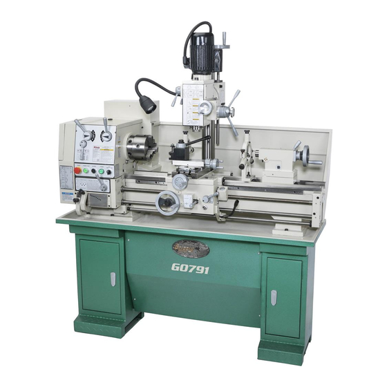
MODEL G0791
COMBINATION GUNSMITHING
LATHE/MILL
OWNER'S MANUAL
(For models manufactured since 9/15)
COPYRIGHT © MAY, 2015 BY GRIZZLY INDUSTRIAL, INC., REVISED MAY, 2017 (BL)
WARNING: NO PORTION OF THIS MANUAL MAY BE REPRODUCED IN ANY SHAPE
OR FORM WITHOUT THE WRITTEN APPROVAL OF GRIZZLY INDUSTRIAL, INC.
#WKBB17270 PRINTED IN CHINA
V2.10.17
Advertisement
Table of Contents

Related Manuals for Grizzly G0791


Summary of Contents for Grizzly G0791
- Page 1 OWNER'S MANUAL (For models manufactured since 9/15) COPYRIGHT © MAY, 2015 BY GRIZZLY INDUSTRIAL, INC., REVISED MAY, 2017 (BL) WARNING: NO PORTION OF THIS MANUAL MAY BE REPRODUCED IN ANY SHAPE OR FORM WITHOUT THE WRITTEN APPROVAL OF GRIZZLY INDUSTRIAL, INC.
-
Page 3: Table Of Contents
Table of Contents INTRODUCTION ..........3 SECTION 4: LATHE OPERATIONS ....32 Contact Info............ 3 Operation Overview ........32 Manual Accuracy ........... 3 Chuck & Faceplate Mounting....... 33 Identification ........... 4 Chuck Safety & Support Devices ....33 Controls & Components ......... 5 Chuck Installation......... - Page 4 SECTION 6: ACCESSORIES ......72 SECTION 10: PARTS ........101 Accessories ..........101 SECTION 7: MAINTENANCE ......76 Headstock Gearing ........103 Schedule ............76 Headstock Controls........105 Cleaning/Protecting ........76 Quick-Change Gearbox ......107 Lubrication ........... 77 Apron ............109 Machine Storage ..........
-
Page 5: Introduction
INTRODUCTION Contact Info Manual Accuracy Model G0791 (Mfd. Since 9/15) -
Page 6: Identification
G. Mill Vertical Travel Handwheel R. Stand Mounting Points (2 of 4) H. Fine Downfeed Handwheel S. Carriage (see Page 6 for details) Coarse Downfeed Handwheel Storage Cabinet Compound Rest Handwheel U. Quick-Change Tool Post Model G0791 (Mfd. Since 9/15) -
Page 7: Controls & Components
Inch Threading Chart: Displays the neces- sary configuration of gearbox levers and end gears for inch threading options. Figure 1. Headstock and quick-change gearbox controls. Model G0791 (Mfd. Since 9/15) - Page 8 Configuring the end gears (shown in Figure 139) controls the speed of the leadscrew for threading W. Quill Lock Lever: Secures quill in position. or the feed rod for power feed operations. X. Tailstock Lock Lever: Secures tailstock in position along bedway. Model G0791 (Mfd. Since 9/15)
- Page 9 AK. Quill Lock Bolt: Locks vertical position of AD. Z-Axis Lock Bolt: Locks vertical position of quill (or Z-axis) when tightened. Typically mill headstock when tightened. used in conjunction with spindle downfeed controls when milling. Model G0791 (Mfd. Since 9/15)
-
Page 10: Machine Data Sheet
Machine Data Sheet MACHINE DATA SHEET Customer Service #: (570) 546-9663 · To Order Call: (800) 523-4777 · Fax #: (800) 438-5901 MODEL G0791 12" X 36" COMBINATION GUNSMITHING LATHE/MILL Product Dimensions: Weight................................1345 lbs. Width (side-to-side) x Depth (front-to-back) x Height..............66 x 27-1/2 x 75 in. - Page 11 The information contained herein is deemed accurate as of 11/11/2018 and represents our most recent product specifications. Model G0791 PAGE 2 OF 4 Due to our ongoing improvement efforts, this information may not accurately describe items previously purchased. Model G0791 (Mfd. Since 9/15)
- Page 12 The information contained herein is deemed accurate as of 11/11/2018 and represents our most recent product specifications. Model G0791 PAGE 3 OF 4 Due to our ongoing improvement efforts, this information may not accurately describe items previously purchased. -10- Model G0791 (Mfd. Since 9/15)
-
Page 13: Section 1: Safety
SECTION 1: SAFETY Safety Instructions for Machinery -11- Model G0791 (Mfd. Since 9/15) - Page 14 -12- Model G0791 (Mfd. Since 9/15)
-
Page 15: Additional Safety For Metal Lathes
Additional Safety for Metal Lathes -13- Model G0791 (Mfd. Since 9/15) -
Page 16: Additional Safety For Mills
Additional Safety for Mills -14- Model G0791 (Mfd. Since 9/15) -
Page 17: Additional Lathe Chuck Safety
Additional Lathe Chuck Safety -15- Model G0791 (Mfd. Since 9/15) -
Page 18: Section 2: Power Supply
Cycle ............60 Hz Phase ............ 1-Phase Power Supply Circuit ......15 Amps Plug/Receptacle ......NEMA 6-15 Cord ..“S”-Type, 3-Wire, 14 AWG, 300 VAC Full-Load Current Rating Full-Load Current Rating at 220V ..8.5 Amps -16- Model G0791 (Mfd. Since 9/15) - Page 19 Grounding Instructions Extension Cords Figure 6. Typical 6-15 plug and receptacle. Minimum Gauge Size ......14 AWG Maximum Length (Shorter is Better)..50 ft. -17- Model G0791 (Mfd. Since 9/15)
-
Page 20: Section 3: Setup
— Shop rags — Cleaner/degreaser (see Page 20) — Quality metal protectant lubricant — Safety glasses for each person — Anchoring hardware as needed (see Page 25) — Precision level at least 12" long -18- Model G0791 (Mfd. Since 9/15) -
Page 21: Inventory
—Gear 50-tooth ......... 1 —Gear 60-tooth ......... 1 —Gear 86/91-tooth (Installed) ....1 Drill Chuck Arbor R8 x B16 ......1 W. Spindle Sleeve R8 x MT3 ......1 X. Spindle Sleeve MT5 x MT3 ......1 -19- Model G0791 (Mfd. Since 9/15) -
Page 22: Cleanup
Cleanup T23692—Orange Power Degreaser A great product for removing the waxy shipping grease from your machine during clean up. Figure 9. T23692 Orange Power Degreaser. -20- Model G0791 (Mfd. Since 9/15) -
Page 23: Site Considerations
Site Considerations Wall 30" Minimum Clearance for Maintenance Keep Workpiece ⁄ " Loading Area Unobstructed 66" Not to Scale Figure 10. Minimum working clearances. -21- Model G0791 (Mfd. Since 9/15) -
Page 24: Assembly
Unbolt lathe from shipping pallet. Attach handles to cross slide and carriage handwheels (see Figure 12). Assembling the Model G0791 consists of build- ing the stand assembly, attaching the handwheel Handwheel handles, placing and securing the lathe on the... - Page 25 11. Have another person hold onto lathe to pre- vent it from swinging as you slowly raise lathe from pallet and move it over stand. -23- Model G0791 (Mfd. Since 9/15)
- Page 26 Note: Purpose of drawbar cap is to secure drawbar without restricting its rotation. If nec- essary, loosen drawbar cap slightly until you can rotate drawbar by hand. Figure 17. Locations to secure back splash. -24- Model G0791 (Mfd. Since 9/15)
-
Page 27: Anchoring To Floor
See the figure below for an example of a high precision level offered by Grizzly. Figure 20. Popular method for anchoring machinery to a concrete floor. Figure 21. Model H2683 Master Machinist's Level. -25- Model G0791 (Mfd. Since 9/15) -
Page 28: Lubricating Lathe
Extension Cords on Page 17 for more infor- mation. Note: If this lathe was shipped with oil in the reservoirs, do not change that oil until after the test run and spindle break-in procedures. -26- Model G0791 (Mfd. Since 9/15) - Page 29 Circuit to those terminals. Requirements for 220V on Page 16. Ground Power Source Figure 23. Incoming power wires connected inside electrical cabinet. -27- Model G0791 (Mfd. Since 9/15)
-
Page 30: Test Run
(Disengaged) Cross Slide Disengaged Disengaged Carriage Halfnut Lever Feed Selection Engaged Lever Figure 24. Disengaging carriage components. Rotate Emergency Stop/RESET button clock- wise so it pops out. Power lamp on control panel should illuminate. -28- Model G0791 (Mfd. Since 9/15) - Page 31 Push Emergency Stop/RESET button to turn 2300 lathe OFF, then, without resetting Emergency Stop/RESET button, try to restart spindle rotation, as instructed in Step 7. Spindle Figure 26. Mill spindle speed set to 250 RPM. should not start. -29- Model G0791 (Mfd. Since 9/15)
-
Page 32: Spindle Break-In
Run lathe spindle at 70 RPM for 10 minutes in each direction (first forward, then reverse). Turn lathe OFF. Move lathe spindle speed levers to C and 1 for 200 RPM, then run lathe for 5 minutes in each direction. -30- Model G0791 (Mfd. Since 9/15) -
Page 33: Recommended Adjustments
(refer to Lubrication on Page 77). DO NOT attempt to change mill spindle speed while spindle is in motion. Doing so can cause catastrophic damage to mill headstock gears and components. -31- Model G0791 (Mfd. Since 9/15) -
Page 34: Section 4: Lathe Operations
10. Uses carriage handwheels or power feed options to move tooling into workpiece for operations. 11. When finished cutting, moves spindle lever to OFF position, waits for spindle to completely stop, then removes workpiece. -32- Model G0791 (Mfd. Since 9/15) -
Page 35: Chuck & Faceplate Mounting
Chuck & Faceplate Chuck Safety & Mounting Support Devices Figure 27. Examples of common devices used during chuck installation and removal. -33- Model G0791 (Mfd. Since 9/15) -
Page 36: Chuck Installation
Chuck Installation Figure 29. Cam line positioned between the "V" marks after the camlocks are fully tightened. Figure 28. Inserting camlock studs into spindle cam holes. Figure 30. Correcting an improperly installed stud. -34- Model G0791 (Mfd. Since 9/15) -
Page 37: Chuck Removal
Chuck Removal Registration Marks Figure 32. Camlock is fully loosened when the cam line is aligned with the spindle mark. Figure 31. Registration mark locations. -35- Model G0791 (Mfd. Since 9/15) -
Page 38: Scroll Chuck Clamping
Scroll Chuck Chuck Jaw Reversal Clamping Figure 34. Reversing the chuck jaws. Figure 33. Jaw selection and workpiece holding. -36- Model G0791 (Mfd. Since 9/15) -
Page 39: 4-Jaw Chuck
4-Jaw Chuck Figure 35. 4-jaw tightening sequence. Figure 36. Example of a non-cylindrical workpiece correctly mounted on a 4-jaw chuck. -37- Model G0791 (Mfd. Since 9/15) -
Page 40: Faceplate
Faceplate Non-Cylindrical Workpiece Clamp Faceplate Figure 37. Generic picture of workpiece clamped in a faceplate. -38- Model G0791 (Mfd. Since 9/15) -
Page 41: Tailstock
Using Quill Tailstock Lock Quill Lock Lever Lever ⁄ " Square Drive Quill Handwheel Lock-Down Figure 38. Tailstock and quill lock levers in locked position. -39- Model G0791 (Mfd. Since 9/15) - Page 42 Figure 39. Types of tapered arbors and tooling. Tang Removing Tooling Figure 40. Example photos of inserting tools with tangs into the tailstock. Drift Key Slot Figure 41. Drift key slot in the side of the quill. -40- Model G0791 (Mfd. Since 9/15)
- Page 43 Precision Level ..........1 (1 of 2) Offset Indicator Figure 42. Left offset adjustment. Tools Needed Hex Wrench 4mm ..........1 Figure 44. Turning a dead center. Figure 43. Set screw adjustment in relation to tailstock movement. -41- Model G0791 (Mfd. Since 9/15)
- Page 44 Figure 45. Example of stock mounted between Figure 46. Adjust tailstock toward the operator. centers on a typical lathe. Figure 47. Adjust tailstock away from the operator. -42- Model G0791 (Mfd. Since 9/15)
-
Page 45: Centers
Adapter Dead Live Sleeve Center Center Carbide-Tipped Dead Center Figure 48. Adapter sleeve and centers. Dead Centers Dead Center Lathe Figure 49. Example of using a dead center with a faceplate and lathe dog. -43- Model G0791 (Mfd. Since 9/15) - Page 46 Dead Center Removing Center from Tailstock Figure 50. Example of using a carbide-tipped dead center installed in the tailstock. Drift Key Slot Figure 51. Typical drift key slot in the side of a quill. -44- Model G0791 (Mfd. Since 9/15)
-
Page 47: Joining Drill Chuck & Arbor
Joining Drill Chuck Mounting Workpiece Between Centers & Arbor Figure 52. Example of a workpiece mounted between centers on a typical lathe. Figure 53. Tapping drill chuck/arbor on block of wood to seat it. -45- Model G0791 (Mfd. Since 9/15) -
Page 48: Steady Rest
Note: To reduce the effects of friction, lubri- required to properly support workpiece, then cate the finger rollers with way oil before tighten hex nut shown in Figure 54 to secure operation. it in place. -46- Model G0791 (Mfd. Since 9/15) -
Page 49: Follow Rest
Tools Needed Hex Wrench 3mm ..........1 Hex Wrench 6mm ..........1 Carriage Lock Cross Slide Compound Rest Lock Lock Figure 57. Locations of compound rest, carriage, and cross slide locks. -47- Model G0791 (Mfd. Since 9/15) -
Page 50: Tool Post
Hex Wrench Size 5mm ........1 Location For Reference Mark Figure 59. Using an angle gauge to set compound rest to 60° for threading. Tool Post Figure 60. Example of tool mounted in tool post. -48- Model G0791 (Mfd. Since 9/15) - Page 51 Steel Shims ........As Needed Cutting Tool ............1 Fine Ruler ............1 Tailstock Center ..........1 Figure 61. Cutting tool aligned with spindle centerline (viewed from tailstock). Figure 62. Cutting tool aligned to the tailstock center. -49- Model G0791 (Mfd. Since 9/15)
-
Page 52: Spider
Use this handwheel to move the cutting tool lin- early along the set angle of the compound rest. The compound rest has an indirect-read gradu- ated dial, which shows the actual distance the tool moves. -50- Model G0791 (Mfd. Since 9/15) -
Page 53: Spindle Speed
Figure 65. Spindle speed formula for lathes. BEFORE moving the spindle speed levers. The chart below shows the various combinations of lever positions for achieving a desired speed. Spindle Speed RPM 1400 1000 Figure 67. Spindle speed chart. -51- Model G0791 (Mfd. Since 9/15) -
Page 54: Understanding Gear Charts
Feed Chart—Displays gearbox dial positions for different speeds of automatic feed (power feed) Figure 68. Setting the spindle speed to 600 used with turning operations (see Figure 70). RPM. Figure 70. Feed rate chart. -52- Model G0791 (Mfd. Since 9/15) - Page 55 Figure 73. Available feed rates and end gear positions for feeding. Figure 71. Metric threading chart. Inch Threading Chart—Displays headstock end gear and gearbox lever positions used for cutting various inch threads (see Figure 72). Figure 72. Inch threading chart. -53- Model G0791 (Mfd. Since 9/15)
- Page 56 Figure 77 shows how the gearing illustrations in the thread chart relate to the end gears. Figure 75. Feed levers set to "B" and "7" for 0.0096 in/rev. longitudinal feed rate. Figure 77. Power feed gearing setup. -54- Model G0791 (Mfd. Since 9/15)
-
Page 57: Power Feed
Threading on Page 61. If feed selection lever and half nut are engaged at the same time, machine damage could occur. Even though there is a lock- out device to prevent this, it could break if forced. -55- Model G0791 (Mfd. Since 9/15) - Page 58 Figure 79. Headstock and quick-change gearbox controls for power feed. Note: When using this lever, you may need to slightly rotate the handwheel of the com- ponent you are trying to engage, so that the apron gears can mesh. -56- Model G0791 (Mfd. Since 9/15)
- Page 59 Page 58 for detailed instructions). Note: The top half of the chart displays feed rates in mm/rev., while the bottom half dis- plays feed rates in in./rev. Figure 83. Example of gearbox lever pins seated in holes. -57- Model G0791 (Mfd. Since 9/15)
-
Page 60: End Gears
Figure 84. End gear configuration for power feeding and inch threading. Mesh the 40T "F" position gear with the 86T change gear, and mesh it with the 40T "G" posi- tion gear in the "inside" position. -58- Model G0791 (Mfd. Since 9/15) - Page 61 Figure 86. Secondary metric threading end gear 86T/91T configuration. Change Gear With 91T Gear Toward Lathe 45T Gear In "F" Position 2.25 Metric Thread Pitch 60T Gear In "G" Position Figure 87. Configuring end gears for 2.25 metric thread pitch. -59- Model G0791 (Mfd. Since 9/15)
- Page 62 Note: Make sure the keys stay inserted in the shafts as you slide the F and G gears off. 10. Re-install end gear cover. -60- Model G0791 (Mfd. Since 9/15)
-
Page 63: Threading
"5" Feed Selection Half Nut Lever Lever Disengaged Cross Slide Disengaged Carriage Halfnut Lever Feed Selection Engaged Lever Figure 90. Apron threading controls. Figure 89. End gear and gearbox lever configuration for 11 TPI. -61- Model G0791 (Mfd. Since 9/15) - Page 64 1–8 returns the carriage for the next pass and re- engages the half nut using the same thread dial Figure 93. Thread dial chart. setting to resume the cut as in the previous pass. -62- Model G0791 (Mfd. Since 9/15)
- Page 65 (see the example in Figure 95). SCALE SCALE SCALE 1, 3 1, 3 Figure 95. 1 or 3 line on dial for threading odd TPI. SCALE SCALE -63- Model G0791 (Mfd. Since 9/15)
-
Page 66: Section 5: Mill Operations
Connects machine to power and turns it ON. Uses downfeed controls or cross slide table controls to perform cutting operation. 10. Turns machine OFF and waits for spindle to completely stop before removing workpiece. -64- Model G0791 (Mfd. Since 9/15) -
Page 67: Removing Compound Rest
Remove compound rest, then remove second T-bolt from rear T-slot in cross-slide table (see Figure 98). T-Slot T-Slots Cross Slide With T-Bolts Table Removed Figure 100. Compound rest installed. Figure 98. Compound rest and T-bolts removed. -65- Model G0791 (Mfd. Since 9/15) -
Page 68: Downfeed Controls
The fine downfeed graduated dial measures spin- dle movement in 0.002" increments, with one full revolution equaling 0.092" of spindle travel. -66- Model G0791 (Mfd. Since 9/15) -
Page 69: Headstock Movement
Z-Axis Lock wise 0.010". Bolts (1 of 2) Tighten quill lock bolt. Turn mill/drill ON and perform cutting pass. Figure 102. Mill Z-axis controls. Re-tighten Z-axis lock bolts. -67- Model G0791 (Mfd. Since 9/15) - Page 70 The cross slide table travels in the X-axis (lon- gitudinal), and the Y-axis (cross) directions, as illustrated in Figure 104. X-Axis or Longitudinal Travel (Left & Right) Y-Axis or Cross Travel (In & Out) Figure 104. Cross slide travel directions. -68- Model G0791 (Mfd. Since 9/15)
-
Page 71: Installing/Removing Tooling
It can also use MT#3 or MT#2 DISCONNECT MACHINE FROM POWER! tooling with the included adapter sleeves. Verify drawbar is installed correctly (refer to The Model G0791 includes the following spindle Page 24). tools (see Figure 106): Align tool alignment slot (see Figure 106) A. - Page 72 Tap top of drawbar with hammer to unseat tightening drawbar. taper (see Figure 109). Figure 109. Example of tapping drawbar to unseat tool taper. Hold onto tooling with one hand and fully unthread drawbar. -70- Model G0791 (Mfd. Since 9/15)
-
Page 73: Spindle Speed
These sources will help you take into Figure 112. Mill spindle speed controls set for account the applicable variables in order to deter- 250 RPM. mine the best spindle speed for the operation. -71- Model G0791 (Mfd. Since 9/15) -
Page 74: Section 6: Accessories
The Model T25250 set fits 3/8" T-slots and includes 5/16"-18 studs. Racks can be bolted to the wall or side of machine for easy access. T10556—Taper Attachment Kit for G0791 This taper attachment provides precision outside and inside tapers up to 12" without having to off- set the tailstock. - Page 75 Figure 118. T24512 6-Piece Center Drill Set. G7154—Premium Milling Vise-5" G7156—Premium Milling Vise-4" These swiveling milling vises feature perfectly aligned, precision-ground jaws, robust clamping screws, and easy-to-read 0°–360° scales. Figure 117. T10720 Crown Savers. Figure 119. Premium milling vises. -73- Model G0791 (Mfd. Since 9/15)
- Page 76 3 directions: vertical, hori- zontal, and angular, as required for proper perfor- mance of any floating reamer. Figure 122. T10667 Bald Eagle Reamer Holder MT#3. Figure 124. Model T24798 Angle Plate Set, 2 -74- Model G0791 (Mfd. Since 9/15)
- Page 77 Figure 128. T25615 Milling for Home Machinists. Figure 126. T24803 1" Dial Indicator & Small Magnetic Base. -75- Model G0791 (Mfd. Since 9/15)
-
Page 78: Section 7: Maintenance
(especially • Ensure carriage lock bolt is loose. parts that are exposed to water-soluble cutting fluid). Use way oil to prevent corrosion (see Page 75 for an offering from Grizzly). -76- Model G0791 (Mfd. Since 9/15) -
Page 79: Lubrication
Headstock Daily Quick-Change Gearbox Daily Headstock Apron Daily Oil Type ..Grizzly T23963 or ISO 32 Equivalent Bedways Daily Oil Amount .......... 3.5 Quarts Longitudinal Leadscrew Daily Check/Add Frequency ......... Daily Ball Oilers Daily Change Frequency ....... - Page 80 Quick-Change Gearbox Adding Oil The oil fill plug is located on top of the headstock, Oil Type ..Grizzly T23962 or ISO 68 Equivalent as shown in Figure 130. Oil Amount ......2 Pumps Each Port Check/Add Frequency ......... Daily...
- Page 81 Bedways Changing Oil & Flushing Reservoir Small metal particles may accumulate at the bot- Oil Type ..Grizzly T23962 or ISO 68 Equivalent tom of the reservoir with normal use. Therefore, to Oil Amount ......... As Needed keep the reservoir clean, drain and flush it at least Lubrication Frequency .........
- Page 82 Ball Oilers Oil Type ..Grizzly T23963 or ISO 32 Equivalent Oil Amount ........1 or 2 Squirts Lubrication Frequency ......... Daily This lathe has 11 ball oilers, as shown in Figures 135–138. Ball Oilers Proper lubrication of ball oilers is done with a pump-type oil can fitted with a tip wide enough to seal the ball oiler inlet.
- Page 83 End Gears Using a clean brush, apply a thin layer of grease on gears. Make sure to get grease Grease ..Grizzly T23964 or NLGI#2 Equivalent between gear teeth, but do not fill teeth Frequency ....Annually or When Changing valleys.
-
Page 84: Machine Storage
Loosen or remove V-belts so they do not become stretched during storage period. (Be sure to place a maintenance note near power button as a reminder that the belts have been loosened or removed.) -82- Model G0791 (Mfd. Since 9/15) -
Page 85: Section 8: Service
2. Spindle speed or feed rate wrong for Handbook or feed/speed calculator on the internet. down under load. cutting operation. 3. Cutting tool is dull. 3. Sharpen or replace the cutting tool. -83- Model G0791 (Mfd. Since 9/15) - Page 86 8. Gears broken. 8. Replace gears. Gear change levers 1. Gears not aligned inside headstock/quick- 1. Rotate spindle by hand with light pressure on the will not shift. change gearbox. lever until gear falls into place. -84- Model G0791 (Mfd. Since 9/15)
- Page 87 1. Increase return spring tension. return to highest 2. Worn return spring. 2. Replace return spring. position. Mill FWD/REV 1. Shorted/disconnected wiring. 1. Inspect circuit boards, wiring connections. Replace/ switch does not repair as necessary. work. -85- Model G0791 (Mfd. Since 9/15)
-
Page 88: Adjusting Backlash
Loosen set screws on compound rest face- plate several turns (see Figure 143). Faceplate Screws Cap Screw Securing Leadscrew Nut to Cross Slide Figure 141. Location of cap screw that secures the leadscrew nut. Figure 143. Compound rest backlash adjustments. -86- Model G0791 (Mfd. Since 9/15) -
Page 89: Adjusting Gib
⁄ turn. yet the handwheels are still easy to move. After each adjustment, use cross slide handwheel to test cross slide movement. Repeat Steps 3–4 until cross slide move- ment is acceptable. -87- Model G0791 (Mfd. Since 9/15) - Page 90 —To tighten carriage gib, tighten set screws. —To loosen gib, loosen set screws. Repeat adjustments as necessary until adjustment is acceptable. Hold set screws in place and tighten jam nuts. Figure 146. Location of carriage lock. -88- Model G0791 (Mfd. Since 9/15)
-
Page 91: Adjusting Half Nut
It should not feel too stiff or too loose. Repeat Steps 3–5, if necessary, until you are satisfied with half nut adjustment, then re-install thread dial. -89- Model G0791 (Mfd. Since 9/15) -
Page 92: Installing/Removing Gap Insert
(2 of 4) Tension belts (refer to Tensioning/Replacing V-Belt on the previous page.) Figure 151. Gap retaining fasteners. Secure end gear cover. Tighten dowel pin jack nuts (see Figure 151) to draw pins from gap. -90- Model G0791 (Mfd. Since 9/15) -
Page 93: Adjusting Spindle Bearing Preload
DISCONNECT MACHINE FROM POWER! until they just contact gap. Tighten preload cap screw until it contacts headstock and resistance can be felt, then tighten it an additional ⁄ -turn. -91- Model G0791 (Mfd. Since 9/15) - Page 94 (see Figure 155) and remove it. Spanner Wrench Figure 157. Dial indicator setup. Outer Spanner Nut 10. Move carriage an additional 0.100" toward headstock. Figure 155. Loosening outer spanner nut. -92- Model G0791 (Mfd. Since 9/15)
- Page 95 —If spindle nose is too hot to touch, preload is too tight and you must repeat bear- ing preload adjustment procedure. When repeating procedure, rotate inner spanner nut a little less during Step 12 in preceding instructions. -93- Model G0791 (Mfd. Since 9/15)
-
Page 96: Section 9: Wiring
SECTION 9: WIRING machine Wiring Safety Instructions -94- Model G0791 (Mfd. Since 9/15) -
Page 97: Wiring Overview
(Page 99) (Page 99) To Control Panel To Lathe Motor (Page 100) (Page 98) To Electrical Cabinet (Page 96) To Spindle Switch (Page 100) 6-15 Plug (As Recommended) Ground READ ELECTRICAL SAFETY -95- Model G0791 (Mfd. Since 9/15) ON PAGE 94! -
Page 98: Electrical Cabinet Wiring Diagram
1U1 1U2 PE PE Work Lamp Mill Motor Lathe Motor Control Panel Power Connection Spindle Switch Page 99 Page 99 Page 95 Page 100 Page 95 Page 100 READ ELECTRICAL SAFETY -96- Model G0791 (Mfd. Since 9/15) ON PAGE 94! - Page 99 Electrical Cabinet Wiring Figure 160. Electrical cabinet wiring. READ ELECTRICAL SAFETY -97- Model G0791 (Mfd. Since 9/15) ON PAGE 94!
-
Page 100: Lathe Motor Wiring Diagram
Lathe Motor Wiring Diagram To Electrical Cabinet Motor 220V Page 96 Capacitor 20MFD 450VAC Z2W2 Z1W1 Ground Start Capacitor 150MFD 250VAC Figure 161. Lathe motor wiring. READ ELECTRICAL SAFETY -98- Model G0791 (Mfd. Since 9/15) ON PAGE 94! -
Page 101: Mill Motor & Work Lamp Wiring Diagram
Figure 162. Mill motor Lamp Switch wiring. KCD1 25T8 Work Lamp Junction Box (Viewed from Behind) To Electrical Figure 163. Worklamp Figure 164. Worklamp Cabinet terminal bar. switch. Page 96 READ ELECTRICAL SAFETY -99- Model G0791 (Mfd. Since 9/15) ON PAGE 94! -
Page 102: Control Panel Wiring Diagrams
Ground Headstock To Electrical Cabinet Page 96 Figure 165. Control panel wiring. Spindle Switch Wiring Spindle Rotation Switch To Electrical Cabinet Page 96 Figure 166. Spindle switch wiring. READ ELECTRICAL SAFETY -100- Model G0791 (Mfd. Since 9/15) ON PAGE 94! -
Page 103: Section 10: Parts
SECTION 10: PARTS Accessories 36-1 36-2 36-3 -101- Model G0791 (Mfd. Since 9/15) - Page 104 WRENCH 17 X 19MM OPEN-ENDS P07910021 HEX WRENCH 2MM P07910044 WRENCH 22 X 24MM OPEN-ENDS P07910022 SPIDER BOLT W/NUT M10-1.5 X 38 P07910045 SPINDLE SLEEVE R8-MT#3 P07910023 LIVE CENTER MT#3 P07910046 SPINDLE SLEEVE MT#3-MT#2 -102- Model G0791 (Mfd. Since 9/15)
-
Page 105: Headstock Gearing
Headstock Gearing 135 164 141 140 -103- Model G0791 (Mfd. Since 9/15) - Page 106 WRENCH 17 X 19MM OPEN-ENDS P07910021 HEX WRENCH 2MM P07910044 WRENCH 22 X 24MM OPEN-ENDS P07910022 SPIDER BOLT W/NUT M10-1.5 X 38 P07910045 SPINDLE SLEEVE R8-MT#3 P07910023 LIVE CENTER MT#3 P07910046 SPINDLE SLEEVE MT#3-MT#2 -104- Model G0791 (Mfd. Since 9/15)
-
Page 107: Headstock Controls
Headstock Controls 201 202 1119 1120 1119-1 1119-2 1119-5 1119-4 1118 1120 1117 1116 1123 1119-6 1124 1109 1106 1108 1110 1108 1103 1115 1114 1110 1100 1107 1104 1101 1113 1102 1111 1112 -105- Model G0791 (Mfd. Since 9/15) - Page 108 COMBO GEAR FLAT WASHER 6MM 1120 P07911120 KNURLED KNOB M10-1.5 P07910207 COMBO GEAR 86T/91T 1123 P07911123 E-CLIP 15MM P07910208 BALL BEARING 6202ZZ 1124 P07911124 HEX NUT M10-1.5 P07910209 BUSHING 42 X 25 X 17MM -106- Model G0791 (Mfd. Since 9/15)
-
Page 109: Quick-Change Gearbox
Quick-Change Gearbox -107- Model G0791 (Mfd. Since 9/15) - Page 110 WRENCH 17 X 19MM OPEN-ENDS P07910021 HEX WRENCH 2MM P07910044 WRENCH 22 X 24MM OPEN-ENDS P07910022 SPIDER BOLT W/NUT M10-1.5 X 38 P07910045 SPINDLE SLEEVE R8-MT#3 P07910023 LIVE CENTER MT#3 P07910046 SPINDLE SLEEVE MT#3-MT#2 -108- Model G0791 (Mfd. Since 9/15)
-
Page 111: Apron
Apron 452A 451-1 419-1 420-1 430 429 -109- Model G0791 (Mfd. Since 9/15) - Page 112 WRENCH 17 X 19MM OPEN-ENDS P07910021 HEX WRENCH 2MM P07910044 WRENCH 22 X 24MM OPEN-ENDS P07910022 SPIDER BOLT W/NUT M10-1.5 X 38 P07910045 SPINDLE SLEEVE R8-MT#3 P07910023 LIVE CENTER MT#3 P07910046 SPINDLE SLEEVE MT#3-MT#2 -110- Model G0791 (Mfd. Since 9/15)
-
Page 113: Saddle & Cross Slide
Saddle & Cross Slide 513 514 -111- Model G0791 (Mfd. Since 9/15) - Page 114 WRENCH 17 X 19MM OPEN-ENDS P07910021 HEX WRENCH 2MM P07910044 WRENCH 22 X 24MM OPEN-ENDS P07910022 SPIDER BOLT W/NUT M10-1.5 X 38 P07910045 SPINDLE SLEEVE R8-MT#3 P07910023 LIVE CENTER MT#3 P07910046 SPINDLE SLEEVE MT#3-MT#2 -112- Model G0791 (Mfd. Since 9/15)
-
Page 115: Compound Rest & Tool Holder
WRENCH 17 X 19MM OPEN-ENDS P07910021 HEX WRENCH 2MM P07910044 WRENCH 22 X 24MM OPEN-ENDS P07910022 SPIDER BOLT W/NUT M10-1.5 X 38 P07910045 SPINDLE SLEEVE R8-MT#3 -113- P07910023 LIVE CENTER MT#3 P07910046 SPINDLE SLEEVE MT#3-MT#2 Model G0791 (Mfd. Since 9/15) -
Page 116: Tailstock
P07910042 CAP SCREW M8-1.25 X 16 -114- P07910020 HEX WRENCH 4MM P07910043 WRENCH 17 X 19MM OPEN-ENDS Model G0791 (Mfd. Since 9/15) P07910021 HEX WRENCH 2MM P07910044 WRENCH 22 X 24MM OPEN-ENDS P07910022 SPIDER BOLT W/NUT M10-1.5 X 38 P07910045... -
Page 117: Lathe Motor, Bed, & Stand
Lathe Motor, Bed, & Stand 806-11 806-1 806-10 806-9 806-2 806-8 806-3 806-4 806-7 806-6 806-5 836A 836-1 829-2 829A 829-2 829-1 -115- Model G0791 (Mfd. Since 9/15) - Page 118 WRENCH 17 X 19MM OPEN-ENDS P07910021 HEX WRENCH 2MM P07910044 WRENCH 22 X 24MM OPEN-ENDS P07910022 SPIDER BOLT W/NUT M10-1.5 X 38 P07910045 SPINDLE SLEEVE R8-MT#3 P07910023 LIVE CENTER MT#3 P07910046 SPINDLE SLEEVE MT#3-MT#2 -116- Model G0791 (Mfd. Since 9/15)
-
Page 119: Feed Rod
SET SCREW M6-1 X 8 P07910910 COMPRESSION SPRING 7020 P07910922 SPINDLE SWITCH ARM P07910911 SPINDLE SWITCH HANDLE M10-1.5 X 16 P07910923 SPINDLE SWITCH BOX P07910912 HANDLE BRACKET P07910924 BUTTON HD CAP SCR M4-.7 X 45 -117- Model G0791 (Mfd. Since 9/15) -
Page 120: Machine Labels & Cosmetics
WARNING! serious injury or Only trained personnel AMOUNT. 63 x 38mm ENTANGLEMENT WITHOUT WRITTEN APPROVAL! Grizzly will not accept labels changed without approval. 38 x 123.5mm force, resulting in death! should operate this machine. HAZARD! PINCH artwork changes are required, contact us immediately at manuals@grizzly.com. -
Page 121: Electrical Components
TAILSTOCK WRENCH P07910013 DRILL CHUCK KEY 5/16" STD 11T SD-5/8" P07910036 3-JAW CHUCK ASSY 6" D1-5 SCROLL -119- Model G0791 (Mfd. Since 9/15) P07910014 SCREWDRIVER PHILLIPS #2 36-1 P07910036-1 3-JAW CHUCK TOP JAW SET P07910015 SCREWDRIVER FLAT #2 36-2 P07910036-2 3-JAW CHUCK BOTTOM JAW SET... -
Page 122: Steady Rest
LIVE CENTER MT#3 P07910046 SPINDLE SLEEVE MT#3-MT#2 P07910021 HEX WRENCH 2MM P07910044 WRENCH 22 X 24MM OPEN-ENDS P07910022 SPIDER BOLT W/NUT M10-1.5 X 38 P07910045 SPINDLE SLEEVE R8-MT#3 P07910023 LIVE CENTER MT#3 P07910046 SPINDLE SLEEVE MT#3-MT#2 -120- Model G0791 (Mfd. Since 9/15) -
Page 123: Mill Headstock
WRENCH 17 X 19MM OPEN-ENDS P07910021 HEX WRENCH 2MM P07910044 WRENCH 22 X 24MM OPEN-ENDS P07910022 SPIDER BOLT W/NUT M10-1.5 X 38 P07910045 SPINDLE SLEEVE R8-MT#3 P07910023 LIVE CENTER MT#3 P07910046 SPINDLE SLEEVE MT#3-MT#2 -121- Model G0791 (Mfd. Since 9/15) - Page 124 1543 1559 1544 1560 1572 1544 1561 1573 1556 1583 1584 1582 1580 1579 1585 1577 1578 1586 1574 1575 1595 1594 1581 1593 1599 1591 1597 1598 1589 1596 1588 1592 1587 1590 -122- Model G0791 (Mfd. Since 9/15)
- Page 125 WRENCH 17 X 19MM OPEN-ENDS P07910021 HEX WRENCH 2MM P07910044 WRENCH 22 X 24MM OPEN-ENDS P07910022 SPIDER BOLT W/NUT M10-1.5 X 38 P07910045 SPINDLE SLEEVE R8-MT#3 P07910023 LIVE CENTER MT#3 P07910046 SPINDLE SLEEVE MT#3-MT#2 -123- Model G0791 (Mfd. Since 9/15)
-
Page 126: Column & Fine Downfeed
WRENCH 17 X 19MM OPEN-ENDS P07910021 HEX WRENCH 2MM P07910044 WRENCH 22 X 24MM OPEN-ENDS P07910022 SPIDER BOLT W/NUT M10-1.5 X 38 P07910045 SPINDLE SLEEVE R8-MT#3 P07910023 LIVE CENTER MT#3 P07910046 SPINDLE SLEEVE MT#3-MT#2 -124- Model G0791 (Mfd. Since 9/15) -
Page 127: Section 11: Appendix
Inch Threading Chart 1, 3 1-2-3-4 1–8 1, 3 1–8 1-2-3-4 1–8 1–8 1-2-3-4 1–8 1, 3 1–8 1–8 1–8 1-2-3-4 1–8 1, 3 1–8 1–8 1–8 1–8 1-2-3-4 1–8 1–8 1, 3 1-2-3-4 1–8 1–8 -125- Model G0791 (Mfd. Since 9/15) -
Page 131: Warranty & Returns
WARRANTY & RETURNS...