Table of Contents
Advertisement
Quick Links
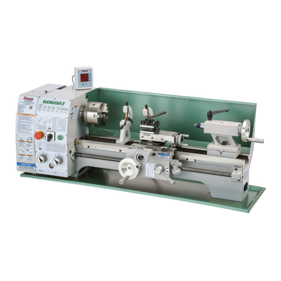
MODEL G0602Z/G0752Z
10" X 22" BENCHTOP
METAL LATHE w/DRO
MANUAL INSERT
Models G0602Z and G0752Z are identical to their non-"Z" counterparts, but the Z models are equipped
with an included X/Z-Axis DRO.
NOTE: The bed and cross slide on these models have been specially machined to mount the DRO scales.
Thus, the DRO components included with these models cannot be easily retrofitted onto Models G0602 or
G0752.
: To reduce the risk of serious injury, you MUST read and understand this insert—and
the entire Model G0602/G0752 manual—BEFORE assembling, installing, or operating this machine!
If you have any further questions about this manual insert or the differences between Model G0602
and G0602Z, or Model G0752 and G0752Z, contact our Technical Support at (570) 546-9663 or
email techsupport@grizzly.com.
Model G0602Z
Model G0752Z
COPYRIGHT © JUNE, 2017 BY GRIZZLY INDUSTRIAL, INC.
WARNING: NO PORTION OF THIS MANUAL MAY BE REPRODUCED IN ANY SHAPE
OR FORM WITHOUT THE WRITTEN APPROVAL OF GRIZZLY INDUSTRIAL, INC.
(FOR MODELS MANUFACTURED SINCE 05/17) #KB18650 PRINTED IN CHINA
Advertisement
Table of Contents

Related Manuals for Grizzly G0602Z


Summary of Contents for Grizzly G0602Z
- Page 1 METAL LATHE w/DRO MANUAL INSERT Models G0602Z and G0752Z are identical to their non-"Z" counterparts, but the Z models are equipped with an included X/Z-Axis DRO. NOTE: The bed and cross slide on these models have been specially machined to mount the DRO scales.
- Page 2 955 P0602Z955 X-AXIS SENSOR MOUNTING PLATE P0602Z967 Z-AXIS SENSOR CONNECTING PLATE 956 P0602Z956 CAP SCREW M4-.7 X 10 1001 P0602Z1001 MACHINE ID LABEL (G0602Z) 957 P0602Z957 FLAT WASHER 4MM 1001 P0752Z1001 MACHINE ID LABEL (G0752Z) 958 P0602Z958 PLASTIC SLEEVE 6 X 7 X 3D...
- Page 3 Z-axis in hundredths of a millimeter or thou- slide) and Z-axis (carriage) travel. sandths of an inch. (Included Y-axis display line is not used on G0602Z or G0752Z.) Note: When placing the DRO, locate all cables so B. "X" value displays total X-axis travel from they do not interfere with machine operation and cannot be pinched by moving components.
- Page 4 Model G0602Z/G0752Z (Mfd. Since 06/17)
- Page 5 (For models manufactured since 03/17) G0602 Shown COPYRIGHT © MARCH, 2013 BY GRIZZLY INDUSTRIAL, INC., REVISED APRIL, 2017 (JH) WARNING: NO PORTION OF THIS MANUAL MAY BE REPRODUCED IN ANY SHAPE OR FORM WITHOUT THE WRITTEN APPROVAL OF GRIZZLY INDUSTRIAL, INC.
- Page 6 This manual provides critical safety instructions on the proper setup, operation, maintenance, and service of this machine/tool. Save this document, refer to it often, and use it to instruct other operators. Failure to read, understand and follow the instructions in this manual may result in fire or serious personal injury—including amputation, electrocution, or death.
-
Page 7: Table Of Contents
Table of Contents INTRODUCTION ..........3 SECTION 4: OPERATIONS ......25 Machine Description ........3 Operation Overview ........25 Contact Info............ 3 Chuck & Faceplate Mounting....... 26 Manual Accuracy ........... 3 Installation & Removal Devices ....26 Model G0602 Identification ......4 Chuck Installation......... - Page 8 SECTION 5: ACCESSORIES ......49 SECTION 8: WIRING ........66 Wiring Safety Instructions ......66 SECTION 6: MAINTENANCE ......51 G0602 Wiring Diagram ........ 67 Schedule ............51 G0602 Electrical Components ..... 68 Ongoing ............51 G0752 Wiring Box Diagram ......69 Daily, Before Operations ........
-
Page 9: Introduction
Models G0602 and G0752 both require setting manuals and manual updates for free on our web- gearbox dial positions and positioning V-belts to site at www.grizzly.com. select the spindle speed. However, the Model G0752 features an electronic variable-speed con- Alternatively, you can call our Technical Support trol and digital RPM display that make it possible for help. -
Page 10: Model G0602 Identification
Model G0602 Identification Figure 1. G0602 identification. A. Emergency Stop Button Chip Tray B. Spindle Direction Switch M. Thread Dial C. ON Button N. Half Nut Lever D. 3-Jaw Chuck O. Cross Slide Handwheel E. Steady Rest P. Carriage Handwheel 4-Way Tool Post Q. -
Page 11: Model G0752 Identification
Model G0752 Identification Figure 2. G0752 identification. A. Emergency Stop Button M. Tailstock B. ON Button N. Back Splash C. OFF Button O. Chip Tray D. Spindle Speed RPM Display P. Thread Dial E. Spindle Speed Dial Q. Half Nut Lever Spindle Direction Switch R. -
Page 12: Controls & Components
Controls & D. OFF Button: Stops spindle rotation. Components E. Spindle Speed RPM Display: Shows a digi- tal readout of the spindle speed. Spindle Speed Dial: Controls the variable Refer to Figures 3–8 and the following descrip- spindle speed. tions to become familiar with the basic controls of this lathe. -
Page 13: Carriage
Carriage Tailstock Figure 7. Tailstock controls. Tailstock Quill Handwheel: Controls the movement of the quill. Figure 6. Carriage controls. U. Offset Scale: Indicates the relative distance of tailstock offset from the spindle centerline. 4-Way Tool Post: Holds up to four cutting tools at once that can be individually indexed V. -
Page 14: Machine Data Sheet
Customer Service #: (570) 546-9663 · To Order Call: (800) 523-4777 · Fax #: (800) 438-5901 MODEL G0602, G0752 10" x 22" Bench Top Metal Lathe Model Number G0602 G0752 Product Dimensions Weight 330 lbs. Width/Depth/Height 46" x 22" x 16 ⁄... - Page 15 Model Number G0602 G0752 Headstock Information Spindle Bore 25mm Spindle Size ⁄ " Spindle Taper MT#4 Spindle Threads 8 TPI Number of Spindle Speeds Variable Range of Spindle Speeds 150 – 2400 RPM 100 – 800, 160 – 1300, 250 – 2000 RPM Spindle Type Threaded Spindle Bearings...
-
Page 16: Section 1: Safety
SECTION 1: SAFETY For Your Own Safety, Read Instruction Manual Before Operating This Machine The purpose of safety symbols is to attract your attention to possible hazardous conditions. This manual uses a series of symbols and signal words intended to convey the level of impor- tance of the safety messages. - Page 17 WEARING PROPER APPAREL. Do not wear FORCING MACHINERY. Do not force machine. clothing, apparel or jewelry that can become It will do the job safer and better at the rate for entangled in moving parts. Always tie back or which it was designed. cover long hair.
-
Page 18: Additional Safety For Metal Lathes
Additional Safety for Metal Lathes Serious injury or death can occur from getting entangled in, crushed between, or struck by rotating parts on a lathe! Unsecured tools or workpieces that fly loose from rotating objects can also strike nearby operators with deadly force. To minimize the risk of getting hurt or killed, anyone operating this machine MUST completely heed the hazards and warnings below. -
Page 19: Glossary Of Terms
The following is a list of common definitions, terms and phrases used throughout this manual as they relate to this lathe and metalworking in general. Become familiar with these terms for assembling, adjusting or operating this machine. Your safety is VERY important to us at Grizzly! Arbor: A machine shaft that supports a cutting Lathe Center: A lathe accessory with a 60°... -
Page 20: Section 2: Power Supply
SECTION 2: POWER SUPPLY Availability Before installing the machine, consider the avail- ability and proximity of the required power supply Serious injury could occur if you connect circuit. If an existing circuit does not meet the machine to power before completing setup requirements for this machine, a new circuit must process. -
Page 21: Grounding & Plug Requirements
Grounding & Plug Requirements Improper connection of the equipment-grounding wire can result in a risk of electric shock. The This machine MUST be grounded. In the event wire with green insulation (with or without yellow of certain malfunctions or breakdowns, grounding stripes) is the equipment-grounding wire. -
Page 22: Section 3: Setup
• you are completely satisfied with the machine and • Quality Metal Protectant ..... As Needed have resolved any issues between Grizzly or the • Disposable Shop Rags ....As Needed shipping agent. You MUST have the original pack- •... -
Page 23: Inventory
Inventory Dead Center MT#4 ........1 W. Change Gear Set ........1 — Change Gear (27-tooth, Installed) ..1 — Change Gear (36-tooth) ......1 The following is a list of items shipped with your — Change Gear (40-tooth) ......1 machine. -
Page 24: Cleanup
Cleanup Gasoline and petroleum products have low flash The unpainted surfaces of your machine are points and can explode coated with a heavy-duty rust preventative that or cause fire if used to prevents corrosion during shipment and storage. clean machinery. Avo i d This rust preventative works extremely well, but it u sing t h e s e p r o du c t s will take a little time to clean. -
Page 25: Site Considerations
Site Considerations Weight Load Physical Environment Refer to the Machine Data Sheet for the weight The physical environment where the machine is of your machine. Make sure that the surface upon operated is important for safe operation and lon- which the machine is placed will bear the weight gevity of machine components. -
Page 26: Lifting & Placing
Lifting & Placing Wrap the lifting straps around the bed and between the leadscrew and the bedway, as shown in Figure 14, to help prevent bending the leadscrew during lifting. HEAVY LIFT! Straining or crushing injury may occur from improperly lifting machine or some of its parts. -
Page 27: Leveling & Mounting
See the figure below for an example of a high Flat Washer precision level. Lathe Silicon Chip Pan Workbench Flat Washer Hex Bolt Figure 16. Example of a through mount setup. Figure 15. Grizzly Model H2683 12" Master Machinist's Level. -21- Model G0602/G0752 (Mfd. Since 03/17) -
Page 28: Assembly
Assembly Power Connection With the exception of the handwheel handles, the Before the machine can be connected to the lathe is shipped fully assembled. power source, an electrical circuit and connec- tion device must be prepared per the POWER To install the handwheel handles, thread the large SUPPLY section in this manual, and all previ- handle into the carriage handwheel and the small ous setup instructions in this manual must be... - Page 29 To test run your machine: Half Nut Make sure the spindle direction switch (see Lever Figure 18) is turned to STOP, and press the emergency STOP button. Disengaged Halfnut Lever Emergency Button Stop Button Engaged Spindle Direction Switch Figure 19. Half nut lever in the disengaged Pointing to STOP position.
-
Page 30: Spindle Break-In
Spindle Break-In Recommended Adjustments Before subjecting the lathe to full loads, it is essen- tial to complete the spindle break-in process. This For your convenience, the adjustments listed will ensure the best results and maximum life of below have been performed at the factory. the precision components inside the lathe. -
Page 31: Section 4: Operations
Regardless of the content in this sec- tion, Grizzly Industrial will not be held liable for accidents caused by lack of training. Complete the Test Run & Break-In proce- dure on Pages 22– 24 before using this lathe for any cutting or threading operations;... -
Page 32: Chuck & Faceplate Mounting
Chuck & Faceplate Installation & Mounting Removal Devices This lathe is equipped with a threaded spindle Because chucks are heavy and often awkward to nose. With this type of spindle, a chuck or face- hold, some kind of support or protective device plate is screwed directly onto the spindle nose. -
Page 33: Chuck Installation
Chuck Installation Insert the chuck wrenches as shown in Figure 22, and tighten the chuck until it is seated snug against the spindle shoulder. To ensure accurate work, it is extremely important to make sure the spindle nose and chuck mating surfaces are clean. -
Page 34: Chuck Removal
Chuck Removal Changing Jaw Set Tools Needed: Tools Needed: Chuck Wrenches ..........2 Chuck Wrench ........... 1 Hex Wrench 5mm ..........1 The 3-jaw scroll chuck included with the lathe fea- To remove the chuck: tures inside and outside hardened steel jaw sets (see Figure 26), which move in unison to center DISCONNECT LATHE FROM POWER! a concentric workpiece. -
Page 35: Scroll Chuck Clamping
Scroll Chuck To change the jaw set: Clamping DISCONNECT LATHE FROM POWER! Place a piece of plywood over the bedways to protect them from potential damage. The 3-jaw scroll-type chuck has an internal scroll-gear that moves all jaws in unison when Insert the chuck key and turn it counterclock- adjusted with the chuck key. -
Page 36: 4-Jaw Chuck
4-Jaw Chuck Tighten each jaw in small increments. After you have adjusted the first jaw, continue tightening the remaining jaws in an opposing sequence, as shown by the sequential order Refer to the Chuck Installation (see Page 27) in Figure 30. and Chuck Removal (see Page 28) instructions to install or remove the 4-jaw chuck. -
Page 37: Faceplate
Faceplate To mount a non-concentric workpiece to the faceplate: DISCONNECT LATHE FROM POWER! Refer to the Chuck Installation (see Page 27) and Chuck Removal (see Page 28) instructions Protect the bedway with a piece of plywood. to install or remove the faceplate. With help from another person or a holding The faceplate included with your lathe can be device to support the workpiece, position it... -
Page 38: Tailstock
Tailstock Installing Tooling This tailstock uses a quill with an MT#3 taper that accepts a variety of tapered arbors and tooling, including tang arbors and drill bits (see Figures The tailstock (see Figure 33) is typically used to 34–35 for examples). support long workpieces by means of a live or dead center (refer to Centers on Page 36). -
Page 39: Removing Tooling
To install tooling in the tailstock: To offset the tailstock: With the tailstock locked in place, unlock the Loosen the tailstock lock nut (see Figure 36). quill, then use the handwheel to extend it approximately 1". Thoroughly clean and dry the tapered mating Tailstock surfaces of the quill and the center, making Lock Nut... -
Page 40: Aligning Tailstock To Spindle Centerline
Aligning Tailstock to Spindle Note: As long as this dead center remains in Centerline the chuck, the point of the center will remain true to the spindle centerline. The point will This is an essential adjustment that should be ver- have to be refinished whenever the center is ified or performed each time the tailstock is used removed and then returned to the chuck. - Page 41 Use calipers to measure both ends of the — If the test stock is thinner at the tailstock workpiece. end, move the tailstock toward the back of the lathe ⁄ the distance of the amount of taper (see Figure 41). —...
-
Page 42: Centers
Centers Live Centers A live center (not included) has bearings that allow the center tip and the workpiece to rotate together; it can be installed in the tailstock quill for Figure 42 shows one of the two included MT#3 higher speeds. dead centers and the MT#4 dead center. -
Page 43: Removing Center From Spindle
Removing Center from Spindle Use the quill handwheel to feed the quill out of the casting approximately 1" (see Figure To remove the center from the spindle, insert a piece of round bar stock or similar tool through the outboard end (on the left side of the headstock). Note: The maximum quill travel is 2 ⁄... -
Page 44: Mounting Workpiece Between Centers
Steady Rest Mounting Workpiece Between Centers DISCONNECT LATHE FROM POWER! The steady rest supports long shafts and can Drill center holes in both ends of the workpiece. be mounted anywhere along the length of the bedway. Install a dead center in the spindle with a lathe dog and a chuck or faceplate, then Familiarize yourself with the steady rest compo- install a live center or carbide-tipped dead... -
Page 45: Follow Rest
Follow Rest Compound Rest The follow rest mounts to the saddle with two cap The compound rest handwheel has an indirect- screws (see Figure 47). It is used on long, slender read graduated scale. This means the distance parts to prevent workpiece deflection from cutting shown on the scale represents the actual distance tool pressure during operation. -
Page 46: Four-Way Tool Post
Four-Way Tool Post Aligning Cutting Tool with Spindle Centerline For most operations, the cutting tool tip should be The four-way tool post is mounted on top of the aligned with the spindle centerline, as illustrated compound rest and allows a maximum of four ⁄... -
Page 47: Manual Feed
Manual Feed Tools Needed Hex Wrench 6mm ..........1 Steel Shims ........As Needed Cutting Tool ............1 The handwheels shown in Figure 53 allow the Tailstock Center ..........1 operator to manually move the cutting tool. To align the cutting tool with the tailstock center: Compound Rest Handwheel... -
Page 48: Spindle Speed
Spindle Speed Setting Spindle Speed Selecting one of the available six spindle speeds (Model G0602) or one of the three spindle speed ranges (Model G0752) is performed by reposition- Using the correct spindle speed is important for ing the V-belt(s) between the pulleys. safe and satisfactory results, as well as maximiz- ing tool life. -
Page 49: G0752 Configuration Example
The 33" belt is used on pulleys A and C (see Open the change gear cover, then loosen the Figure 56) without the tensioner for 720, 1200, tensioner lock nut located on the other side of and 2400 RPM. the gear cover plate and the headstock. Tensioner Not Used Locking Nut... -
Page 50: Power Feed
Power Feed Follow along with this example for setting the spindle speed for the Model G0752 to gain a bet- ter understanding of this task. The carriage has power feed capability when it To set the spindle speed to 150 RPM: is engaged with the lead screw. -
Page 51: Setting Power Feed Rate
Setting Power Feed Rate Note: All change gears are stamped with the number of teeth they have. The feed rate chart on the headstock displays the settings for the feed controls for inch feed rates. Move the lash adjuster so the gear backlash is between 0.003"... -
Page 52: Threading
Threading Open the change gear cover, loosen the lash adjuster (Figure 61 on Page 45) and swing the change gear assembly out of the way. The following subsections describe how to use Remove the E-clips and cap screw from the the threading controls and charts to set up the change gears. -
Page 53: Apron Threading Controls
To set the lathe to cut 0.45 TPmm threads: The steps for setting up the lathe for threading metric threads are the same as those for inch threads. Follow the instructions on Page 46 for setting the thread pitch to 64 TPI, and refer to the chart below. Metric Thread Chart = 0.45 TPmm Figure 63. - Page 54 POSITION All Other TPI The following examples explain how to use the thread dial chart. For all other TPI's, use numbered lines 1 or 7 or non-numbered lines 4 or 10 on the thread dial 9, 12, 18, 24, 36, 48, 72 TPI (see Figure 68).
-
Page 55: Section 5: Accessories
It has very high gripping strength and is suitable serious personal injury or machine damage. for heavy-duty, high-speed drilling. Each chuck To reduce this risk, only install accessories includes a high visibility chuck key. Specifications: recommended for this machine by Grizzly. ⁄ "- ⁄ " x JT #3. - Page 56 Figure 76. ISO 68 and ISO 32 machine oil. H5930—4-Pc Center Drill Set 60° H5931—4-Pc Center Drill Set 82° Double ended HSS Center Drills are precision ground. Includes sizes 1-4. www.grizzly.com 1-800-523-4777 order online at or call -50- Model G0602/G0752 (Mfd. Since 03/17)
-
Page 57: Section 6: Maintenance
SECTION 6: MAINTENANCE Daily, After Operations • Turn the spindle direction switch to STOP, Always disconnect power and press the Emergency STOP button (to to the machine before prevent accidental startup). performing maintenance. • Vacuum/clean all chips and swarf from bed Failure to do this may and slides. -
Page 58: Lubrication
Lubrication Quick-Change Gearbox Oil Type ..Grizzly T23962 or ISO 68 Equivalent Reservoir Capacity ........1 Pint The lathe has numerous metal-to-metal sliding Check/Add Frequency ......... Daily surfaces that require regular lubrication to main- Change Frequency ........ Annually tain smooth movement and ensure long-lasting operation. -
Page 59: Ball Oilers
Ball Oilers Oil Type ..Grizzly T23963 or ISO 32 Equivalent Oil Amount ........ 1 or 2 Squirts/Fill Lubrication Frequency ......... Daily Ball This lathe has 10 ball oilers that should be oiled Oilers on a daily basis before beginning operation. -
Page 60: Leadscrew & Carriage Rack
Leadscrew & Carriage Rack Compound Slide Oil Type ..Grizzly T23962 or ISO 68 Equivalent Oil Type ..Grizzly T23962 or ISO 68 Equivalent Oil Amount ......... As Needed Oil Amount ..........Thin Coat Lubrication Frequency ......... Daily Lubrication Frequency ......... Daily... -
Page 61: Change Gears
Change Gears To lubricate the change gears: Grease Type ..........NLGI#2 DISCONNECT LATHE FROM POWER! Oil Amount ..........Thin Coat Frequency ....Annually or When Changing Open the change gear cover and remove all the change gears shown in Figure 86. The change gears, shown in Figure 86, should always have a thin coat of heavy grease to Clean the change gears thoroughly with min- minimize corrosion, noise, and wear. -
Page 62: Machine Storage
Machine Storage Loosen or remove all belts so they do not become stretched during the storage period. (Be sure to place a maintenance note near the power button as a reminder that the belts To prevent the development of rust and corrosion, have been loosened or removed.) the lathe must be properly prepared if it will be stored for a long period of time. -
Page 63: Section 7: Service
SECTION 7: SERVICE Review the troubleshooting and procedures in this section if a problem develops with your machine. If you need replacement parts or additional help with a procedure, call our Technical Support. Note: Please gather the serial number and manufacture date of your machine before calling. Troubleshooting Motor &... -
Page 64: Operation
Operation Symptom Possible Cause Possible Solution Entire machine 1. Workpiece is unbalanced. 1. Re-install workpiece as centered with the spindle vibrates upon bore as possible. startup and while 2. Workpiece is hitting stationary object. 2. Stop lathe immediately and correct interference running. - Page 65 Symptom Possible Cause Possible Solution Workpiece is 1. Headstock and tailstock are not properly 1. Re-align the tailstock to the headstock spindle tapered. aligned with each other. centerline (see Page 34). Chuck jaws will 1. Chips lodged in the jaws or scroll plate. 1.
-
Page 66: Backlash Adjustment
Backlash Adjustment Cross Slide Tools Needed: Hex Wrench 4mm ..........1 Hex Wrench 5mm ..........1 Backlash is the amount of free play felt while Open-End Wrench 14mm ........1 changing rotation directions with the handwheel. This can be adjusted on the compound rest and The cross slide backlash is adjusted by loos- cross slide leadscrews. -
Page 67: Gib Adjustment
Gib Adjustment Compound Slide Adjustment Fasteners The goal of adjusting the cross slide and com- pound slide gibs is to remove sloppiness or "play" from the ways without making them overly stiff and difficult to move. In general, loose gibs cause poor finishes and tool chatter;... -
Page 68: Half Nut Adjustment
Tools Needed Contact Grizzly Customer Service at (570) 546- Open-End Wrench 8mm........1 9663 to order a replacement shear pin (Part # Hex Wrench 5mm .......... -
Page 69: V-Belt Tension & Replacement
V-Belt Tension & Lock Bolt Replacement V-Belts stretch and wear with use, so check the tension on a monthly basis to ensure optimal power transmission. Replace the V-belts if they Tensioner become cracked, frayed, or glazed. On the Model G0602, the low range V-belt ten- Figure 94. -
Page 70: Replacing V-Belt
To tension the Model G0602 high range —If the low range belt between pulleys B and V-belt: C (see Figure 97) needs to be replaced, loosen the tensioner lock nut (see Figure Follow Steps 1–3 in "Tensioning Timing Belt" 93 on Page 63), move the tensioner down, on Page 65. -
Page 71: Timing Belt Tension & Replacement
Timing Belt Tension & Replacement Pulley Deflection On the Model G0602 the timing belt transfers ⁄ " power from the motor to the secondary drive pul- ley (see Figure 99). If the timing belt becomes excessively worn or damaged, you will need to Pulley replace it. -
Page 72: Section 8: Wiring
Technical Support at (570) 546-9663. The photos and diagrams included in this section are best viewed in color. You can view these pages in color at www.grizzly.com. -66- Model G0602/G0752 (Mfd. Since 03/17) -
Page 73: G0602 Wiring Diagram
G0602 Wiring Diagram Ground Front 13NO 21NC 31NC 43NO View 1 NC Siemens 4 NO 22E KM1 3TB41 MINGER MINGER LA125H-BE101C 14NO 22NC 32 NC 44 NO LA125H-BE101C E-Stop Start Button Rear CANSEN LW26-20 Button View Switch Switch Rotary Switch Wiring Box Control Panel (Shown from behind) -
Page 74: G0602 Electrical Components
G0602 Electrical Components Figure 101. Spindle direction switch and ON Figure 104. Spindle direction switch and button. emergency stop switch. Figure 102. Electrical box. Figure 105. Magnetic contactor. Figure 103. Motor connection detail. READ ELECTRICAL SAFETY -68- Model G0602/G0752 (Mfd. Since 03/17) ON PAGE 66! -
Page 75: G0752 Wiring Box Diagram
G0752 Wiring Box Diagram To Control Panel To Circuit Board To Variable-Speed To Spindle Direction Page 71 Page 71 Switch Page 71 Switch Page 71 R/L1 S/L2 T/L3 13NO 21NC 31NC 43NO Contactor READY FAULT Siemens 1 2 3 VS Drive 22E KM1 3TB41 Delta... -
Page 76: G0752 Wiring Box Components
G0752 Wiring Box Components Figure 106. G0752 electrical box. READ ELECTRICAL SAFETY -70- Model G0602/G0752 (Mfd. Since 03/17) ON PAGE 66! -
Page 77: G0752 Control Panel Wiring Diagram
G0752 Control Panel Wiring Diagram To Wiring Box To Wiring Box To Wiring Box Spindle Speed Page 69 Page 69 Page 69 Circuit Board Spindle See Figure 110, Speed Page 72 Sensor See Figure 112, on Page 72 VS Dial (Potentiometer) WXD3-13 Figure 109,... -
Page 78: G0752 Control Panel Components
G0752 Control Panel Components Spindle Direction Switch E-Stop ON Button Button Button Switch Switch Switch Figure 107. Control panel. Figure 108. RPM display. Figure 111. Right junction box. Figure 109. Variable-speed dial. Figure 112. Spindle speed sensor. Figure 110. Spindle speed circuit board. READ ELECTRICAL SAFETY -72- Model G0602/G0752 (Mfd. -
Page 79: G0752 Motor Wiring Diagram
G0752 Motor Wiring Diagram Motor 1HP 220V 3PH Motor Fan 110 VAC 110V 30W 1PH 5-15 Plug (As Recommended) Neutral Ground Ground To Wiring To Wiring To Wiring Page 69 Page 69 Page 69 Figure 113. Left motor junction box. Figure 114. -
Page 80: Section 9: Parts
SECTION 9: PARTS Spindle & Drive Belt 54-3 54-4 19-1 (G0752) 54-2 (G0602) 54-1 55-2 (G0752) (G0602) (G0602) LEFT REAR VIEW (G0602) 55-3 (G0752) 55-1 -74- Model G0602/G0752 (Mfd. Since 03/17) - Page 81 Please Note: We do our best to stock replacement parts whenever possible, but we cannot guarantee that all parts shown here are available for purchase. Call (800) 523-4777 or visit our online parts store at www.grizzly.com to check for availability.
-
Page 82: Apron
Apron 108 109 126-1 134V2 136V2 133V2 REF PART # DESCRIPTION PART # DESCRIPTION P0602101 ROLL PIN 4 X 14 P0602124 KEY 3 X 3 X 10 P0602102 HALF-NUT 2-PC P0602125 CAP SCREW M6-1 X 55 P0602103 DOWEL PIN 5 X 12 P0602126 THREAD DIAL BODY P0602104... -
Page 83: Tool Post & Compound Rest
Tool Post & Compound Rest 220A REF PART # DESCRIPTION REF PART # DESCRIPTION P0602201 COMPOUND REST PB26M HEX BOLT M8-1.25 X 30 P0602202 SWIVEL BASE P0602218 TOOL POST HANDLE P0602203 COMPOUND REST GIB P0602219 TOOL POST HANDLE HUB P0602204 CLAMPING RING 220A P0602220A 4-WAY TOOL POST ASSEMBLY... -
Page 84: Tailstock
Tailstock REF PART # DESCRIPTION REF PART # DESCRIPTION P0602300 COMPLETE TAILSTOCK ASSY PSS21M SET SCREW M8-1.25 X 25 P0602301 TAILSTOCK QUILL P0602315 TAILSTOCK HANDWHEEL HANDLE P0602302 TAILSTOCK LEADSCREW P0602316 UPPER OFFSET PLATE P0602303 BUSHING PK39M KEY 3 X 3 X 10 P0602304 HANDWHEEL SCALE PLATE PLN05M... -
Page 85: Bed & Leadscrew
Bed & Leadscrew REF PART # DESCRIPTION REF PART # DESCRIPTION P0602401 P0602409 BACK SPLASH P0602402 RACK P0602410 STUD-SE M10-1.5 X 45, 35 PCAP33M CAP SCREW M5-.8 X 12 PN02M HEX NUT M10-1.5 P0602404 LONGITUDINAL LEADSCREW PSS44M SET SCREW M8-1.25 X 40 P0602405 LEADSCREW END BRACKET PW01M... -
Page 86: Steady Rest & Follow Rest
Steady Rest & Follow Rest 501A 507 508 511A REF PART # DESCRIPTION REF PART # DESCRIPTION 501A P0602501A STEADY REST ASSEMBLY PN09M HEX NUT M12-1.75 P0602501 STEADY REST CASTING 511A P0602511A FOLLOW REST ASSEMBLY P0602502 FINGER P0602511 FOLLOW REST CASTING P0602503 SHOULDER T-BOLT P0602502... -
Page 87: G0602 Motor & Electrical
G0602 Motor & Electrical 611V2-1 611V2-6 611V2-2 611V2-3 611V2-5 611V2-7 611V2-4 611V2 PART # DESCRIPTION PART # DESCRIPTION P0602601 ELECTRICAL CABINET 611V2-5 P0602611V2-5 CAPACITOR COVER V2.09.08 PCAP06M CAP SCREW M6-1 X 25 611V2-6 P0602611V2-6 POWER CORD 14G 3W 60" 5-15P PLW03M LOCK WASHER 6MM 611V2-7 P0602611V2-7 MOTOR JUNCTION BOX... -
Page 88: G0752 Motor & Electrical
G0752 Motor & Electrical 611-4 611-3 628V2 611-6 611-1 611-2 REF PART # DESCRIPTION PART # DESCRIPTION P0752601 ELECTRICAL CABINET P0752620 INVERTER (VFD) DELTA VFD007E11A P0752602 CAP SCREW M6-1 X 25 P0752621 VFD-E USER MANUAL P0752603 LOCK WASHER 6MM P0752622 E-STOP BUTTON MINGER LA125H-BE101C-102C P0752604 ELECTRICAL CABINET COVER... -
Page 89: Change Gears
Change Gears REF PART # DESCRIPTION REF PART # DESCRIPTION PSS01M SET SCREW M6-1 X 10 P0602723 GEAR 104T P0602715 KEYED BUSHING PW03M FLAT WASHER 6MM P0602703 GEAR 60T PLASTIC PCAP85M CAP SCREW M6-1 X 6 P0602704 GEAR 27T CAST-IRON PLW04M LOCK WASHER 8MM P0602706... -
Page 90: Gearbox
Gearbox 846 847 -84- Model G0602/G0752 (Mfd. Since 03/17) - Page 91 Gearbox Parts List REF PART # DESCRIPTION REF PART # DESCRIPTION P0602801 PLUG P0602826 COLLAR P0602802 O-RING PK132M KEY 4 X 4 X10 P0602803 BUSHING P0602828 GEAR SHAFT P0602804 CLUSTER GEAR 30/36/33T P0602829 GEAR 33T PK133M KEY 4 X 4 X 50 P0602830 GEAR 30T P0602806...
-
Page 92: Cross Slide & Carriage
Cross Slide & Carriage 902A PART # DESCRIPTION REF PART # DESCRIPTION P0602901 SADDLE P0602921 DOWEL PIN 902A P0602902A CROSS SLIDE W/O T-SLOTS V2.08.07 PSS34M SET SCREW M5-.8 X 16 P0602903 CROSS SLIDE GIB PN06M HEX NUT M5-.8 P0602904 CROSS SLIDE LEADSCREW NUT P0602924 SADDLE TENSION BAR P0602905... - Page 93 P0602947 DISCONNECT POWER LABEL ALUM P0602855 READ MANUAL LABEL ALUMINUM P0602948 CARRIAGE FEED DAMAGE LABEL ALUM P0602940 MACHINE ID LABEL ALUMINUM PPAINT-1 GRIZZLY TOUCH-UP PAINT P0602941 ENTANGLEMENT LABEL ALUMINUM PPAINT-11 PUTTY TOUCH-UP PAINT P0602946 SHIFT NOTICE LABEL ALUMINUM P0602951 STOP OIL FILL TAG -87- Model G0602/G0752 (Mfd.
- Page 94 MODEL G0752 BEFORE SPINDLE BEFORE EYE/FACE READ and UNDERSTAND MODEL G0752 FOR GRIZZLY MACHINES ONLY! DO NOT REPRODUCE OR CHANGE THIS ARTWORK instruction manual to INJURY HAZARD! avoid serious injury. If a CHECK OIL Always wear safety manual is not available,...
-
Page 95: Section 10: Appendix
SECTION 10: APPENDIX machine G0602 Charts -89- Model G0602/G0752 (Mfd. Since 03/17) -
Page 96: G0752 Charts
G0752 Charts... - Page 97 Would you recommend Grizzly Industrial to a friend? _____ Yes _____No Would you allow us to use your name as a reference for Grizzly customers in your area? Note: We never use names more than 3 times. _____ Yes _____No 10.
- Page 98 FOLD ALONG DOTTED LINE Place Stamp Here GRIZZLY INDUSTRIAL, INC. P.O. BOX 2069 BELLINGHAM, WA 98227-2069 FOLD ALONG DOTTED LINE Send a Grizzly Catalog to a friend: Name_______________________________ Street_______________________________ City______________State______Zip______ TAPE ALONG EDGES--PLEASE DO NOT STAPLE...
-
Page 99: Warranty And Returns
WARRANTY AND RETURNS Grizzly Industrial, Inc. warrants every product it sells for a period of 1 year to the original purchaser from the date of purchase. This warranty does not apply to defects due directly or indirectly to misuse, abuse, negligence, accidents, repairs or alterations or lack of maintenance.