Table of Contents
Advertisement
Quick Links
MODEL G0750G
12" X 36" GUNSMITH'S LATHE
OWNER'S MANUAL
(For models manufactured since 1/13)
Copyright © ApriL, 2013 By grizzLy industriAL, inC. rEVisEd MAy, 2013 (BL)
WARNING: NO pORTION Of THIS MANUAL MAy bE REpRODUcED IN ANy SHApE
OR fORM WITHOUT THE WRITTEN AppROvAL Of GRIzzLy INDUSTRIAL, INc.
#BL15669 printEd in ChinA
Advertisement
Table of Contents

Related Manuals for Grizzly G0750G


Summary of Contents for Grizzly G0750G
- Page 1 OWNER'S MANUAL (For models manufactured since 1/13) Copyright © ApriL, 2013 By grizzLy industriAL, inC. rEVisEd MAy, 2013 (BL) WARNING: NO pORTION Of THIS MANUAL MAy bE REpRODUcED IN ANy SHApE OR fORM WITHOUT THE WRITTEN AppROvAL Of GRIzzLy INDUSTRIAL, INc.
- Page 2 This manual provides critical safety instructions on the proper setup, operation, maintenance, and service of this machine/tool. Save this document, refer to it often, and use it to instruct other operators. Failure to read, understand and follow the instructions in this manual may result in fire or serious personal injury—including amputation, electrocution, or death.
-
Page 3: Table Of Contents
Table of contents INTRODUcTION ..........3 Faceplate ............. 34 Machine description ........3 tailstock ............35 Contact info............ 3 positioning tailstock ......... 35 Manual Accuracy ........... 3 using Quill ............35 identification ........... 4 installing tooling ..........35 Controls & Components ......... 5 removing tooling .......... - Page 4 SEcTION 5: AccESSORIES ......57 SEcTION 8: WIRING ........82 Wiring safety instructions ......82 SEcTION 6: MAINTENANcE ......61 Wiring overview ........... 83 schedule ............61 Component Location index ......83 ongoing ............61 Electrical Cabinet Wiring ......84 daily, Before operations ........
-
Page 5: Introduction
This will help us help you faster. Manufacture Date and Serial Number stamped into the machine id label (see below). this infor- Grizzly Technical Support mation helps us determine if updated documenta- 1203 Lycoming Mall Circle tion is available for your machine. -
Page 6: Identification
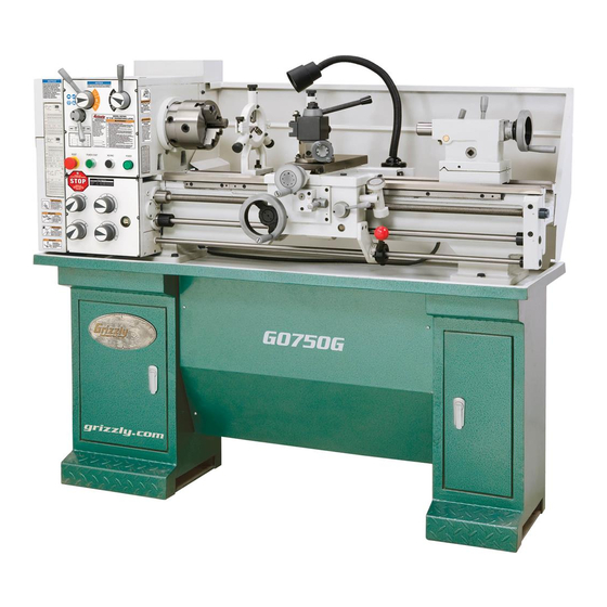
Identification figure 1. Model g0750g identification. A. headstock K. Longitudinal Leadscrew b. d1-5 Camlock Mt#5 spindle Feed rod c. 3-Jaw Chuck 6" M. Control rod D. steady rest N. storage Cabinet E. halogen Work Lamp O. stand Mounting points p. Carriage (see page 5 for details) Follow rest G. -
Page 7: Controls & Components
controls & carriage components refer to figures 2–7 and the following descrip- tions to become familiar with the basic controls of this lathe. Headstock figure 3. Carriage controls. G. Quick-change Tool post: Allows the opera- tor to quickly load and unload tools. H. -
Page 8: Tailstock
Tailstock control panel figure 6. Control panel. figure 4. tailstock controls. y. Emergency Stop/RESET button: stops all machine functions. twist clockwise to reset. power Start: Enables the spindle motor when the emergency stop button is reset. AA. Jog/Inching button: starts forward spindle rotation as long as it is pressed. -
Page 9: Machine Data Sheet
Machine Data Sheet MACHINE DATA SHEET Customer Service #: (570) 546-9663 · To Order Call: (800) 523-4777 · Fax #: (800) 438-5901 MODEL G0750G 12" X 36" GUNSMITHING LATHE Product Dimensions: Weight................................1059 lbs. Width (side-to-side) x Depth (front-to-back) x Height..............67 x 29-1/2 x 56 in. Footprint (Length x Width)........................ - Page 10 Main Specifications: Operation Info Swing Over Bed............................12 in. Distance Between Centers........................36 in. Swing Over Cross Slide..........................7 in. Swing Over Saddle.......................... 11-11/32 in. Swing Over Gap............................17 in. Maximum Tool Bit Size..........................5/8 in. Compound Travel..........................3-1/4 in. Carriage Travel............................
- Page 11 Fluid Capacities Headstock Capacity..........................3.5 qt. Headstock Fluid Type..............ISO 32 (eg. Grizzly T23963, Mobil DTE Light) Gearbox Capacity............................1 qt. Gearbox Fluid Type..............ISO 68 (eg. Grizzly T23962, Mobil Vactra 2) Apron Capacity............................0.5 qt. Apron Fluid Type................ISO 68 (eg. Grizzly T23962, Mobil Vactra 2) Other Specifications: Country Of Origin ...............................
-
Page 12: Section 1: Safety
SEcTION 1: SAfETy for your Own Safety, Read Instruction Manual before Operating This Machine The purpose of safety symbols is to attract your attention to possible hazardous conditions. This manual uses a series of symbols and signal words intended to convey the level of impor- tance of the safety messages. - Page 13 WEARING pROpER AppAREL. do not wear fORcING MAcHINERy. do not force machine. clothing, apparel or jewelry that can become it will do the job safer and better at the rate for entangled in moving parts. Always tie back or which it was designed. cover long hair.
-
Page 14: Additional Safety For Metal Lathes
Additional Safety for Metal Lathes SpEED RATES. operating the lathe at the wrong cHUcKS. Chucks are very heavy and difficult to speed can cause nearby parts to break or the grasp, which can lead to crushed fingers or hands workpiece to come loose, which will result in dan- if mishandled. -
Page 15: Additional Chuck Safety
Additional chuck Safety ENTANGLEMENT. Entanglement with a rotat- cHUcK cApAcITy. Avoid exceeding the capacity ing chuck can lead to death, amputation, broken of the chuck by clamping an oversized workpiece. bones, or other serious injury. never attempt to if the workpiece is too large to safely clamp with slow or stop the lathe chuck by hand, and always the chuck, use a faceplate or a larger chuck if pos- roll up long sleeves, tie back long hair, and remove... -
Page 16: Section 2: Power Supply
SEcTION 2: pOWER SUppLy Availability circuit Requirements for 220v Before installing the machine, consider the avail- This machine is prewired to operate on a 220V power supply circuit that has a verified ground and ability and proximity of the required power supply circuit. -
Page 17: Grounding Instructions
Grounding Instructions Improper connection of the equipment-grounding wire can result in a risk of electric shock. The This machine MUST be grounded. In the event wire with green insulation (with or without yellow of certain malfunctions or breakdowns, grounding stripes) is the equipment-grounding wire. If repair reduces the risk of electric shock by providing a or replacement of the power cord or plug is nec- path of least resistance for electric current. -
Page 18: Section 3: Setup
SEcTION 3: SETUp preparation SUFFOCATION HAZARD! Keep children and pets away the list below outlines the basic process of pre- from plastic bags or packing paring your machine for operation. specific steps materials shipped with this are covered later in this section. machine. -
Page 19: Inventory
Inventory hex Wrenches 2, 4, 5, 6, 8, 10 mm..1 ea W. Wrenches 9/11, 10/12, 12/14, 17/19 mm 1 ea X. handwheel handles ........2 drill Chuck B16 1.5-13mm ......1 the following is a list of items shipped with your z. -
Page 20: Cleanup
cleanup Gasoline or products with low flash points can The unpainted surfaces of your machine are explode or cause fire if coated with a heavy-duty rust preventative that used to clean machin- prevents corrosion during shipment and storage. ery. Avoid cleaning with This rust preventative works extremely well, but it these products. -
Page 21: Site Considerations
Site considerations Weight Load Physical Environment Refer to the Machine Data Sheet for the weight The physical environment where the machine is of your machine. Make sure that the surface upon operated is important for safe operation and lon- which the machine is placed will bear the weight gevity of machine components. -
Page 22: Assembly
Assembly This machine and its parts are heavy! Serious personal Assembling the Model g0750g consists of build- injury may occur if safe ing the cabinet stand assembly, installing the moving methods are not handwheels, placing and securing the lathe on used during the following the stand with power lifting equipment, then steps. - Page 23 to balance the load for lifting, move the 10. position the chip pan on top of the cabinet tailstock and carriage to the right end of the stand and align the six mounting holes with bedway, then lock them in place. those in the cabinets.
-
Page 24: Anchoring To Floor
Anchoring to floor 16. (recommended) use the holes in the bottom of the cabinets as guides for drilling holes in the floor and mount the stand (refer to the following section Anchoring to floor). shim Anchoring the machine to the floor prevents it between the lathe and chip pan as necessary from tipping or shifting and reduces any vibration to level the ways at all four corner locations... -
Page 25: Leveling
Note: If this lathe was shipped with oil in the res- precision level offered by grizzly. ervoirs, do not change that oil until after the test run and spindle break-in procedures. -
Page 26: Power Connection
power connection To connect the power cord to the lathe: press the emergency stop/rEsEt button on the front of the headstock, then remove the electrical box cover from the back. thread the power cord through the strain Electrocution fire relief shown in figure 23. may occur if machine is ungrounded, incorrectly... -
Page 27: Test Run
Test Run Make sure the wires have enough slack between the strain relief and terminal connec- tions so they are not pulled tight or stretched, then tighten the strain relief to secure the once the assembly is complete, test run your cord. - Page 28 to ensure the carriage components do not push the poWEr stArt button, then move unexpectedly move during the following the spindle lever (figure 25) down to start steps, disengage the half nut lever and feed the spindle. the top of the chuck should turn selection lever (see figure 25).
-
Page 29: Spindle Break-In
Spindle break-In Recommended Adjustments Before subjecting the spindle to operational loads, it is essential to complete the break-in process. the following adjustments have been made at the this helps ensure maximum life of spindle bear- factory. however, because of the many variables ings and other precision components by thor- involved with shipping, we recommend that you oughly lubricating them before placing them under... -
Page 30: Section 4: Operations
Regardless of the content in this sec- workpiece. tion, Grizzly Industrial will not be held liable for accidents caused by lack of training. -28- Model G0750G (Mfg. Since 11/12) -
Page 31: Chuck & Faceplate Mounting
chuck & faceplate Installation & Mounting Removal Devices Because chucks are heavy and often awkward this lathe is equipped with a d1-type spindle to hold, some kind of lifting, support, or protec- nose. this type of spindle uses camlocks that are tive device should be used during installation or adjusted with a chuck key to securely mount a removal. -
Page 32: Chuck Installation
chuck Installation incrementally tighten the camlocks in a criss- cross or star pattern to ensure that the chuck seats evenly against the spindle. to ensure accurate work, it is extremely important When the chuck is fully seated and all the to make sure the spindle nose and chuck mating camlocks are tight, verify that the cam line surfaces/tapers are clean. -
Page 33: Registration Marks
chuck Removal Verify that the chuck fits the spindle properly by checking for any gaps between the mating surfaces. To remove the chuck: —if there is not a gap, proceed to Step 8. disConnECt LAthE FroM poWEr! —if there is a gap, remove the chuck, re- clean the mating surfaces carefully, and use an appropriate lifting, support, or protec- re-install. -
Page 34: Scroll Chuck Clamping
Scroll chuck chuck Jaw Reversal clamping this chuck has 2-piece jaws that consist of a top jaw and a master jaw. the top jaw can this 3-jaw scroll-type chuck has an internal scroll- be removed, rotated 180°, and re-installed in gear that moves all jaws in unison when adjusted the reverse position for additional work-holding with the chuck key. -
Page 35: 4-Jaw Chuck
4-Jaw chuck tighten each jaw in small increments. After you have adjusted the first jaw, continue tightening the remaining jaws in an opposing sequence, as shown by the sequential order refer to the chuck Installation or chuck in the figure below. Removal sections for instructions on installing or removing the 4-jaw chuck. -
Page 36: Faceplate
faceplate To mount a non-concentric workpiece to the faceplate: disConnECt LAthE FroM poWEr! refer to the prior chuck Installation and chuck Removal sections for instructions on installing or protect the bedway with a piece of plywood. removing the faceplate. With help from another person or a holding the faceplate included with your lathe can be device to support the workpiece, position it used for a wide range of operations, including... -
Page 37: Tailstock
Tailstock Using Quill Move the quill lock lever away from the spin- dle to unlock the quill. the tailstock (see figure 38) is typically used to turn the quill handwheel clockwise to move support long workpieces by means of a live or the quill toward the spindle or counterclock- dead center (refer to centers on page 75 in the wise to move it away from it. -
Page 38: Removing Tooling
Removing Tooling however, other tooling without tangs, such as the four remaining tools shown previously, can use a shop rag to hold the tool. still be used if the potential load will not exceed the strength of the tapered fit. For example, this rotate the quill handwheel counterclockwise includes smaller drill chucks, drill bits, and cen- until the tool is forced out of the quill. -
Page 39: Aligning Tailstock To Spindle Centerline
Aligning Tailstock to Spindle To offset the tailstock: centerline rotate the adjustment set screws (shown in this is an essential adjustment that should be ver- figure 42) in the opposite directions for the ified or performed each time the tailstock is used desired offset. - Page 40 Note: As long as this dead center remains in use calipers to measure both ends of the the chuck, the point of the center will remain workpiece. true to the spindle centerline. The point will have to be refinished whenever the center is —...
-
Page 41: Centers
centers Live centers A live center has bearings that allow the center tip and the workpiece to rotate together; it can be installed in the tailstock quill for higher speeds. figure 47 shows the Mt#3 dead centers and live center included with the lathe. in addition, an Mounting Dead center in Spindle Mt#5–Mt#3 tapered spindle sleeve is included for mounting in the spindle. -
Page 42: Removing Center From Spindle
Removing center from Spindle use the quill handwheel to feed the quill out from the casting approximately 1". to remove the sleeve and center from the spindle, insert a piece of round bar stock (or similar) Note: The maximum quill travel is 3 ⁄... -
Page 43: Mounting Workpiece Between Centers
Drill chuck & Arbor Mounting Workpiece between centers disConnECt LAthE FroM poWEr! the drill chuck attaches to the tailstock quill with drill center holes in both ends of the the included B16 to Mt#3 arbor, shown in figure workpiece. 52. Matched tapers on the arbor and the inside of the chuck create a semi-permanent assembly install a dead center in the spindle with a when properly joined. -
Page 44: Steady Rest
Steady Rest Loosen the clamp knob that secures the two halves of the steady rest and open the top portion, as shown in figure 54. the steady rest supports long, small diameter shafts and can be mounted anywhere along the length of the bedway. -
Page 45: Follow Rest
follow Rest carriage & Slide Locks the follow rest mounts to the saddle with two cap screws (see figure 55). it is used on long, the carriage, cross slide, and compound rest slender parts to prevent workpiece deflection from have locks that can be tightened to provide addi- the pressure of the cutting tool during operation. -
Page 46: Compound Rest
compound Rest Tool post the quick-change tool post (see figure 58) is a the compound rest handwheel has an indirect- read graduated scale. this means that the dis- 200-series design. tance shown on the scale represents the actual distance the cutting tool moves. the base of the Top Nut compound rest has another graduated scale used Lock Lever... -
Page 47: Aligning Cutting Tool With Spindle Centerline
secure the tool with at least two set screws. Tools Needed hex Wrench 5mm ..........1 Adjust the cutting tool height to the spindle open-End Wrench/socket 27mm ...... 1 centerline, as instructed in the next subsec- steel shims ........As needed tion. -
Page 48: Spider
Spider Manual feed the handwheels shown in figure 62 allow the this lathe is equipped with a set of outboard operator to manually move the cutting tool. spindle supports otherwise known as a "spider" (see figure 61). Compound Carriage rest spider screw handwheel handwheel... -
Page 49: Spindle Speed
Spindle Speed Setting Spindle Speed the alpha and numeric spindle speed levers, shown in figure 64, are used to select one of the nine spindle speeds. using the correct spindle speed is important for getting safe and satisfactory results, as well as maximizing tool life. -
Page 50: Configuration Example
power feed configuration Example figure 66 shows the levers positioned for a spindle speed of 600 rpM. Both the carriage and cross slide have power feed Note: If the spindle speed levers do not easily capability when the carriage is engaged with the adjust into position, rotate the spindle by hand feed rod. -
Page 51: Power Feed Controls
b. feed Rate chart: displays the settings for the quick-change gearbox dials for the selected feed rate. refer to Setting power To avoid damaging the lathe, ALWAyS make feed Rate subsection on the next page for sure the spindle is completely stopped detailed instructions. -
Page 52: Setting Power Feed Rate
Setting power feed Rate Locate the applicable change gear on the chart—in this case it is the 60t gear. the feed rate chart (see figure 67 on previous page for location) displays the settings for the install the 60t gear in the upper "a" position headstock feed controls for feed rates. -
Page 53: End Gears
End Gears Inch Threading configuration A change gear corresponding to the "b" row on the chart is installed in the lower "b" position so it meshes with the 120t gear. A change gear cor- the end gears must be correctly setup for power responding to the "a"... -
Page 54: End-Gear Configuration Example
End-Gear configuration Example While holding the 120T/127T gears, loosen the arm support hex nut and slowly let the Follow the example below to better understand gears pivot down and away from the upper how to configure the end gears for inch threading. "a"... -
Page 55: Threading
Threading 10. slide the 120T gear against the lower 54T gear (see figure 79) until they mesh with 0.002" to 0.004" backlash, then tighten the gear support hex nut. the following subsections will describe how to use the threading controls and charts to set up the lathe for a threading operation. -
Page 56: Apron Threading Controls
Apron Threading controls Locate A and c to the left of 18 tpi and find 1 and v above it. the half nut lever engages the carriage with the leadscrew, which moves the carriage and cutting Note: In the next step, use the chuck key to tool along the length of the workpiece for thread- rock the spindle back-and-forth to help mesh ing operations (see figure 82). -
Page 57: Thread Dial
Thread Dial Thread Dial chart Tools Needed the thread dial chart is located on the headstock, as shown in figure 84. hex Wrench 5mm ..........1 the numbers on the thread dial are used with the thread dial chart to show when to engage the half nut during inch threading. - Page 58 The following examples explain how to use Odd Numbered TpI: For odd numbered tpi, the thread dial and the thread dial chart. use only the number 1 on the thread dial (see the example in figure 88). TpI Divisible by 8: For threading a tpi divisible by eight, use any line on the thread dial (see the Table Thread Dial...
-
Page 59: Section 5: Accessories
To reduce this risk, only install accessories sharp. recommended for this machine by Grizzly. NOTICE Refer to our website or latest catalog for additional recommended accessories. T23962—ISO 68 Moly-D Machine Oil, 5 gal. - Page 60 H2987—½" bent Lathe Dog H8314—Threading Tool Holder, Left-Hand H2988—1" bent Lathe Dog H8315—Threading Tool Holder, Right-Hand H2989—1½" bent Lathe Dog For threading tough to machine materials. Made H2990—2" bent Lathe Dog of high quality alloy steel, these holders offer H2991—3" bent Lathe Dog maximum rigidity because of the “on edge”...
- Page 61 G4985—Machine Shop practice-vol. 1 - book SbcE3450—How to Run a Lathe—English G4986—Machine Shop practice-vol. 2 - book First printed in 1907, this 56th edition is an exact Karl hans Moltrecht's two-volume work on metal- reprint from 1966. Well illustrated with vintage working operations delivers the ultimate teaching photos and drawings, this 128-page book is writ- and reference tool for basic cutting operations,...
- Page 62 T10109—Gunsmith D-1 back plate T10118—Tailstock Digital Readout these d1-5 Back plates have spiders machined here’s the slickest setup for managing the exact into them, which allows shorter barrels to be sup- depth of cut with your tailstock! Both the scale ported through the headstocks of larger lathes.
-
Page 63: Section 6: Maintenance
SEcTION 6: MAINTENANcE Daily, After Operations • press the emergency stop/rEsEt button Always disconnect power (to prevent accidental startup). to the machine before • Vacuum/clean all chips and swarf from bed, performing maintenance. slides. failure to do this may • Wipe down all unpainted or machined sur- result in serious person- faces with an oiled rag. -
Page 64: Lubrication
Quick-Change gearbox daily Apron daily Headstock Bedways daily oil type ..grizzly t23963 or iso 32 Equivalent Longitudinal Leadscrew daily oil Amount .......... 3.5 Quarts Ball oilers daily Check/Add Frequency ......... daily Change Frequency ....... semi-Annually... -
Page 65: Quick-Change Gearbox
Quick-change Gearbox Adding Oil the oil fill plug is located on top of the headstock, oil type ..grizzly t23962 or iso 68 Equivalent as shown in figure 107. oil Amount ..........1 Quart Check/Add Frequency ......... daily Change Frequency ........ Annually... -
Page 66: Apron
Apron bedways oil type ..grizzly t23962 or iso 68 Equivalent oil type ..grizzly t23962 or iso 68 Equivalent oil Amount .......... 0.5 Quarts oil Amount ......... As needed Check/Add Frequency ......... daily Lubrication Frequency ......... daily Change Frequency ........ Annually Before lubricating the bedways (see figure 112), clean them with mineral spirits. -
Page 67: Ball Oilers
Oilers oil type ..grizzly t23963 or iso 32 Equivalent oil Amount ........1 or 2 squirts Lubrication Frequency ......... daily this lathe has 15 ball oilers that should be oiled on a daily basis before beginning operation. refer to figures 113–116 for their locations. -
Page 68: End Gears
End Gears Lubricating disConnECt LAthE FroM poWEr! grease type ..........nLgi#2 Frequency ....Annually or When Changing remove the end gear cover and all the end gears shown in figure 118. the end gears, shown in figure 118, should always have a thin coat of heavy grease to Clean the end gears thoroughly with mineral minimize corrosion, noise, and wear. -
Page 69: Machine Storage
Machine Storage bringing Lathe Out of Storage re-install the V-belts and re-tension them (refer to page 75) if you removed them for storage purposes. to prevent the development of rust and corrosion, the lathe must be properly prepared if it will be remove the moisture absorbing desiccant stored for a long period of time. -
Page 70: Section 7: Service
SEcTION 7: SERvIcE Review the troubleshooting and procedures in this section if a problem develops with your machine. If you need replacement parts or additional help with a procedure, call our Technical Support at (570) 546-9663. Note: Please gather the serial number and manufacture date of your machine before calling. Troubleshooting Motor &... -
Page 71: Lathe Operation
Lathe Operation symptom possible Cause possible solution Entire machine 1. Workpiece is unbalanced. 1. re-install workpiece as centered with the spindle vibrates upon bore as possible. startup and while 2. Loose or damaged V-belt(s). 2. re-tension/replace the V-belt(s) as necessary (see running. - Page 72 symptom possible Cause possible solution Workpiece is 1. headstock and tailstock are not properly 1. re-align the tailstock to the headstock spindle centerline (see page 37). tapered. aligned with each other. Chuck jaws will 1. Chips lodged in the jaws or scroll plate. 1.
-
Page 73: Backlash Adjustment
backlash Adjustment Leadscrew nut Backlash is the amount of play in a leadscrew and can be felt as the free play in a handwheel Backlash when changing direction of rotation. the amount Adjustment of the backlash can be viewed on the handwheel Cap screw micrometer-collar graduated dial. -
Page 74: Leadscrew End Play Adjustment
Leadscrew End play Gib Adjustment Adjustment the goal of adjusting the gib screws is to remove sloppiness or "play" from the ways without over- After a long period of time, you may find that the adjusting them to the point where they become leadscrew develops a bit of end play. -
Page 75: Cross Slide Gib
compound Slide Gib Tools Needed standard screwdriver #2 ........1 figure 124 shows the gib location on the com- hex Wrench 3mm ..........1 pound slide. the compound slide gib adjusts in the same manner and with the same tools as the cross Slide Gib cross slide gib. -
Page 76: Half Nut Adjustment
Half Nut Adjustment the saddle gib is located on the bottom of the back edge of the slide (figure 126). this gib is designed differently than the cross or compound slide gibs. instead of being a wedge-shaped plate, the half-nut mechanism can be adjusted if it it is a flat bar. -
Page 77: V-Belt Tension & Replacement
v-belt Tension & Check the belt tension: Each belt is correctly tensioned when there is approximately ⁄ " Replacement deflection when it is pushed with moderate pressure, as shown in figure 129. After initial break in, the V-belts slightly stretch and seat into the pulley. -
Page 78: Leadscrew Shear Pin Replacement
"n" case of a carriage crash or the lathe is overloaded. Contact grizzly Customer service at (570) 546- 9663 to order a replacement shear pin (part p0750g0960). figure 131. gearbox dial set to "n" . -
Page 79: Feed Clutch Adjustment
feed clutch Tools Needed hex Wrench 4mm ..........1 Adjustment To adjust the feed rod clutch: disConnECt LAthE FroM poWEr! this lathe is equipped with a feed rod clutch, shown in figure 132, that connects the feed drive point the top right dial at "n", then position hub with the feed rod through a set of spring- the bottom right hand gearbox dial pointer loaded ball bearings. -
Page 80: Gap Insert Removal & Installation
Gap Insert Removal Loosen the preload set screw (see figure 134) a few turns until it no longer contacts the & Installation headstock. tap the outside of the gap piece with a dead blow hammer to loosen it, and, with the help this lathe is equipped with a removable gap of another person, remove the gap piece. -
Page 81: Bearing Preload
bearing preload remove the chuck, then shift the spindle to neutral by positioning the alpha spindle speed lever between "C" and "B" and the numeric spindle speed lever between the "I" this lathe is shipped from the factory with the and "II", as shown in figure 136. - Page 82 Loosen the inner spanner nut one turn. 11. insert the chuck key into a cam socket to prevent the spindle from turning, then tighten Note: You may have to tap on the outboard the inner spanner nut until the dial indicator end of the spindle as explained in Step 8, to needle just stops moving (see figure 141).
- Page 83 12. tighten the spanner nut an additional ⁄ " To confirm that the bearings are correctly pre- along its circumference. see figure 142 for loaded: the example of this measurement. re-attach all removed lathe components and prepare it for operation. ⁄...
-
Page 84: Section 8: Wiring
Technical source. Support at (570) 546-9663. The photos and diagrams included in this section are best viewed in color. You can view these pages in color at www.grizzly.com. -82- Model G0750G (Mfg. Since 11/12) -
Page 85: Wiring Overview
Wiring Overview Electrical cabinet page 84 power Supply Spindle connection Switch page 88 page 87 control panel page 87 Work Lamp page 88 Spindle Motor page 88 component Location Index Work Lamp Electrical page 88 Cabinet page 84 Control panel page 87 spindle Motor page 86... -
Page 86: Electrical Cabinet Wiring
Electrical cabinet Wiring Relay 20-21 = 110V JRS4-09-25d 20-22 = 220V Transformer 20-23 = 230V 20-24 = 240V WUXI No. 5. Machine Tool 20-25 = 380V STOP RESET JBK5-100VATH 20-26 = 400V 1 L1 3 L2 5 L3 21NC 1 L1 3 L2 5 L3 21NC... -
Page 87: Electrical Cabinet
Electrical cabinet figure 144. Electrical cabinet wiring. READ ELECTRICAL SAFETY -85- Model G0750G (Mfg. Since 11/12) ON PAGE 82! -
Page 88: Motor Wiring
Motor Wiring figure 145. spindle motor junction box. Ground Capacitor 20MFD 450VAC to Electrical Cabinet page 84 Start Capacitor 150MFD 250VAC Motor run Capacitor start Capacitor figure 146. start capacitor. figure 147. run capacitor. READ ELECTRICAL SAFETY -86- Model G0750G (Mfg. Since 11/12) ON PAGE 82! -
Page 89: Control Panel Wiring
control panel Wiring power Light E-stop power start/on Button Jog Button Button w/Light figure 148. Control panel wiring. CONTROL PANEL E-STOP POWER START/ON POWER BUTTON BUTTON W/LIGHT BUTTON LIGHT HUILONG LA103 HUILONG LA103 110V LA103 10A 660V 10A 660V HUILONG XD103 110V HUILONG... -
Page 90: Additional Component Wiring
Additional component Wiring Work Lamp Junction Block figure 149. Work lamp wiring. to Electrical Cabinet page 84 Spindle Rotation Switch to Electrical Cabinet page 84 figure 150. spindle on/oFF rotation switch. power connection Wiring Ground to Electrical Cabinet page 84 6-15 Plug (As Recommended) READ ELECTRICAL SAFETY... -
Page 91: Section 9: Parts
Note: We do our best to stock replacement parts whenever possible, but we cannot guarantee that all parts shown here are available for purchase. Call (800) 523-4777 or visit our online parts store at www.grizzly.com to check for availability. -
Page 92: Headstock Internal Gears
Headstock Internal Gears -90- Model G0750G (Mfg. Since 11/12) - Page 93 Headstock Internal Gears parts List REF PART # DESCRIPTION REF PART # DESCRIPTION PR56M EXT RETAINING RING 45MM PK183M KEY 8 X 8 X 80 P4003G0102 GEAR 36T PK43M KEY 8 X 8 X 45 P4003G0103 GEAR 55T P0750G0141 BUTTON HD CAP SCR M3-.5 X 8 PK14M KEY 5 X 5 X 18 P4003G0142 SPINDLE D1-5...
-
Page 94: Headstock Controls
Headstock controls -92- Model G0750G (Mfg. Since 11/12) - Page 95 Headstock controls parts List PART # DESCRIPTION REF PART # DESCRIPTION P4003G0175 HEADSTOCK OIL FILL PLUG M16-2.0 P4003G1102 FRONT CONTROL PLATE P4003G0176 HEADSTOCK COVER PSS04M SET SCREW M6-1 X 12 PCAP06M CAP SCREW M6-1 X 25 P0750G0230 HANDWHEEL HANDLE M8-1.25 X 40 P4003G0178 HEADSTOCK COVER GASKET P4003G1106 HANDLE HUB PRP05M...
-
Page 96: Quick-Change Gearbox
Quick-change Gearbox -94- Model G0750G (Mfg. Since 11/12) - Page 97 Quick-change Gearbox parts List REF PART # DESCRIPTION REF PART # DESCRIPTION P6203-2RS BALL BEARING 6203-2RS 345 P0750G0345 SHIFT FORK A RACK P0750G0302 SPACER 346 P0750G0346 SHIFT FORK B PR06M EXT RETAINING RING 16MM 347 P0750G0347 SHIFT FORK B RACK P0750G0304 COMBO GEAR 16T/24T 348 P0750G0348 O-RING 12 X 1.9 P6202-2RS...
-
Page 98: End Gears
End Gears PART # DESCRIPTION PART # DESCRIPTION PN02M HEX NUT M10-1.5 PCAP28M CAP SCREW M6-1 X 15 PWF10M FENDER WASHER 10MM PWF06M FENDER WASHER 6MM P6203ZZ BALL BEARING 6203ZZ PCAP13M CAP SCREW M8-1.25 X 30 PR23M INT RETAINING RING 40MM P0750G0417 STUD-FT M10-1.5 X 70 PR78M EXT RETAINING RING 55MM... -
Page 99: Apron
Apron -97- Model G0750G (Mfg. Since 11/12) -
Page 100: Apron Parts List
Apron parts List PART # DESCRIPTION PART # DESCRIPTION P07090501 GEAR 60T P07090550 OIL SIGHT GLASS M20-1.5 PRP05M ROLL PIN 5 X 30 PRP91M ROLL PIN 5 X 35 P0750G0503 GEAR 40T P07090552 COMPRESSION SPRING P0750G0504 PINION 13T PSTB004 STEEL BALL 3/16 PSS121M SET SCREW M6-1 X 16 PILOT POINT P07090554... - Page 101 Saddle 638 639 -99- Model G0750G (Mfg. Since 11/12)
-
Page 102: Saddle Parts List
Saddle parts List PART # DESCRIPTION PART # DESCRIPTION PSS20M SET SCREW M8-1.25 X 8 P0750G0626 OIL FILL PLUG M10-1.5 PLUBE004M BALL OILER 7MM TAP-IN P0750G0627 LEFT GIB SLIDE P0750G0603 CROSS SLIDE P0750G0628 GEAR 17T P0750G0604 GIB SCREW P0750G0629 CROSS SLIDE LEADSCREW PSS03M SET SCREW M6-1 X 8 PRP111M... -
Page 103: Compound Rest & Tool Post
compound Rest & Tool post -101- Model G0750G (Mfg. Since 11/12) - Page 104 compound Rest & Tool post parts List PART # DESCRIPTION PART # DESCRIPTION P0750G0701 TOOL POST HANDLE M12-1.75 X 8 P0750G0720 GIB SCREW P0750G0702 TOOL POST HANDLE HUB P0750G0721 COMPOUND LEADSCREW NUT P0750G0703 TOOL POST BUSHING PN01M HEX NUT M6-1 P0750G0704 QUICK CHANGE TOOL POST BLOCK PSS11M SET SCREW M6-1 X 16...
-
Page 105: Tailstock Parts List
Tailstock parts List 814 833 PART # DESCRIPTION PART # DESCRIPTION P4003G0701 TAILSTOCK ASSEMBLY P4003G0717 LOCK SCREW M8-1.25 X 25 PK136M KEY 8 X 8 X 30 P4003G0718 LOCK SHAFT P4003G0703 TAILSTOCK QUILL P4003G0719 HANDLE M12-1.75 P4003G0704 TAILSTOCK BODY P4003G0720 SWING BOLT M12-1.75 P4003G0705 CLAMPING BASE PRP05M ROLL PIN 5 X 30... -
Page 106: Lathe Bed & Motor
Lathe bed & Motor -104- Model G0750G (Mfg. Since 11/12) - Page 107 Lathe bed & Motor parts List PART # DESCRIPTION REF PART # DESCRIPTION P4003G801 COGGED V-BELT V13X795 P07091134 END PLUG PSS05M SET SCREW M5-.8 X 10 PLUBE001M BALL OILER 6MM TAP-IN PK107M KEY 8 X 8 X 20 PCAP35M CAP SCREW M8-1.25 X 60 PW04M FLAT WASHER 10MM P07091137...
-
Page 108: Steady & Follow Rest Assemblies
Steady & follow Rest Assemblies 1000 1001 1100 1002 1020 1019 1101 1018 1003 1102 1120 1004 1017 1103 1016 1005 1121 1006 1118 1015 1119 1105 1007 1008 1123 1006 1013 1106 1108 1009 1122 1012 1010 1011 PART # DESCRIPTION PART # DESCRIPTION... -
Page 109: Electrical Components
Electrical components 1203 1202 1204 1202-1 1203-1 1201 1205 1206 1217 1207 1218 1208 1209 1216 1216-3 1210 1211 1212 1213 1214 1215 1216-1 1216-2 1219 -107- Model G0750G (Mfg. Since 11/12) -
Page 110: Rear & Side Machine Labels
FOR GRIZZLY MACHINES ONLY! All labels created by Grizzly Industrial, Inc. are motion. Disconnect copyrighted and must only be used on Grizzly brand machines. Never use Grizzly’s label understood, request CAUTION artwork on other brands of machines. -
Page 111: Front Machine Labels
FOR GRIZZLY MACHINES ONLY! All labels created by Grizzly Industrial, Inc. are machine. If safe operation supervised personnel are SERVICE. copyrighted and must only be used on Grizzly brand machines. Never use Grizzly’s label procedures are not clearly allowed to operate this artwork on other brands of machines. -
Page 112: Section 10: Appendix
SEcTION 10: AppENDIX Threading & feed charts -110- Model G0750G (Mfg. Since 11/12) -
Page 113: Warranty Card
Would you recommend Grizzly Industrial to a friend? _____ Yes _____No Would you allow us to use your name as a reference for Grizzly customers in your area? Note: We never use names more than 3 times. _____ Yes _____No 10. - Page 114 FOLD ALONG DOTTED LINE Place Stamp Here GRIZZLY INDUSTRIAL, INC. P.O. BOX 2069 BELLINGHAM, WA 98227-2069 FOLD ALONG DOTTED LINE Send a Grizzly Catalog to a friend: Name_______________________________ Street_______________________________ City______________State______Zip______ TAPE ALONG EDGES--PLEASE DO NOT STAPLE...
-
Page 115: Warranty & Returns
WARRANTy & RETURNS Grizzly Industrial, Inc. warrants every product it sells for a period of 1 year to the original purchaser from the date of purchase. This warranty does not apply to defects due directly or indirectly to misuse, abuse, negligence, accidents, repairs or alterations or lack of maintenance.