Table of Contents
Advertisement
Quick Links
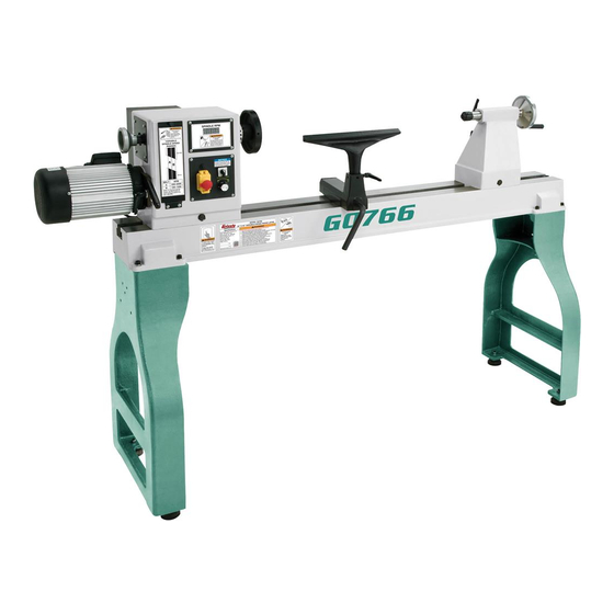
MODEL G0766
22" X 42" VARIABLE-SPEED
WOOD LATHE
OWNER'S MANUAL
(For models manufactured since 11/17)
COPYRIGHT © MARCH, 2015 BY GRIZZLY INDUSTRIAL, INC., REVISED DECEMBER, 2017 (HE)
WARNING: NO PORTION OF THIS MANUAL MAY BE REPRODUCED IN ANY SHAPE
OR FORM WITHOUT THE WRITTEN APPROVAL OF GRIZZLY INDUSTRIAL, INC.
#MN17299 PRINTED IN CHINA
V3.12.17
Advertisement
Table of Contents

Related Manuals for Grizzly G0766


Summary of Contents for Grizzly G0766
- Page 1 OWNER'S MANUAL (For models manufactured since 11/17) COPYRIGHT © MARCH, 2015 BY GRIZZLY INDUSTRIAL, INC., REVISED DECEMBER, 2017 (HE) WARNING: NO PORTION OF THIS MANUAL MAY BE REPRODUCED IN ANY SHAPE OR FORM WITHOUT THE WRITTEN APPROVAL OF GRIZZLY INDUSTRIAL, INC.
- Page 2 This manual provides critical safety instructions on the proper setup, operation, maintenance, and service of this machine/tool. Save this document, refer to it often, and use it to instruct other operators. Failure to read, understand and follow the instructions in this manual may result in fire or serious personal injury—including amputation, electrocution, or death.
-
Page 3: Table Of Contents
Table of Contents INTRODUCTION ..........2 SECTION 5: ACCESSORIES ......34 Contact Info............ 2 SECTION 6: MAINTENANCE ......37 Manual Accuracy ........... 2 Schedule ............37 Identification ........... 3 Cleaning & Protecting ........37 Controls & Components ......... 4 Lubrication ........... 37 Glossary Of Terms ......... -
Page 4: Introduction
ID label (see below). This information is required for us to provide proper tech support, and it helps us determine if updated documenta- tion is available for your machine. Manufacture Date Serial Number Model G0766 (Mfd. Since 11/17) -
Page 5: Identification
Tool Rest Lock Handle Lock Handle Tool Rest Belt Tension Speed Base Lever Control Knob Lock Lever ON/OFF Switch Spindle Indexing Holes To reduce your risk of serious injury, read this entire manual BEFORE using machine. Model G0766 (Mfd. Since 11/17) -
Page 6: Controls & Components
E. Belt Tension Lock Handle: Locks belt ten- sion lever in place. M. Tool Rest Base Lock Lever: Secures tool rest base in position. Belt Tension Lever: Increases and decreas- es amount of tension on belt. Model G0766 (Mfd. Since 11/17) -
Page 7: Glossary Of Terms
The following is a list of common definitions, terms and phrases used throughout this manual as they relate to this wood lathe and turning in general. Become familiar with these terms for assembling, adjusting or operating this machine. Your safety is VERY important to us at Grizzly! Bed: The long, rail-like metal base to which... -
Page 8: Machine Data
MACHINE DATA SHEET Customer Service #: (570) 546-9663 · To Order Call: (800) 523-4777 · Fax #: (800) 438-5901 MODEL G0766 22" X 42" VARIABLE‐SPEED WOOD LATHE Product Dimensions: Weight................................496 lbs. Width (side-to-side) x Depth (front-to-back) x Height..............81 x 23 x 49-1/2 in. - Page 9 The information contained herein is deemed accurate as of 12/13/2017 and represents our most recent product specifications. Model G0766 PAGE 2 OF 2 Due to our ongoing improvement efforts, this information may not accurately describe items previously purchased. Model G0766 (Mfd. Since 11/17)
-
Page 10: Section 1: Safety
Everyday ery. Never operate under the influence of drugs or eyeglasses are NOT approved safety glasses. alcohol, when tired, or when distracted. Model G0766 (Mfd. Since 11/17) - Page 11 EXPERIENCING DIFFICULTIES. If at any time debris. Make sure they are properly installed, you experience difficulties performing the intend- undamaged, and working correctly BEFORE ed operation, stop using the machine! Contact our operating machine. Technical Support at (570) 546-9663. Model G0766 (Mfd. Since 11/17)
-
Page 12: Additional Safety For Wood Lathes
SANDING/POLISHING. To reduce entanglement CHECK CLEARANCES. Before starting spindle, risk, remove tool rest before sanding. Never verify workpiece has adequate clearance by completely wrap sandpaper around workpiece. hand-rotating it through its entire range of motion. -10- Model G0766 (Mfd. Since 11/17) -
Page 13: Section 2: Power Supply
To reduce the risk of these hazards, avoid over- loading the machine during operation and make sure it is connected to a power supply circuit that meets the specified circuit requirements. -11- Model G0766 (Mfd. Since 11/17) -
Page 14: Grounding Requirements
Minimum Gauge Size ......12 AWG all local codes and ordinances. Maximum Length (Shorter is Better)..50 ft. -12- Model G0766 (Mfd. Since 11/17) -
Page 15: Section 3: Setup
(or other you are completely satisfied with the machine and lifting equipment) rated for have resolved any issues between Grizzly or the weight of this machine. shipping agent. You MUST have the original pack- aging to file a freight claim. It is also extremely helpful if you need to return your machine later. -
Page 16: Inventory
Figure 6. Stand legs. A. Lathe Assembly —Headstock (mounted) ......1 —Tool Rest Base (mounted) ...... 1 —Tailstock (mounted) ......... 1 —Faceplate 6" (installed) ......1 Figure 7. Loose inventory components. Figure 5. Lathe assembly. -14- Model G0766 (Mfd. Since 11/17) -
Page 17: Cleanup
Figure 8. T23692 Orange Power Degreaser. off the rest with the rag. Repeat Steps 2–3 as necessary until clean, then coat all unpainted surfaces with a quality metal protectant to prevent rust. -15- Model G0766 (Mfd. Since 11/17) -
Page 18: Site Considerations
Only install in an Shadows, glare, or strobe effects that may distract access restricted location. or impede the operator must be eliminated. 21" 23" 81" Figure 9. Minimum working clearances. -16- Model G0766 (Mfd. Since 11/17) -
Page 19: Anchoring To Floor
MUST follow the anchoring methodology specified by the code. Lag Screw Flat Washer Machine Base Figure 12. Securing lathe assembly. Lag Shield Anchor Concrete Drilled Hole Figure 10. Popular method for anchoring machinery to a concrete floor. -17- Model G0766 (Mfd. Since 11/17) - Page 20 Figure 15. Tool rest installed on the tool rest thread top hex nut back on. Do not tighten base. hex nuts yet. Remove supporting block and repeat Steps 5–6 on other leg. Figure 14. Machine feet installed. -18- Model G0766 (Mfd. Since 11/17)
-
Page 21: Test Run
Set spindle direction switch to neutral or "O" position and turn speed control knob all the way counterclockwise. Squeeze tab on bottom of Emergency Stop button, lift button to open switch cover, and press green ON button to start machine. -19- Model G0766 (Mfd. Since 11/17) -
Page 22: Section 4: Operations
Read books/magazines or get formal training before beginning any proj- ects. Regardless of the content in this sec- tion, Grizzly Industrial will not be held liable for accidents caused by lack of training. -20- Model G0766 (Mfd. Since 11/17) -
Page 23: Workpiece Inspection
Workpiece Inspection Adjusting Headstock Some workpieces are not safe to turn or may The Model G0766 headstock is equipped with a require modification before they are safe to turn. cam-action clamping system to secure it to the Before turning, inspect all workpieces for the lathe bed. -
Page 24: Adjusting Tailstock
BEFORE cutting, and cutting tool injury may occur by tailstock moving during is properly positioned to cut at the correct operation and workpiece being ejected at angle for tool and operation type. high speed. -22- Model G0766 (Mfd. Since 11/17) - Page 25 Loosen tool rest lock handle (see Figure 18). Position tool rest in desired location. Tool Rest Base Re-tighten tool rest lock handle to secure tool Lock Lever rest in position. Figure 18. Tool rest controls. -23- Model G0766 (Mfd. Since 11/17)
-
Page 26: Installing/Removing Headstock Center
Insert tapered end of center into spindle, and push it in with a quick, firm motion, as shown in Figure 19. Figure 20. Removing the headstock center. Figure 19. Installing center in headstock spindle. -24- Model G0766 (Mfd. Since 11/17) -
Page 27: Installing/Removing Tailstock Center
Otherwise, attempting to pull it out by hand—a properly workpiece can be thrown from lathe caus- installed center will not pull out easily. ing serious personal injury or death. -25- Model G0766 (Mfd. Since 11/17) -
Page 28: Installing Faceplate
Installing Faceplate Changing Speed Ranges To install faceplate: The Model G0766 pulley belt configurations pro- DISCONNECT MACHINE FROM POWER! vide two speed ranges (see Figure 24). Insert indexing pin into an indexing hole and rotate spindle until pin engages to prevent... - Page 29 Use belt tension lever (see Figure 27) to lift motor assembly all the way up, then re- tighten belt tension lock handle—this will hold motor in place while you change belt position. -27- Model G0766 (Mfd. Since 11/17)
-
Page 30: Indexing
By inserting the indexing pin into one of the four outer indexes of the Model G0766 spindle housing and engaging one of the 12 inner indexes in the spindle, the workpiece can be positioned in 10°... - Page 31 Otherwise, spin- ning workpiece could force lathe tool out Figure 35. Spur center properly embedded. of your hands or entangle your hands with workpiece. Failure to heed this warning could result in serious personal injury. -29- Model G0766 (Mfd. Since 11/17)
-
Page 32: Faceplate Turning
"round" as possible, as described in Spindle Turning, Step 5 (see Page 29). Center faceplate on workpiece and attach it (see Figure 37) with wood screws. Figure 37. Typical attachment of faceplate to workpiece. -30- Model G0766 (Mfd. Since 11/17) -
Page 33: Outboard Turning
This will position the spindle so it is not directly over the bed whereby outboard turning can safely be accomplished. -31- Model G0766 (Mfd. Since 11/17) -
Page 34: Sanding/Finishing
Failure to do so could cause tool to be cause serious injury. pulled out of operator's control and ejected Never wrap sandpa- at high speed. per or finishing materi- Workpiece als completely around workpiece. -32- Model G0766 (Mfd. Since 11/17) -
Page 35: Selecting Turning Tools
The Swan Neck Hollowing Tool shown on Page 34 is a good example of a speciality tool. Figure 42. Example of a skew chisel. -33- Model G0766 (Mfd. Since 11/17) -
Page 36: Section 5: Accessories
" parting tool. Also serious personal injury or machine damage. includes a fitted aluminum case. To reduce this risk, only install accessories recommended for this machine by Grizzly. NOTICE Refer to our website or latest catalog for additional recommended accessories. - Page 37 Knurled knob locks dividers from 0–90°. Size indicates leg lengths. Figure 49. Model T10117 Big Mouth Dust Hood. Figure 51. Models H5884–H5887 Pencil Dividers. www.grizzly.com 1-800-523-4777 order online at or call -35- Model G0766 (Mfd. Since 11/17)
-
Page 38: Recommended Metal Protectants
This "trailer" shows all of the projects you'll learn to build and the skills you'll learn to master in this essential DVD. Figure 53. Model G1069 Live Center. Figure 55. Model T21884 Turning Basics for Furniture Makers. -36- Model G0766 (Mfd. Since 11/17) -
Page 39: Section 6: Maintenance
• Loose machine components. • Any other unsafe condition. Daily: All bearings for the Model G0766 are lubricated • Clean off dust buildup. and sealed at the factory, and do not need addi- • Clean and lubricate lathe bed, spindle, and tional lubrication. -
Page 40: Section 7: Service
7. Motor bearings at fault. 7. Test by rotating shaft; rotational grinding/loose shaft requires bearing replacement. 8. Belt slapping cover. 8. Replace/realign belt. 9. Workpiece/faceplate at fault. 9. Center workpiece in chuck/faceplate; reduce RPM. -38- Model G0766 (Mfd. Since 11/17) -
Page 41: Wood Lathe Operation
Quill will not move 1. Keyway is not aligned with quill lock lever. 1. Align quill keyway and quill lock lever and slightly forward when tighten lever to engage keyway. handwheel is turned -39- Model G0766 (Mfd. Since 11/17) -
Page 42: Changing Belt
Loosen belt tension lock handle (see grooves, then secure front belt access cover. Figure 57). Belt Tension Lever Belt Tension Lock Handle Figure 57. Location of belt tension lever and belt tension lock handle. -40- Model G0766 (Mfd. Since 11/17) -
Page 43: Section 8: Wiring
Technical Support at (570) 546-9663. The photos and diagrams included in this section are best viewed in color. You can view these pages in color at www.grizzly.com. -41- Model G0766 (Mfd. Since 11/17) -
Page 44: Wiring Diagram
General Industrial 220V 15A Speed Control Potentiometer WX110(010) 10K±5% ON/OFF Switch w/Emergency Stop KEDU KJD17B 250V 18A MOTOR Headstock Casting 3HP 240V (Viewed from Front) (Viewed from Rear) READ ELECTRICAL SAFETY -42- Model G0766 (Mfd. Since 11/17) ON PAGE 41! -
Page 45: Wiring Components
Wiring Components Figure 59. Inverter box and motor box locations. Figure 60. RPM readout display board and control panel wiring. READ ELECTRICAL SAFETY -43- Model G0766 (Mfd. Since 11/17) ON PAGE 41! -
Page 46: Section 9: Parts
Please Note: We do our best to stock replacement parts whenever possible, but we cannot guarantee that all parts shown here are available for purchase. Call (800) 523-4777 or visit our online parts store at www.grizzly.com to check for availability. - Page 47 CIRCUIT BREAKER GEN. IND. 220V 15A P0766044 HEADSTOCK CLAMP BOLT M18-2.5 X 44 P0766109 FLAT HD CAP SCR M8-1.25 X 20 P0766045 HEADSTOCK CLAMP P0766110 MOTOR PULLEY P0766046 HEX NUT M18-2.5 P0766111 PULLEY SPACER -45- Model G0766 (Mfd. Since 11/17)
-
Page 48: Labels
COPYRIGHT © GRIZZLY INDUSTRIAL, INC. • 1:1 Sizing (Labels are FOR GRIZZLY MACHINES ONLY! DO NOT REPRODUCE OR CHANGE THIS ARTWORK WITHOUT WRITTEN APPROVAL! Grizzly will not accept labels changed without approval. Spindle actual size) artwork changes are required, contact us immediately at manuals@grizzly.com. -
Page 49: Warranty Card
Would you recommend Grizzly Industrial to a friend? _____ Yes _____No Would you allow us to use your name as a reference for Grizzly customers in your area? Note: We never use names more than 3 times. _____ Yes _____No 10. - Page 50 FOLD ALONG DOTTED LINE Place Stamp Here GRIZZLY INDUSTRIAL, INC. P.O. BOX 2069 BELLINGHAM, WA 98227-2069 FOLD ALONG DOTTED LINE Send a Grizzly Catalog to a friend: Name_______________________________ Street_______________________________ City______________State______Zip______ TAPE ALONG EDGES--PLEASE DO NOT STAPLE...
-
Page 51: Warranty & Returns
WARRANTY & RETURNS Grizzly Industrial, Inc. warrants every product it sells for a period of 1 year to the original purchaser from the date of purchase. This warranty does not apply to defects due directly or indirectly to misuse, abuse, negligence, accidents, repairs or alterations or lack of maintenance.