ABB REG650 Technical Manual
Generator protection
Hide thumbs
Also See for REG650:
- Technical manual (728 pages) ,
- Commissioning manual (144 pages) ,
- Product manual (73 pages)
Table of Contents
Advertisement
Quick Links
Advertisement
Table of Contents

Related Manuals for ABB REG650


Summary of Contents for ABB REG650
- Page 1 ® Relion 650 series Generator protection REG650 Technical Manual...
- Page 3 Document ID: 1MRK 502 034-UEN Issued: February 2011 Revision: - Product version: 1.1 © Copyright 2011 ABB. All rights reserved...
- Page 4 Copyright This document and parts thereof must not be reproduced or copied without written permission from ABB, and the contents thereof must not be imparted to a third party, nor used for any unauthorized purpose. The software or hardware described in this document is furnished under a license and may be used or disclosed only in accordance with the terms of such license.
- Page 5 In case any errors are detected, the reader is kindly requested to notify the manufacturer. Other than under explicit contractual commitments, in no event shall ABB be responsible or liable for any loss or damage resulting from the use of this manual or the application of the equipment.
- Page 6 (EMC Directive 2004/108/EC) and concerning electrical equipment for use within specified voltage limits (Low-voltage directive 2006/95/EC). This conformity is the result of tests conducted by ABB in accordance with the product standards EN 50263 and EN 60255-26 for the EMC directive, and with the product standards EN 60255-1 and EN 60255-27 for the low voltage directive.
-
Page 7: Table Of Contents
Table of contents Table of contents Section 1 Introduction..............27 This manual..................27 Intended audience................27 Product documentation..............28 Product documentation set............28 Document revision history............29 Related documents..............29 Symbols and conventions..............30 Safety indication symbols............30 Manual conventions..............31 Section 2 Available functions............33 Main protection functions..............33 Back-up protection functions............33 Control and monitoring functions............34 Designed to communicate..............36 Basic IED functions................37... - Page 8 Table of contents Settings..................47 Operation principle................48 Local HMI..................48 Display..................48 LEDs..................51 Keypad...................51 LED....................54 Functionality................54 Status LEDs................54 Indication LEDs..............54 Function keys................62 Functionality................62 Operation principle..............62 Section 5 Differential protection.............65 Transformer differential protection............65 Functionality ................65 Transformer differential protection T3WPDIF ......66 Identification................66 Function block................66 Signals..................66 Settings..................67 Monitored data...............69 Operation principle..............69...
- Page 9 Table of contents Function block................96 Signals..................96 Settings..................97 Monitored data................97 Operation principle..............97 Logic diagram.................97 Technical data................98 Generator differential protection GENPDIF ........98 Identification................98 Functionality................99 Function block................100 Signals..................100 Settings..................101 Operation principle..............102 Function calculation principles..........103 Fundamental frequency differential currents......103 Supplementary criteria............108 Harmonic restrain..............111 Cross-block logic scheme............111 Simplified block diagrams.............111 Technical data................114 Section 6 Impedance protection...........117...
- Page 10 Table of contents Out-of-step protection OOSPPAM..........129 Identification................129 Functionality................129 Function block................130 Signals..................130 Settings..................131 Operation principle..............132 Lens characteristic...............134 Detecting an out-of-step condition........136 Maximum slip frequency............137 Taking care of the circuit breaker safety......138 Design..................140 Technical data................141 Load encroachment LEPDIS ............141 Identification................141 Functionality................141 Function block................142 Signals..................142 Settings..................142 Operation principle..............142...
- Page 11 Table of contents External polarizing for earth-fault function......160 Base quantities within the protection........160 Internal earth-fault protection structure........160 Four residual overcurrent steps..........161 Directional supervision element with integrated directional comparison function..........162 Technical data................164 Sensitive directional residual overcurrent and power protection SDEPSDE ..................165 Identification................165 Functionality................165 Function block................166...
- Page 12 Table of contents Operation principle..............186 Technical data................187 Pole discordance protection CCRPLD ..........187 Identification ................187 Functionality................187 Function block................188 Signals..................188 Settings..................189 Monitored data................189 Operation principle..............189 Pole discordance signaling from circuit breaker....191 Unsymmetrical current detection..........191 Technical data................192 Directional over-/under-power protection GOPPDOP/ GUPPDUP..................192 Functionality................192 Directional overpower protection GOPPDOP ......192 Identification.................192 Function block..............193...
- Page 13 Table of contents Function block................205 Signals..................205 Settings..................206 Monitored data................206 Operation principle..............207 Start sensitivity..............208 Alarm function..............209 Logic diagram...............209 Technical data................210 Voltage-restrained time overcurrent protection VR2PVOC ...210 Identification................210 Functionality................210 Function block................211 Signals..................211 Settings..................212 Monitored data................213 Operation principle..............213 Measured quantities.............213 Base quantities..............213 Overcurrent protection............213 Logic diagram...............215 Undervoltage protection............215 Technical data................216...
- Page 14 Table of contents Monitored data................225 Operation principle..............226 Measurement principle............226 Time delay................227 Blocking................228 Design..................228 Technical data................230 Two step residual overvoltage protection ROV2PTOV ....230 Identification................230 Functionality................230 Function block................231 Signals..................231 Settings..................231 Monitored data................232 Operation principle..............232 Measurement principle............233 Time delay................233 Blocking................234 Design..................234 Technical data................236 Overexcitation protection OEXPVPH ..........236 Identification................236 Functionality................236...
- Page 15 Table of contents Operation principle..............249 Technical data................254 Section 9 Frequency protection............255 Underfrequency protection SAPTUF ..........255 Identification................255 Functionality................255 Function block................255 Signals..................255 Settings..................256 Monitored data................256 Operation principle..............256 Measurement principle............256 Time delay................257 Blocking................257 Design..................257 Technical data................258 Overfrequency protection SAPTOF ..........258 Identification................259 Functionality................259 Function block................259 Signals..................259 Settings..................260 Monitored data................260...
- Page 16 Table of contents Identification................267 Functionality................267 Function block................268 Signals..................268 Settings..................269 Monitored data................270 Operation principle..............270 Zero and negative sequence detection........270 Delta current and delta voltage detection......271 Dead line detection...............274 Main logic................274 Technical data................278 Breaker close/trip circuit monitoring TCSSCBR......278 Identification................278 Functionality................278 Function block................278 Signals..................279 Settings..................279 Operation principle..............279...
- Page 17 Table of contents Functionality.................292 Function block..............292 Signals..................293 Settings................293 Local remote LOCREM.............293 Identification ................293 Functionality.................293 Function block..............294 Signals..................294 Settings................294 Local remote control LOCREMCTRL........294 Identification ................294 Functionality.................295 Function block..............295 Signals..................295 Settings................296 Operation principle..............296 Bay control QCBAY..............296 Local remote/Local remote control LOCREM/ LOCREMCTRL..............298 Logic rotating switch for function selection and LHMI presentation SLGGIO..............299 Identification................299...
- Page 18 Table of contents Identification................305 Functionality................306 Function block................306 Signals..................306 Settings..................307 Operation principle..............307 Automation bits AUTOBITS............308 Identification................308 Functionality................308 Function block................308 Signals..................309 Settings..................310 Operation principle..............310 Function commands for IEC 60870-5-103 I103CMD.....310 Functionality................310 Function block................310 Signals..................311 Settings..................311 IED commands for IEC 60870-5-103 I103IEDCMD.......311 Functionality................311 Function block................311 Signals..................311 Settings..................312...
- Page 19 Table of contents Identification................317 Functionality................317 Function block................317 Signals..................318 Settings..................318 Operation principle..............318 Technical data................319 Trip matrix logic TMAGGIO............319 Identification................319 Functionality................319 Function block................320 Signals..................320 Settings..................321 Operation principle..............322 Configurable logic blocks..............323 Standard configurable logic blocks..........323 Functionality.................323 OR function block..............324 Inverter function block INVERTER........325 PULSETIMER function block ..........326 Controllable gate function block GATE........327 Exclusive OR function block XOR........328...
- Page 20 Table of contents Boolean 16 to integer conversion with logic node representation B16IFCVI..............338 Identification................338 Functionality................338 Function block................339 Signals..................339 Settings..................340 Monitored data................340 Operation principle..............340 Integer to boolean 16 conversion IB16A........340 Identification................340 Functionality................340 Function block................341 Signals..................341 Settings..................342 Operation principle..............342 Integer to boolean 16 conversion with logic node representation IB16FCVB...............342 Identification................342 Functionality................342...
- Page 21 Table of contents Functionality................349 Function block................349 Signals..................349 Settings..................349 Monitored data................350 Operation principle..............350 Measurements................350 Functionality................350 Measurements CVMMXN............352 Identification ................352 Function block..............352 Signals..................353 Settings................354 Monitored data..............357 Phase current measurement CMMXU........357 Identification ................357 Function block..............357 Signals..................358 Settings................358 Monitored data..............359 Phase-phase voltage measurement VMMXU......359 Identification ................359 Function block..............360 Signals..................360...
- Page 22 Table of contents Monitored data..............369 Operation principle..............369 Measurement supervision............369 Measurements CVMMXN.............374 Phase current measurement CMMXU.........379 Phase-phase and phase-neutral voltage measurements VMMXU, VNMMXU..............380 Voltage and current sequence measurements VMSQI, CMSQI..................380 Technical data................380 Event Counter CNTGGIO...............381 Identification................381 Functionality................381 Function block................381 Signals..................381 Settings..................382 Monitored data................382 Operation principle..............382 Reporting................383...
- Page 23 Table of contents Operation principle..............405 Disturbance information............407 Indications ................407 Event recorder ..............407 Event list ................407 Trip value recorder ..............407 Disturbance recorder ............407 Time tagging.................407 Recording times..............408 Analog signals..............408 Binary signals...............410 Trigger signals..............410 Post Retrigger..............411 Technical data................412 Indications..................412 Functionality................412 Function block................413 Signals..................413 Input signals.................413 Operation principle..............413...
- Page 24 Table of contents Functionality................418 Function block................418 Signals..................418 Input and output signals............418 Setting parameters..............419 Operation principle..............419 Memory and storage............419 Technical data................421 Measured value expander block MVEXP........421 Identification................421 Functionality................421 Function block................421 Signals..................422 Settings..................422 Operation principle..............422 Insulation gas monitoring function SSIMG........423 Identification................423 Functionality................423 Function block................423 Signals..................423 Settings..................424...
- Page 25 Table of contents Accumulation of I t..............436 Remaining life of the circuit breaker........438 Circuit breaker spring charged indication......439 Gas pressure supervision.............440 Technical data................441 Measurands for IEC 60870-5-103 I103MEAS........441 Functionality................441 Function block................442 Signals..................443 Settings..................443 Measurands user defined signals for IEC 60870-5-103 I103MEASUSR................444 Functionality................444 Function block................444...
- Page 26 Table of contents Functionality................451 Function block................452 Signals..................452 Settings..................453 Section 14 Metering...............455 Pulse counter PCGGIO..............455 Identification................455 Functionality................455 Function block................455 Signals..................455 Settings..................456 Monitored data................456 Operation principle..............456 Technical data................458 Energy calculation and demand handling ETPMMTR....458 Identification................458 Functionality................458 Function block................459 Signals..................459 Settings..................460 Monitored data................461 Operation principle..............461 Technical data................462 Section 15 Station communication..........463...
- Page 27 Table of contents Identification................471 Functionality................471 Function block................471 Signals..................471 Settings..................472 Operation principle ..............472 GOOSE function block to receive an integer value GOOSEINTRCV................472 Identification................472 Functionality................472 Function block................473 Signals..................473 Settings..................473 Operation principle ..............473 GOOSE function block to receive a measurand value GOOSEMVRCV................474 Identification................474 Functionality................474 Function block................474 Signals..................474...
- Page 28 Table of contents Settings................482 Internal event list SELFSUPEVLST...........482 Identification.................482 Settings................482 Operation principle..............482 Internal signals..............484 Run-time model..............486 Technical data................487 Time synchronization..............488 Functionality................488 Time synchronization TIMESYNCHGEN........488 Identification.................488 Settings................488 Time synchronization via SNTP..........488 Identification.................488 Settings................489 Time system, summer time begin DSTBEGIN......489 Identification.................489 Settings................489 Time system, summer time ends DSTEND.......490 Identification.................490 Settings................490...
- Page 29 Table of contents Operation principle..............497 Test mode functionality TESTMODE..........498 Identification................498 Functionality................498 Function block................498 Signals..................498 Settings..................499 Operation principle..............499 Change lock function CHNGLCK ..........500 Identification................500 Functionality................500 Function block................501 Signals..................501 Settings..................501 Operation principle..............501 IED identifiers TERMINALID............502 Identification................502 Functionality................502 Settings..................502 Product information ...............503 Identification................503 Functionality................503 Settings..................503 Primary system values PRIMVAL...........503...
- Page 30 Table of contents Function block................510 Signals..................510 Settings..................511 Operation principle..............511 Global base values GBASVAL............511 Identification................511 Functionality................511 Settings..................512 Authority check ATHCHCK.............512 Identification................512 Functionality................512 Settings..................512 Operation principle..............512 Authorization handling in the IED.........513 Authority status ATHSTAT.............514 Identification................514 Functionality................514 Function block................514 Signals..................514 Settings..................515 Operation principle..............515 Denial of service................515 Functionality................515 Denial of service, frame rate control for front port...
- Page 31 Ethernet RJ-45 front connection..........530 Station communication rear connection........530 Optical serial rear connection............531 Communication interfaces and protocols........531 Recommended industrial Ethernet switches......531 Connection diagrams..............532 Connection diagrams for REG650 B01........532 Connection diagrams for REG650 B05........540 Section 18 Technical data..............549 Dimensions..................549 Power supply..................549 Energizing inputs................550 Binary inputs...................550...
-
Page 33: Section 1 Introduction
Section 1 1MRK 502 034-UEN - Introduction Section 1 Introduction This manual The technical manual contains application and functionality descriptions and lists function blocks, logic diagrams, input and output signals, setting parameters and technical data sorted per function. The manual can be used as a technical reference during the engineering phase, installation and commissioning phase, and during normal service. -
Page 34: Product Documentation
Section 1 1MRK 502 034-UEN - Introduction Product documentation 1.3.1 Product documentation set Engineering manual Engineering manual Engineering manual Installation manual Installation manual Installation manual Commissioning manual Commissioning manual Commissioning manual Operation manual Operation manual Operation manual Service manual Service manual Service manual Application manual Application manual... -
Page 35: Document Revision History
Document revision history Document revision/date Product series version History -/February 2011 First release 1.3.3 Related documents Documents related to REG650 Identity number Application manual 1MRK 502 033-UEN Technical manual 1MRK 502 034-UEN Commissioning manual 1MRK 502 035-UEN Table continues on next page... -
Page 36: Symbols And Conventions
Section 1 1MRK 502 034-UEN - Introduction Documents related to REG650 Identity number Product Guide 1MRK 502 036-BEN Type test certificate 1MRK 502 036-TEN Rotor Earth Fault Protection with Injection Unit RXTTE4 and REG670 1MRG001910 650 series manuals Identity number... -
Page 37: Manual Conventions
Section 1 1MRK 502 034-UEN - Introduction Although warning hazards are related to personal injury, it is necessary to understand that under certain operational conditions, operation of damaged equipment may result in degraded process performance leading to personal injury or death. Therefore, comply fully with all warning and caution notices. 1.4.2 Manual conventions Conventions used in IED manuals. -
Page 39: Section 2 Available Functions
Section 2 1MRK 502 034-UEN - Available functions Section 2 Available functions Main protection functions IEC 61850/ ANSI Function description Generator Function block name Differential protection T3WPDIF Transformer differential protection, three winding HZPDIF 1Ph High impedance differential protection GENPDIF Generator differential protection Impedance protection ZGPDIS Underimpedance protection for generators and transformers... -
Page 40: Control And Monitoring Functions
Section 2 1MRK 502 034-UEN - Available functions IEC 61850/ ANSI Function description Generator Function block name GOPPDOP Directional overpower protection AEGGAPC 50AE Accidental energizing protection for synchronous generator NS2PTOC 46I2 Negative-sequence time overcurrent protection for machines VR2PVOC Voltage-restrained time overcurrent protection Voltage protection UV2PTUV Two step undervoltage protection... - Page 41 Section 2 1MRK 502 034-UEN - Available functions IEC 61850/Function ANSI Function description Generator block name I103USRCMD Function commands user defined for IEC60870-5-103 I103GENCMD Function commands generic for IEC60870-5-103 I103POSCMD IED commands with position and select for IEC60870-5-103 Secondary system supervision SDDRFUF Fuse failure supervision TCSSCBR...
-
Page 42: Designed To Communicate
Section 2 1MRK 502 034-UEN - Available functions IEC 61850/Function ANSI Function description Generator block name SPGGIO IEC 61850 generic communication I/O functions SP16GGIO IEC 61850 generic communication I/O functions 16 inputs MVGGIO IEC 61850 generic communication I/O functions MVEXP Measured value expander block SPVNZBAT Station battery supervision... -
Page 43: Basic Ied Functions
Section 2 1MRK 502 034-UEN - Available functions IEC 61850/Function block ANSI Function description Generator name ETHFRNT Ethernet configuration of front port, LAN1 port and gateway ETHLAN1 GATEWAY GOOSEDPRCV GOOSE function block to receive a double point value GOOSEINTRCV GOOSE function block to receive an integer value GOOSEMVRCV GOOSE function block to receive a mesurand value GOOSESPRCV... -
Page 45: Section 3 Analog Inputs
Section 3 1MRK 502 034-UEN - Analog inputs Section 3 Analog inputs Introduction Analog input channels are already configured inside the IED. However the IED has to be set properly to get correct measurement results and correct protection operations. For power measuring and all directional and differential functions the directions of the input currents must be defined properly. -
Page 46: Setting Parameters
Section 3 1MRK 502 034-UEN - Analog inputs Definition of direction Definition of direction for directional functions for directional functions Reverse Forward Forward Reverse Protected Object Line, transformer, etc e.g. P, Q, I e.g. P, Q, I Measured quantity is Measured quantity is positive when flowing positive when flowing... - Page 47 Section 3 1MRK 502 034-UEN - Analog inputs Table 2: TRM_4I_1I_5U Non group settings (basic) Name Values (Range) Unit Step Default Description CTStarPoint1 FromObject ToObject ToObject= towards protected object, ToObject FromObject= the opposite CTsec1 0.1 - 10.0 Rated CT secondary current CTprim1 1 - 99999 1000...
- Page 48 Section 3 1MRK 502 034-UEN - Analog inputs Name Values (Range) Unit Step Default Description CTprim2 1 - 99999 1000 Rated CT primary current CTStarPoint3 FromObject ToObject ToObject= towards protected object, ToObject FromObject= the opposite CTsec3 0.1 - 10.0 Rated CT secondary current CTprim3 1 - 99999 1000...
-
Page 49: Section 4 Local Human-Machine-Interface Lhmi
Section 4 1MRK 502 034-UEN - Local Human-Machine-Interface LHMI Section 4 Local Human-Machine-Interface LHMI Local HMI screen behaviour 4.1.1 Identification Function description IEC 61850 IEC 60617 ANSI/IEEE C37.2 identification identification device number Local HMI screen behaviour SCREEN 4.1.2 Settings Table 4: SCREEN Non group settings (basic) Name Values (Range) -
Page 50: Function Block
Section 4 1MRK 502 034-UEN - Local Human-Machine-Interface LHMI 4.2.2 Function block LHMICTRL CLRLEDS HMI-ON RED-S YELLOW-S YELLOW-F CLRPULSE LEDSCLRD IEC09000320-1-en.vsd IEC09000320 V1 EN Figure 3: LHMICTRL function block 4.2.3 Signals Table 5: LHMICTRL Input signals Name Type Default Description CLRLEDS BOOLEAN Input to clear the LCD-HMI LEDs... -
Page 51: Function Block
Section 4 1MRK 502 034-UEN - Local Human-Machine-Interface LHMI 4.3.2 Function block LEDGEN BLOCK NEWIND RESET IEC09000321-1-en.vsd IEC09000321 V1 EN Figure 4: LEDGEN function block GRP1_LED1 ^HM1L01R ^HM1L01Y ^HM1L01G IEC09000322 V1 EN Figure 5: GRP1_LED1 function block The GRP1_LED1 function block is an example, all 15 LED in each of group 1 - 3 has a similar function block. -
Page 52: Settings
Section 4 1MRK 502 034-UEN - Local Human-Machine-Interface LHMI 4.3.4 Settings Table 10: LEDGEN Non group settings (basic) Name Values (Range) Unit Step Default Description Operation Operation Off/On tRestart 0.0 - 100.0 Defines the disturbance length tMax 0.0 - 100.0 Maximum time for the definition of a disturbance Table 11:... -
Page 53: Signals
Section 4 1MRK 502 034-UEN - Local Human-Machine-Interface LHMI 4.4.3 Signals Table 12: FNKEYMD1 Input signals Name Type Default Description LEDCTL1 BOOLEAN LED control input for function key Table 13: FNKEYMD1 Output signals Name Type Description FKEYOUT1 BOOLEAN Output controlled by function key 4.4.4 Settings Table 14:... -
Page 54: Operation Principle
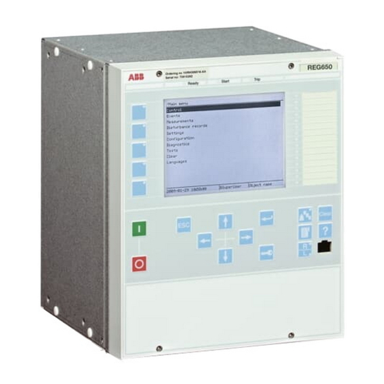
Section 4 1MRK 502 034-UEN - Local Human-Machine-Interface LHMI Operation principle 4.5.1 Local HMI GUID-23A12958-F9A5-4BF1-A31B-F69F56A046C7 V2 EN Figure 7: Local human-machine interface The LHMI of the IED contains the following elements: • Display (LCD) • Buttons • LED indicators • Communication port The LHMI is used for setting, monitoring and controlling . - Page 55 Section 4 1MRK 502 034-UEN - Local Human-Machine-Interface LHMI The display view is divided into four basic areas. GUID-97DA85DD-DB01-449B-AD1F-EEC75A955D25 V1 EN Figure 8: Display layout 1 Path 2 Content 3 Status 4 Scroll bar (appears when needed) • The path shows the current location in the menu structure. If the path is too long to be shown, it is truncated from the beginning, and the truncation is indicated with three dots.
- Page 56 Section 4 1MRK 502 034-UEN - Local Human-Machine-Interface LHMI GUID-1ECF507D-322A-4B94-B09C-49F6A0085384 V1 EN Figure 9: Truncated path The number before the function instance, for example 1:ETHFRNT, indicates the instance number. The function button panel shows on request what actions are possible with the function buttons.
-
Page 57: Leds
Section 4 1MRK 502 034-UEN - Local Human-Machine-Interface LHMI GUID-D20BB1F1-FDF7-49AD-9980-F91A38B2107D V1 EN Figure 11: Alarm LED panel The function button and alarm LED panels are not visible at the same time. Each panel is shown by pressing one of the function buttons or the Multipage button. Pressing the ESC button clears the panel from the display. - Page 58 Section 4 1MRK 502 034-UEN - Local Human-Machine-Interface LHMI GUID-23A12958-F9A5-4BF1-A31B-F69F56A046C7 V2 EN Figure 12: LHMI keypad Technical Manual...
- Page 59 Section 4 1MRK 502 034-UEN - Local Human-Machine-Interface LHMI GUID-5BF45085-F0E8-4FCB-A941-A2E7FE197EC6 V2 EN Figure 13: LHMI keypad with object control, navigation and command push- buttons and RJ-45 communication port 1...5 Function button Close Open Escape Left Down Right Enter Remote/Local Uplink LED Not in use Multipage Menu...
-
Page 60: Led
Section 4 1MRK 502 034-UEN - Local Human-Machine-Interface LHMI Communication port 4.5.2 4.5.2.1 Functionality The function blocks LEDGEN and GRP1_LEDx, GRP2_LEDx and GRP3_LEDx (x=1-15) controls and supplies information about the status of the indication LEDs. The input and output signals of the function blocks are configured with PCM600. The input signal for each LED is selected individually using SMT or ACT. - Page 61 Section 4 1MRK 502 034-UEN - Local Human-Machine-Interface LHMI disturbance is defined to end a settable time after the reset of the activated input signals or when the maximum time limit has elapsed. Acknowledgment/reset • From local HMI • The active indications can be acknowledged/reset manually. Manual acknowledgment and manual reset have the same meaning and is a common signal for all the operating sequences and LEDs.
- Page 62 Section 4 1MRK 502 034-UEN - Local Human-Machine-Interface LHMI = No indication = Steady light = Flash = Green = Red = Yellow IEC09000311.vsd IEC09000311 V1 EN Figure 14: Symbols used in the sequence diagrams Sequence 1 (Follow-S) This sequence follows all the time, with a steady light, the corresponding input signals.
- Page 63 Section 4 1MRK 502 034-UEN - Local Human-Machine-Interface LHMI the signal is not present any more. If the signal is still present after acknowledgment it gets a steady light. Activating signal Acknow. en01000231.vsd IEC01000231 V1 EN Figure 17: Operating sequence 3 (LatchedAck-F-S) When an acknowledgment is performed, all indications that appear before the indication with higher priority has been reset, will be acknowledged, independent of if the low priority indication appeared before or after acknowledgment.
- Page 64 Section 4 1MRK 502 034-UEN - Local Human-Machine-Interface LHMI Activating signal GREEN Activating signal YELLOW Activating signal RED Acknow. IEC09000314-1-en.vsd IEC09000314 V1 EN Figure 19: Operating sequence 3, three colors involved, alternative 1 If an indication with higher priority appears after acknowledgment of a lower priority indication the high priority indication will be shown as not acknowledged according to Figure...
- Page 65 Section 4 1MRK 502 034-UEN - Local Human-Machine-Interface LHMI Activating signal Reset IEC01000235_2_en.vsd IEC01000235 V2 EN Figure 21: Operating sequence 5 (LatchedColl-S) That means if an indication with higher priority has reset while an indication with lower priority still is active at the time of reset, the LED will change color according to Figure Activating...
- Page 66 Section 4 1MRK 502 034-UEN - Local Human-Machine-Interface LHMI Disturbance tRestart Activating signal 1 Activating signal 2 LED 1 LED 2 Automatic reset Manual reset IEC01000239_2-en.vsd IEC01000239 V2 EN Figure 23: Operating sequence 6 (LatchedReset-S), two indications within same disturbance Figure 24 shows the timing diagram for a new indication after tRestart time has elapsed.
- Page 67 Section 4 1MRK 502 034-UEN - Local Human-Machine-Interface LHMI Figure 25 shows the timing diagram when a new indication appears after the first one has reset but before tRestart has elapsed. Disturbance tRestart Activating signal 1 Activating signal 2 LED 1 LED 2 Automatic reset...
-
Page 68: Function Keys
Section 4 1MRK 502 034-UEN - Local Human-Machine-Interface LHMI 4.5.3 Function keys 4.5.3.1 Functionality Local Human-Machine-Interface (LHMI) has five function buttons, directly to the left of the LCD, that can be configured either as menu shortcut or control buttons. Each button has an indication LED that can be configured in the application configuration. - Page 69 Section 4 1MRK 502 034-UEN - Local Human-Machine-Interface LHMI Input value Output value IEC09000331_1_en.vsd IEC09000331 V1 EN Figure 28: Sequence diagram for Mode 1 Mode 2 (PULSED) In this mode the output will be high for as long as the setting pulse time. After this time the output will go back to 0.
-
Page 71: Section 5 Differential Protection
Section 5 1MRK 502 034-UEN - Differential protection Section 5 Differential protection Transformer differential protection 5.1.1 Functionality The Transformer differential protection, two-winding (T2WPDIF) and Transformer differential protection, three-winding (T3WPDIF) are provided with internal CT ratio matching and vector group compensation and settable, zero sequence current elimination. -
Page 72: Transformer Differential Protection T3Wpdif
Section 5 1MRK 502 034-UEN - Differential protection Stabilization is included for inrush currents as well as for overexcitation condition. Adaptive stabilization is also included for system recovery inrush and CT saturation for external faults. A high set unrestrained differential current protection is included for a very high speed tripping at a high internal fault currents. -
Page 73: Settings
Section 5 1MRK 502 034-UEN - Differential protection Table 17: T3WPDIF Output signals Name Type Description TRIP BOOLEAN General trip signal TRIPRES BOOLEAN Trip signal from restrained differential protection TRIPUNRE BOOLEAN Trip signal from unrestrained differential protection TRNSUNR BOOLEAN Trip signal from unrestrained negative sequence differential protection TRNSSENS BOOLEAN... - Page 74 Section 5 1MRK 502 034-UEN - Differential protection Name Values (Range) Unit Step Default Description I2/I1Ratio 5.0 - 100.0 15.0 Maximum ratio of 2nd harmonic to fundamental harmonic differential current I5/I1Ratio 5.0 - 100.0 25.0 Maximum ratio of 5th harmonic to fundamental harmonic differential current CrossBlockEn Operation Off/On for cross-block logic...
-
Page 75: Monitored Data
Section 5 1MRK 502 034-UEN - Differential protection Name Values (Range) Unit Step Default Description ClockNumberW3 0 [0 deg] 5 [150 deg lag] Phase displacement between W3 & 1 [30 deg lag] W1=HV winding, hour notation 2 [60 deg lag] 3 [90 deg lag] 4 [120 deg lag] 5 [150 deg lag]... -
Page 76: Function Calculation Principles
Section 5 1MRK 502 034-UEN - Differential protection The main CTs are normally supposed to be star connected. The main CTs can be earthed in anyway (that is, either "ToObject" or "FromObject"). However internally the differential function will always use reference directions towards the protected transformer as shown in figure 32. -
Page 77: Fundamental Frequency Differential Currents
Section 5 1MRK 502 034-UEN - Differential protection 5.1.3.2 Fundamental frequency differential currents The fundamental frequency differential current is a vectorial sum (sum of fundamental frequency phasors) of the individual phase currents from different side of the protected power transformer. Before any differential current can be calculated, the power transformer phase shift, and its transformation ratio, must be allowed for. - Page 78 Section 5 1MRK 502 034-UEN - Differential protection é ù é 1_ 1 ù é ù é ù Un W Un W ê ú ê ú ê ú ê ú × × × × × A IL 2 _ 1 ê...
- Page 79 Section 5 1MRK 502 034-UEN - Differential protection When the end user enters all these parameters, transformer differential function automatically calculates off-line the matrix coefficients. During this calculations the following rules are used: For the phase reference, the first winding with set star (Y) connection is always used.
- Page 80 Section 5 1MRK 502 034-UEN - Differential protection Table 21: Matrices for differential current calculation Matrix with Zero Sequence Matrix with Zero Sequence Reduction set to On Reduction set to Off Matrix for Reference Winding é ù é ù 1 0 0 ê...
- Page 81 Section 5 1MRK 502 034-UEN - Differential protection Matrix with Zero Sequence Matrix with Zero Sequence Reduction set to On Reduction set to Off Matrix for winding with 120° é ù é ù 0 1 0 leading ê ú ê ú...
-
Page 82: Differential Current Alarm
Section 5 1MRK 502 034-UEN - Differential protection IL2_W1 is the fundamental frequency phase current in phase L2 on W1 side IL3_W1 is the fundamental frequency phase current in phase L3 on W1 side IL1_W2 is the fundamental frequency phase current in phase L1 on W2 side IL2_W2 is the fundamental frequency phase current in phase L2 on W2 side IL3_W2... -
Page 83: Elimination Of Zero Sequence Currents
Section 5 1MRK 502 034-UEN - Differential protection which are the candidates for the common bias current. The highest individual current contribution is taken as a common bias (restrain) current for all three phases. This "maximum principle" makes the differential protection more secure, with less risk to operate for external faults and in the same time brings more meaning to the breakpoint settings of the operate - restrain characteristic. -
Page 84: Restrained, And Unrestrained Limits Of The Differential Protection
Section 5 1MRK 502 034-UEN - Differential protection 5.1.3.6 Restrained, and unrestrained limits of the differential protection Power transformer differential protection function uses two limits, to which actual magnitudes of the three fundamental frequency differential currents are compared at each execution of the function. The unrestrained (that is, non-stabilized, "instantaneous") part of the differential protection is used for very high differential currents, where it should be beyond any doubt, that the fault is internal. - Page 85 Section 5 1MRK 502 034-UEN - Differential protection operate current [ times IBase ] Operate unconditionally UnrestrainedLimit Operate conditionally Section 1 Section 2 Section 3 SlopeSection3 IdMin SlopeSection2 Restrain EndSection1 restrain current [ times IBase ] EndSection2 en05000187-2.vsd IEC05000187 V2 EN Figure 33: Description of the restrained, and the unrestrained operate characteristics...
-
Page 86: Fundamental Frequency Negative Sequence Differential Currents
Section 5 1MRK 502 034-UEN - Differential protection Section 2: In section 2, a certain minor slope is introduced which is supposed to cope with false differential currents proportional to higher than normal currents through the current transformers. Section 3: The more pronounced slope in section 3 is designed to result in a higher tolerance to substantial current transformer saturation at high through-fault currents, which may be expected in this section. - Page 87 Section 5 1MRK 502 034-UEN - Differential protection é ù é ù é ù é ù é ù INS W INS W ê ú ê ú ê ú ê ú ê ú Ur W × × × × × × ×...
-
Page 88: Internal/External Fault Discriminator
Section 5 1MRK 502 034-UEN - Differential protection shift and transferred to the power transformer W1 side. These negative sequence current contributions are phasors, which are further used in directional comparisons, made in order to characterize a fault as internal or external. See section "Internal/external fault discriminator"... - Page 89 Section 5 1MRK 502 034-UEN - Differential protection internal/external fault discriminator is shown in figure 34, where the directional characteristic is defined by two setting parameters: IMinNegSeq NegSeqROA 90 deg 120 deg If one or the Internal/external other of fault boundary currents is too low, then no measurement...
- Page 90 Section 5 1MRK 502 034-UEN - Differential protection If the above condition concerning magnitudes is fulfilled, the internal/external fault discriminator compares the relative phase angle between the negative sequence current contributions from the W1 and W2 sides of the power transformer using the following two rules: •...
- Page 91 Section 5 1MRK 502 034-UEN - Differential protection "steady state" for HV side neg. seq. phasor 0.1 kA 0.2 kA 0.3 kA 0.4 kA "steady state" for LV side neg. seq. phasor Contribution to neg. seq. differential current from HV side Contribution to neg.
-
Page 92: Unrestrained, And Sensitive Negative Sequence Protections
Section 5 1MRK 502 034-UEN - Differential protection Dire ctiona l Compa ris on Crite rion: Inte rna l fa ult a s s e e n from the HV s ide e xcurs ion from 0 de gre e s due to CT 35 ms s a tura tion... - Page 93 Section 5 1MRK 502 034-UEN - Differential protection If the same fault has been positively recognized as internal, then the unrestrained negative sequence differential protection places its own trip request. If the bias current is higher than 110% IBase of the power transformer winding W1, then any block signals by the harmonic and/or waveform criteria, which can block the traditional differential protection are overridden, and the differential protection operates quickly without any further delay.
-
Page 94: Instantaneous Differential Currents
Section 5 1MRK 502 034-UEN - Differential protection 5.1.3.10 Instantaneous differential currents The instantaneous differential currents are calculated from the instantaneous values of the input currents in order to perform the harmonic analysis and waveform analysis upon each one of them (see section "Harmonic and waveform block criteria"... -
Page 95: Switch Onto Fault Feature
Section 5 1MRK 502 034-UEN - Differential protection IEC05000343 V1 EN Figure 37: Inrush currents to a transformer as seen by a protective IED. Typical is a high amount of the 2 harmonic, and intervals of low current, and low rate-of-change of current within each period. Cross-blocking between phases Basic definition of the cross-blocking is that one of the three phases can block operation (that is,tripping) of the other two phases due to the harmonic pollution of... -
Page 96: Logic Diagram
Section 5 1MRK 502 034-UEN - Differential protection energized, the magnetic density in the iron core will be low and high sinusoidal currents will flow from the very beginning. The waveform block algorithm will in such a case remove all its three block signals in a very short interval of time. A quick reset of the waveblock criterion will temporarily disable the second harmonic blocking feature within the differential function. - Page 97 Section 5 1MRK 502 034-UEN - Differential protection Figure shows how internal treatment of measured currents is done in case of two- winding transformer. The following currents are inputs to the power transformer differential protection function. They must all be expressed in true power system (primary) A, that is, as measured.
- Page 98 Section 5 1MRK 502 034-UEN - Differential protection BLKUNRES IdUnre TRIPUNREL1 b>a IDL1MAG IBIAS STL1 BLOCK BLKRES TRIPRESL1 IDL1 BLK2HL1 Harmonic Wave BLKWAVL1 block BLK5HL1 Harmonic Cross Block Cross Block to L2 or L3 from L2 or L3 OpCrossBlock=On en06000545.vsd IEC06000545 V1 EN Figure 39: Transformer differential protection simplified logic diagram for...
- Page 99 Section 5 1MRK 502 034-UEN - Differential protection TRIPRESL1 TRIPRESL2 TRIPRES TRIPRESL3 TRIPUNREL1 TRIPUNREL2 TRIPUNRE TRIPUNREL3 TRIP TRNSSENS TRNSUNR en05000278.vsd IEC05000278 V1 EN Figure 41: Transformer differential protection internal grouping of tripping signals IEC05000279-TIFF V1 EN Figure 42: Transformer differential protection internal grouping of logical signals Logic in figures 39, 40, can be summarized as follows: The three fundamental frequency differential currents are applied in a phase-...
- Page 100 Section 5 1MRK 502 034-UEN - Differential protection respective block signals, a restrained trip TRIPRES and common trip TRIP are issued If a start signal is issued in a phase, and the fault has been classified as internal, then any eventual block signals are overridden and a unrestrained negative-sequence trip TRNSUNR and common trip TRIP are issued without any further delay.
-
Page 101: Technical Data
Section 5 1MRK 502 034-UEN - Differential protection 5.1.4 Technical data Table 22: T2WPDIF, T3WPDIF technical data Function Range or value Accuracy Operating characteristic Adaptable ± 1.0% of Ir for I < Ir ± 1.0% of Ir for I > Ir Reset ratio >94% IBase on... -
Page 102: Introduction
Section 5 1MRK 502 034-UEN - Differential protection 5.2.2 Introduction The 1Ph High impedance differential protection HZPDIF function can be used when the involved CT cores have the same turn ratio and similar magnetizing characteristics. It utilizes an external summation of the currents in the interconnected CTs and a series resistor and a voltage dependent resistor externally to the IED. -
Page 103: Settings
Section 5 1MRK 502 034-UEN - Differential protection 5.2.5 Settings Table 25: HZPDIF Group settings (basic) Name Values (Range) Unit Step Default Description Operation Operation Off / On U>Alarm 2 - 500 Alarm voltage level in volts on CT secondary side tAlarm 0.000 - 60.000 0.001... -
Page 104: Technical Data
Section 5 1MRK 502 034-UEN - Differential protection IEC05000301 V1 EN Figure 45: Logic diagram for 1Ph High impedance differential protection HZPDIF 5.2.8 Technical data Table 27: HZPDIF technical data Function Range or value Accuracy Operate voltage (20-400) V ± 1.0% of I I=U/R Reset ratio >95%... -
Page 105: Functionality
Section 5 1MRK 502 034-UEN - Differential protection 5.3.2 Functionality Short circuit between the phases of the stator windings causes normally very large fault currents. The short circuit gives risk of damages on insulation, windings and stator iron core. The large short circuit currents cause large forces, which can cause damage even to other components in the power plant, such as turbine and generator- turbine shaft. -
Page 106: Function Block
Section 5 1MRK 502 034-UEN - Differential protection 5.3.3 Function block GENPDIF I3PNCT* TRIP I3PTCT* TRIPRES BLOCK TRIPUNRE BLKRES TRNSUNR BLKUNRES TRNSSENS BLKNSUNR START BLKNSSEN BLKH DESENSIT OPENCT OPENCTAL IDL1MAG IDL2MAG IDL3MAG IDNSMAG IBIAS IEC07000025_2_en.vsd IEC07000025 V2 EN Figure 46: GENPDIF function block 5.3.4 Signals... -
Page 107: Settings
Section 5 1MRK 502 034-UEN - Differential protection Name Type Description OPENCTAL BOOLEAN Open CT Alarm output signal. Issued after a delay ... IDL1MAG REAL Fund. freq. differential current, phase L1; in primary A IDL2MAG REAL Fund. freq. differential current, phase L2; in primary A IDL3MAG REAL... -
Page 108: Operation Principle
Section 5 1MRK 502 034-UEN - Differential protection Name Values (Range) Unit Step Default Description OperDCBiasing Operation DC biasing On / Off OpenCTEnable Open CT detection feature Off/On tOCTAlarmDelay 0.100 - 10.000 0.001 1.000 Open CT: time to alarm if an open CT is detected, in sec tOCTResetDelay 0.100 - 10.000... -
Page 109: Function Calculation Principles
Section 5 1MRK 502 034-UEN - Differential protection Numerical IEDs have brought a large number of advantages and new functionality to the protective relaying. One of the benefits is the simplicity and accuracy of calculating symmetrical components from individual phase quantities. Within the firmware of a numerical IED, it is no more difficult to calculate negative-sequence components than it is to calculate zero-sequence components. - Page 110 Section 5 1MRK 502 034-UEN - Differential protection Idiff [(Re( 1 IL n IL t 1 )) (Im( 1 IL n IL t 1 )) ] (Equation 26) EQUATION2316 V2 EN One common fundamental frequency bias current is used. The bias current is the magnitude of the highest measured current in the protected circuit.
- Page 111 Section 5 1MRK 502 034-UEN - Differential protection IL1n IL1t External fault: IL1n = - IL1t IL1t IL1n Idiff = 0 en07000019-2.vsd IEC07000019 V2 EN Figure 49: External fault Generator differential protection GENPDIF function uses two mutually independent characteristics to which magnitudes of the three fundamental frequency RMS differential currents are compared at each execution of the differential protection function.
- Page 112 Section 5 1MRK 502 034-UEN - Differential protection Ioperate × slope 100% Irestrain (Equation 28) EQUATION1246 V1 EN Note that both slopes are calculated from the characteristics break points. The operate-restrain characteristic is tailor-made, in other words, it can be constructed by the user.
- Page 113 Section 5 1MRK 502 034-UEN - Differential protection operate current [ times IBase ] Operate unconditionally UnrestrainedLimit Operate conditionally Section 1 Section 2 Section 3 SlopeSection3 TempIdMin IdMin SlopeSection2 Restrain EndSection1 restrain current [ times IBase ] EndSection2 en06000637.vsd IEC06000637 V2 EN Figure 51: Operate-restrain characteristic GENPDIF can also be temporarily ‘desensitized’...
-
Page 114: Supplementary Criteria
Section 5 1MRK 502 034-UEN - Differential protection 5.3.6.3 Supplementary criteria To relieve the burden of constructing an exact optimal operate-restrain characteristic, two special features supplement the basic stabilized differential protection function, making Generator differential protection GENPDIF a very reliable one. The supplementary criteria are: •... - Page 115 Section 5 1MRK 502 034-UEN - Differential protection • If the two negative sequence currents, as seen by the differential relay, flow in the same direction (that is with the CTs oriented as in figure 47), the fault is internal. If the two negative sequence currents flow in opposite directions, the fault is external.
- Page 116 Section 5 1MRK 502 034-UEN - Differential protection 90 deg 120 deg NegSeqROA Angle could not be (Relay Operate Angle) measured. One or both currents too small Internal fault region 180 deg 0 deg IminNegSeq External fault region Internal / external fault boundary.
-
Page 117: Harmonic Restrain
Section 5 1MRK 502 034-UEN - Differential protection 5.3.6.4 Harmonic restrain Harmonic restrain is the classical restrain method traditionally used with power transformer differential protections. The goal there was to prevent an unwanted trip command due to magnetizing inrush currents at switching operations, due to magnetizing currents at over-voltages, or external faults. - Page 118 Section 5 1MRK 502 034-UEN - Differential protection TRIP Signals Start Phasors IL1N, IL2N,IL3N Magnitude phase Idiff and Ibias selective Calculation Diff.prot. characteristic Idiff and Ibias Phasors IL1T, IL2T,IL3T START Signals BLOCK Signals Samples IL1N, IL2N,IL3N Harm. INTFAULT Hamonic Calculation Samples Idiff Block Start and...
- Page 119 Section 5 1MRK 502 034-UEN - Differential protection BLKUNRES IdUnre TRIPUNREL1 b>a IDL1MAG IBIAS STL1 BLOCK BLKRES TRIPRESL1 INTFAULT 2nd and Harmonic Cross Block from L2 or L3 OpCrossBlock=On en07000020.vsd IEC07000020 V2 EN Figure 54: Generator differential logic diagram 1. Internal/ Neg.Seq.
-
Page 120: Technical Data
Section 5 1MRK 502 034-UEN - Differential protection STL1 STL2 START STL3 BLKHL1 BLKHL2 BLKH BLKHL3 en07000022.vsd IEC07000022 V1 EN Figure 56: Generator differential logic diagram 3. TRIPRESL1 TRIPRESL2 TRIPRES TRIPRESL3 TRIPUNREL1 TRIPUNREL2 TRIPUNRE TRIPUNREL3 TRIP TRNSSENS TRNSUNR en07000023.vsd IEC07000023 V1 EN Figure 57: Generator differential logic diagram 4. - Page 121 Section 5 1MRK 502 034-UEN - Differential protection Function Range or value Accuracy Reset time, unrestrained function 40 ms typically at 5 to 0 x set level Operate time, negative sequence 15 ms typically at 0 to unrestrained function 5 x set level Critical impulse time, unrestrained function 2 ms typically at 0 to 5 x set level...
-
Page 123: Section 6 Impedance Protection
Section 6 1MRK 502 034-UEN - Impedance protection Section 6 Impedance protection Underimpedance protection for generators and transformers ZGPDIS 6.1.1 Identification Function description IEC 61850 IEC 60617 ANSI/IEEE C37.2 identification identification device number Underimpedance protection for ZGPDIS generators and transformers 6.1.2 Functionality The underimpedance protection for generators and transformers ZGPDIS, has the... -
Page 124: Function Block
Section 6 1MRK 502 034-UEN - Impedance protection 6.1.3 Function block ZGPDIS I3P* TRIP U3P* TRZ1 BLOCK TRZ2 BLKZ TRZ3 LDCND START STZ1 STZ2 STZ3 IEC10000122-1-en.vsd IEC10000122 V1 EN Figure 59: ZGPDIS function block 6.1.4 Signals Table 34: ZGPDIS Input signals Name Type Default... -
Page 125: Settings
Section 6 1MRK 502 034-UEN - Impedance protection 6.1.5 Settings Table 36: ZGPDIS Group settings (basic) Name Values (Range) Unit Step Default Description Operation Operation Off/On ImpedanceAng 0 - 90 Impedance angle in degrees, common for all zones OpModeZ1 Disable-Zone Disable-Zone Operation mode of zone 1 Enable-Zone... -
Page 126: Impedance Characteristic
Section 6 1MRK 502 034-UEN - Impedance protection 6.1.6.2 Impedance characteristic The distance function consists of three zones. Each zone is self polarized offset mho characteristics with reverse offset. The operating characteristic is in accordance to figure 60. Mho, zone3 Mho, zone2 Mho, zone1 IEC09000172_1_en.vsd... -
Page 127: Theory Of Operation
Section 6 1MRK 502 034-UEN - Impedance protection arguments by the parameter ImpedanceAng. The setting ImpedanceAng is common for all three zones. ImpedanceAng IEC10000176-1-en.vsd IEC10000176 V1 EN Figure 61: Mho, offset mho characteristic for Zone 1 with setting parameters Z1Fwd, Z1Rev and ImpedanceAng The measuring loops can be time delayed individually by setting the parameter tZx (where x is 1-3 depending on selected zone). - Page 128 Section 6 1MRK 502 034-UEN - Impedance protection The characteristic for offset mho is a circle where two points on the circle are the setting parameters ZxFwd and ZxRev. The vector ZxFwd in the impedance plane has the settable angle ImpadenceAng and the angle for ZxRev is ImpedanceAng +180°.
-
Page 129: Technical Data
Section 6 1MRK 502 034-UEN - Impedance protection 6.1.7 Technical data Table 38: ZGPDIS technical data Function Range or value Accuracy Number of zones Forward positive sequence impedance (0.005-3000.000) Ω/ ± 2.0% static accuracy phase Conditions: • Voltage range: (0.1-1.1) x U •... -
Page 130: Function Block
Section 6 1MRK 502 034-UEN - Impedance protection 6.2.3 Function block LEXPDIS I3P* TRIP U3P* TRZ1 BLOCK TRZ2 BLKTRZ1 START BLKTRZ2 STZ1 STZ2 XOHM XPERCENT ROHM RPERCENT IEC07000031_2_en.vsd IEC07000031 V2 EN Figure 63: LEXPDIS function block 6.2.4 Signals Table 39: LEXPDIS Input signals Name Type... -
Page 131: Settings
Section 6 1MRK 502 034-UEN - Impedance protection 6.2.5 Settings Table 41: LEXPDIS Group settings (basic) Name Values (Range) Unit Step Default Description Operation Operation Off / On OperationZ1 Operation Off/On zone Z1 XoffsetZ1 -1000.00 - 1000.00 0.01 -10.00 Offset of Z1 circle top point along X axis in % of Zbase Z1diameter 0.01 - 3000.00... - Page 132 Section 6 1MRK 502 034-UEN - Impedance protection There are three characteristics in LEXPDIS protection as shown in figure 64. Naimly: • Offset mho circle for Z1 • Offset mho circle for Z2 • Directional blinder Underexitation protection Underexcitation Protection Restrain area Restrain area Directional...
- Page 133 Section 6 1MRK 502 034-UEN - Impedance protection Offset XoffsetZ1 Z (apparent impedance) Z1 = Z - (XoffsetZ1 + Z1diameter Z1diameter/2) Z1 or Z2 en06000456-2.vsd IEC06000456 V2 EN Figure 65: Zone measurement in LEXPDIS protection function The impedance Z1 is constructed out from the measured apparent impedance Z and the impedance corresponding to the centre point of the impedance characteristic (Z1 or Z2).
- Page 134 Section 6 1MRK 502 034-UEN - Impedance protection Underexcitation Protection Restrain area XoffsetDirLine DirAngle Z (apparent impedance) en06000457.vsd IEC06000457 V1 EN Figure 66: Impedance constructed as XoffsetDirLine in LEXPDIS protection LEXPDIS function is schematically described in figure 67. Positive Z in startZ1 TripZ1 sequence...
-
Page 135: Technical Data
Section 6 1MRK 502 034-UEN - Impedance protection 6.2.7 Technical data Table 44: LEXPDIS technical data Function Range or value Accuracy X offset of Mho top point (–1000.00–1000.00)% of Z ± 2.0% of Ur/Ir Base Diameter of Mho circle (0.00–3000.00)% of Z ±... -
Page 136: Function Block
Section 6 1MRK 502 034-UEN - Impedance protection 6.3.3 Function block IEC10000106 V1 EN Figure 68: OOSPPAM function block 6.3.4 Signals Table 45: OOSPPAM Input signals Name Type Default Description GROUP Group connection for three-phase current input SIGNAL GROUP Group connection for three-phase voltage input SIGNAL BLOCK BOOLEAN... -
Page 137: Settings
Section 6 1MRK 502 034-UEN - Impedance protection 6.3.5 Settings Table 47: OOSPPAM Group settings (basic) Name Values (Range) Unit Step Default Description Operation Operation On / Off OperationZ1 Operation Zone1 On / Off ReachZ1 1.00 - 100.00 0.01 50.00 Percentage part of total forward impedance;... -
Page 138: Operation Principle
Section 6 1MRK 502 034-UEN - Impedance protection 6.3.6 Operation principle General Under balanced and stable conditions, a generator operates with a constant rotor angle (power angle), delivering to the power system active electrical power which is approximately equal to the mechanical input on the generator axis. The currents and voltages are constant and stable. - Page 139 Section 6 1MRK 502 034-UEN - Impedance protection centre of oscillation is where the locus of the complex impedance Z(R, X) crosses the (impedance) line connecting the points SE (Sending End), and RE (Receiving End). The point on the SE – RE line where the trajectory of Z(R, X) crosses the impedance line can change with time and is mainly a function of the internal induced voltages at both ends of the equivalent two-machine system, that is, at points SE and RE.
-
Page 140: Lens Characteristic
Section 6 1MRK 502 034-UEN - Impedance protection X [Ohm] Z(R,X) 20 ms fault relay after line out - - - - - - - - - - pre-fault - - - - - - - - - zone 2 - - - Z(R,X) - - -... - Page 141 Section 6 1MRK 502 034-UEN - Impedance protection Position of the OOS relay is the origin of - - - - - - - - - the R - X plane - - - - - - Zone 2 X-line determined Zline by the...
-
Page 142: Detecting An Out-Of-Step Condition
Section 6 1MRK 502 034-UEN - Impedance protection voltage level. The impedances from the position of the out-of-step protection in the direction of the normal load flow can be taken as forward. The out-of-step relay, as in Figure 73 looks into the system and the impedances in that direction are forward impedances: •... -
Page 143: Maximum Slip Frequency
Section 6 1MRK 502 034-UEN - Impedance protection fault has been cleared. Transition of the measured Z from point 1 to point 2 takes approximately 20 ms, due to Fourier filters. The complex impedance then travels in the direction from the right to the left, and exits the lens on the opposite side. When the complex impedance exits the lens on the side opposite to its entrance, the 1st pole- slip has already occurred and more pole-slips can be expected if the generator is not disconnected. -
Page 144: Taking Care Of The Circuit Breaker Safety
Section 6 1MRK 502 034-UEN - Impedance protection second pole-slip, if the protected machine is not already disconnected after the first pole-slip. The measured value of slipsPerSecond (SLIPFREQ) is equal to the average slip-frequency of the machine between the last two successive pole-slips. 6.3.6.4 Taking care of the circuit breaker safety Although out-of-step events are relatively rare, the out-of-step protection should... - Page 145 Section 6 1MRK 502 034-UEN - Impedance protection X[Ohm] RE - Receiving End (infinite bus) trip region loci of Z(R, X) no trip region here rotor here angle rotor angle no trip is -90° is +90° rotor angle region = ±180° no trip relay region...
-
Page 146: Design
Section 6 1MRK 502 034-UEN - Impedance protection 6.3.6.5 Design When the complex impedance Z(R, X) enters the limit-of-reach region, the algorithm determines the direction impedance Z moves, that is, the direction the lens is traversed and measures the time taken to traverse the lens from one side to the other. -
Page 147: Technical Data
Section 6 1MRK 502 034-UEN - Impedance protection 6.3.7 Technical data Table 51: OOSPPAM technical data Function Range or value Accuracy Remark VOLTAGE 0.1 – 2.0 UBase Better than ±1.5 % of true Better than ±0.5 % at nominal value or 1 % of rated, voltage whichever is greater CURRENT... -
Page 148: Function Block
Section 6 1MRK 502 034-UEN - Impedance protection 6.4.3 Function block LEPDIS I3P* STCNDLE U3P* BLOCK IEC10000119-1-en.vsd IEC10000119 V1 EN Figure 77: LEPDIS function block 6.4.4 Signals Table 52: LEPDIS Input signals Name Type Default Description GROUP Three phase group signal for current inputs SIGNAL GROUP Three phase group signal for voltage inputs... -
Page 149: Load Encroachment
Section 6 1MRK 502 034-UEN - Impedance protection The difference compared to the distance zone measuring function is in the combination of measuring quantities (currents and voltages) for different types of faults. The current start condition STCNDLE is based on the following criteria: Residual current criteria Load encroachment characteristic The STCNDLE output is non-directional. -
Page 150: Simplified Logic Diagrams
Section 6 1MRK 502 034-UEN - Impedance protection 6.4.6.2 Simplified logic diagrams Figure schematically presents the creation of the phase-to-phase operating conditions. L1L2 Block I ³ 0.05 & & & ³ × phmax STCNDLE & Bool to BLOCK integer & I <... -
Page 151: Section 7 Current Protection
Section 7 1MRK 502 034-UEN - Current protection Section 7 Current protection Four step phase overcurrent protection OC4PTOC 7.1.1 Identification Function description IEC 61850 IEC 60617 ANSI/IEEE C37.2 identification identification device number Four step phase overcurrent protection OC4PTOC 51/67 3I> TOC-REVA V1 EN 7.1.2 Functionality... -
Page 152: Signals
Section 7 1MRK 502 034-UEN - Current protection 7.1.4 Signals Table 57: OC4PTOC Input signals Name Type Default Description GROUP Three phase group signal for current inputs SIGNAL GROUP Three phase group signal for voltage inputs SIGNAL BLOCK BOOLEAN Block of function BLKST1 BOOLEAN Block of step 1... -
Page 153: Settings
Section 7 1MRK 502 034-UEN - Current protection 7.1.5 Settings Table 59: OC4PTOC Group settings (basic) Name Values (Range) Unit Step Default Description Operation Operation Off / On DirMode1 Non-directional Directional mode of step 1 off / non- Non-directional directional / forward / reverse Forward Reverse Characterist1... -
Page 154: Monitored Data
Section 7 1MRK 502 034-UEN - Current protection Name Values (Range) Unit Step Default Description Characterist4 ANSI Ext. inv. ANSI Def. Time Selection of time delay curve type for ANSI Very inv. step 4 ANSI Norm. inv. ANSI Def. Time L.T.E. -
Page 155: Operation Principle
Section 7 1MRK 502 034-UEN - Current protection 7.1.7 Operation principle The Four step overcurrent protection function OC4PTOC is divided into three different sub-functions, one for each step. For each step x , where x is step 1, 2, 3 and 4, an operation mode is set by DirModex: Off/Non-directional/Forward/ Reverse. - Page 156 Section 7 1MRK 502 034-UEN - Current protection voltage is a combination of the apparent voltage (85%) and a memory voltage (15%). The following combinations are used. Phase-phase short circuit: refL L dirL L (Equation 33) EQUATION1449 V1 EN refL L dirL L (Equation 34) EQUATION1450 V1 EN...
- Page 157 Section 7 1MRK 502 034-UEN - Current protection IEC09000636_1_vsd IEC09000636 V1 EN Figure 81: Directional characteristic of the phase overcurrent protection 1 RCA = Relay characteristic angle 55° 2 ROA = Relay operating angle 80° 3 Reverse 4 Forward If no blockings are given the start signals will start the timers of the step. The time characteristic for step 1 and 4 can be chosen as definite time delay or inverse time characteristic.
-
Page 158: Technical Data
Section 7 1MRK 502 034-UEN - Current protection 7.1.8 Technical data Table 62: OC4PTOC technical data Function Setting range Accuracy lBase Operate current (5-2500)% of ± 1.0% of I at I ≤ I ± 1.0% of I at I > I Reset ratio >... -
Page 159: Function Block
Section 7 1MRK 502 034-UEN - Current protection All IEC and ANSI time delayed characteristics are available. The directional function is voltage polarized, current polarized or dual polarized. EF4PTOC can be set directional or non-directional independently for each of the steps. -
Page 160: Settings
Section 7 1MRK 502 034-UEN - Current protection Name Type Description TRIN4 BOOLEAN Trip signal from step 4 START BOOLEAN General start signal STIN1 BOOLEAN Start signal step 1 STIN2 BOOLEAN Start signal step 2 STIN3 BOOLEAN Start signal step 3 STIN4 BOOLEAN Start signal step 4... - Page 161 Section 7 1MRK 502 034-UEN - Current protection Name Values (Range) Unit Step Default Description Characterist1 ANSI Ext. inv. ANSI Def. Time Time delay curve type for step 1 ANSI Very inv. ANSI Norm. inv. ANSI Mod. inv. ANSI Def. Time L.T.E.
- Page 162 Section 7 1MRK 502 034-UEN - Current protection Name Values (Range) Unit Step Default Description DirMode4 Non-directional Directional mode of step 4 (off, non- Non-directional directional, forward, reverse) Forward Reverse Characterist4 ANSI Ext. inv. ANSI Def. Time Time delay curve type for step 4 ANSI Very inv.
-
Page 163: Monitored Data
Section 7 1MRK 502 034-UEN - Current protection 7.2.6 Monitored data Table 67: EF4PTOC Monitored data Name Type Values (Range) Unit Description REAL Operating current level UPol REAL Polarizing voltage level IPol REAL Polarizing current level UPOLIANG REAL Angle between polarizing voltage and operating current IPOLIANG... -
Page 164: Internal Polarizing
Section 7 1MRK 502 034-UEN - Current protection PCM600). In such case the pre-processing block will calculate 3I from the first three inputs into the pre-processing block by using the following formula: Iop 3I IL1 IL2 IL3 (Equation 39) EQUATION1874 V2 EN where: IL1, IL2 and IL3 are fundamental frequency phasors of three individual phase currents. - Page 165 Section 7 1MRK 502 034-UEN - Current protection The residual voltage is pre-processed by a discrete fourier filter. Thus, the phasor of the fundamental frequency component of the residual voltage is derived. This phasor is used together with the phasor of the operating current, in order to determine the direction to the earth fault (Forward/Reverse).
-
Page 166: External Polarizing For Earth-Fault Function
Section 7 1MRK 502 034-UEN - Current protection which will be then used, together with the phasor of the operating current, in order to determine the direction to the earth fault (Forward/Reverse). In order to enable current polarizing the magnitude of polarizing current shall be bigger than a minimum level defined by setting parameter IPolMin. -
Page 167: Four Residual Overcurrent Steps
Section 7 1MRK 502 034-UEN - Current protection 7.2.7.6 Four residual overcurrent steps Each overcurrent step uses operating quantity Iop (residual current) as measuring quantity. Each of the four residual overcurrent steps has the following built-in facilities: • Directional mode can be set to Off/Non-directional/Forward/Reverse. By this parameter setting the directional mode of the step is selected. -
Page 168: Directional Supervision Element With Integrated Directional Comparison Function
Section 7 1MRK 502 034-UEN - Current protection 7.2.7.7 Directional supervision element with integrated directional comparison function It shall be noted that at least one of the four residual overcurrent steps shall be set as directional in order to enable execution of the directional supervision element and the integrated directional comparison function. - Page 169 Section 7 1MRK 502 034-UEN - Current protection • Directional element will be internally enabled to operate as soon as Iop is bigger than 40% of IN>Dir and directional condition is fulfilled in set direction. • Relay characteristic angle AngleRCA, which defines the position of forward and reverse areas in the operating characteristic.
-
Page 170: Technical Data
Section 7 1MRK 502 034-UEN - Current protection STRV a>b REVERSE_Int STFW a>b IN>Dir FORWARD_Int FORWARD_Int AngleRCA polMethod=Voltage UPolMin polMethod=Dual UPol IPolMin polMethod=Current UTotPol IPol REVERSE_Int UIPol STAGE1_DIR_Int RNPol Complex STAGE2_DIR_Int Number STAGE3_DIR_Int XNPol STAGE4_DIR_Int BLOCK IEC07000067-4-en.vsd IEC07000067 V4 EN Figure 85: Simplified logic diagram for directional supervision element with integrated directional comparison step... -
Page 171: Sensitive Directional Residual Overcurrent And Power Protection Sdepsde
Section 7 1MRK 502 034-UEN - Current protection Function Range or value Accuracy Inverse characteristics, see 17 curve types See table 481, table table 481, table and table table UBase Minimum polarizing voltage (1–100)% of ± 0.5% of U Minimum polarizing current (2-100)% of IBase ±1.0% of I... -
Page 172: Function Block
Section 7 1MRK 502 034-UEN - Current protection 7.3.3 Function block SDEPSDE I3P* TRIP U3P* TRDIRIN BLOCK TRNDIN BLKUN TRUN START STDIRIN STNDIN STUN STFW STRV STDIR UNREL IEC08000036 V1 EN Figure 86: SDEPSDE function block 7.3.4 Signals Table 69: SDEPSDE Input signals Name Type... -
Page 173: Settings
Section 7 1MRK 502 034-UEN - Current protection 7.3.5 Settings Table 71: SDEPSDE Group settings (basic) Name Values (Range) Unit Step Default Description Operation Operation Off / On OpMode 3I0Cosfi 3I0Cosfi Selection of operation mode for protection 3I03U0Cosfi 3I0 and fi DirMode Forward Forward... -
Page 174: Monitored Data
Section 7 1MRK 502 034-UEN - Current protection Name Values (Range) Unit Step Default Description 0.00 - 2.00 0.01 1.00 IDMT time multiplier for non-directional residual overcurrent OpUN> Operation of non-directional residual overvoltage UN> 1.00 - 300.00 0.01 20.00 Set level for non-dir residual voltage, % of UBase 0.000 - 60.000 0.001... -
Page 175: Directional Residual Current Protection Measuring 3I Φ
Section 7 1MRK 502 034-UEN - Current protection 7.3.7.2 Directional residual current protection measuring 3I ·cos φ φ is defined as the angle between the residual current 3I and the reference voltage compensated with the set characteristic angle RCADir (φ=ang(3I )-ang(U ) ). - Page 176 Section 7 1MRK 502 034-UEN - Current protection For trip, both the residual current 3I ·cos φ and the release voltage 3U , must be larger than the set levels: INCosPhi> and UNRel>. When the function is activated binary output signals START and STDIRIN are activated.
-
Page 177: Cos Φ
Section 7 1MRK 502 034-UEN - Current protection RCADir = 0º Operate area Instrument transformer RCAcomp angle error Characteristic after angle compensation (to prot) (prim) en06000651.vsd IEC06000651 V2 EN Figure 90: Explanation of RCAComp 7.3.7.3 Directional residual power protection measuring 3I ·... -
Page 178: Directional Residual Current Protection Measuring 3I And Φ
Section 7 1MRK 502 034-UEN - Current protection The inverse time delay is defined as: × × × kSN (3I 3U cos (reference)) × × 3I 3U cos (measured) (Equation 44) EQUATION1942 V2 EN 7.3.7.4 Directional residual current protection measuring 3I and φ... -
Page 179: Directional Functions
Section 7 1MRK 502 034-UEN - Current protection 7.3.7.5 Directional functions For all the directional functions there are directional start signals STFW: fault in the forward direction, and STRV: start in the reverse direction. Even if the directional function is set to operate for faults in the forward direction a fault in the reverse direction will give the start signal STRV. - Page 180 Section 7 1MRK 502 034-UEN - Current protection STNDIN INNonDir> TRNDIN STUN UN> TRUN OpMODE=3I0cosfi IN> & INcosPhi> OpMODE=3I03U0cosfi STARTDIRIN & & INUNcosPhi> TRDIRIN & Phi in RCA +- ROA TimeChar = InvTime & OpMODE=3I0 and fi & TimeChar = DefTime DirMode = Forward &...
-
Page 181: Technical Data
Section 7 1MRK 502 034-UEN - Current protection 7.3.8 Technical data Table 74: SDEPSDE technical data Function Range or value Accuracy lBase Operate level for 3I ·cosj (0.25-200.00)% of ± 1.0% of I at I £ I directional residual overcurrent ±... -
Page 182: Thermal Overload Protection, Two Time Constants Trpttr
Section 7 1MRK 502 034-UEN - Current protection Function Range or value Accuracy Reset time, directional residual 170 ms typically at 2 to 0.5 x over current Critical impulse time non- 100 ms typically at 0 to 2 x I directional residual over current 20 ms typically at 0 to 10 x I Impulse margin time non-... -
Page 183: Function Block
Section 7 1MRK 502 034-UEN - Current protection 7.4.3 Function block TRPTTR I3P* TRIP BLOCK START COOLING ALARM1 RESET ALARM2 LOCKOUT WARNING IEC08000037 V1 EN Figure 93: TRPTTR function block 7.4.4 Signals TRPTTR is not provided with external temperature sensor in first release of 650 series. -
Page 184: Settings
Section 7 1MRK 502 034-UEN - Current protection 7.4.5 Settings Table 77: TRPTTR Group settings (basic) Name Values (Range) Unit Step Default Description Operation Operation Off / On IRef 10.0 - 1000.0 100.0 Reference current in % of IBase IBase1 30.0 - 250.0 100.0 Base current IBase1 without cooling... -
Page 185: Monitored Data
Section 7 1MRK 502 034-UEN - Current protection 7.4.6 Monitored data Table 79: TRPTTR Monitored data Name Type Values (Range) Unit Description TTRIP REAL Estimated time to trip (in min) TTRIPCAL INTEGER Calculated time status to trip: not active/long time/ active TRESCAL INTEGER... - Page 186 Section 7 1MRK 502 034-UEN - Current protection > Q final (Equation 46) EQUATION1172 V1 EN æ ö Q = Q × ç ÷ final è ø (Equation 47) EQUATION1173 V1 EN < Q final (Equation 48) EQUATION1174 V1 EN Q = Q ×...
- Page 187 Section 7 1MRK 502 034-UEN - Current protection After a trip, caused by the thermal overload protection, there can be a lockout to reconnect the tripped circuit. The output lockout signal LOCKOUT is activated when the temperature of the object is above the set lockout release temperature setting ResLo.
- Page 188 Section 7 1MRK 502 034-UEN - Current protection Final Temp START > TripTemp actual heat comtent Calculation of heat content Calculation of final temperature ALARM1 Actual Temp > Alarm1,Alarm2 ALARM2 Temp Current base used TRIP Actual Temp > TripTemp LOCKOUT Binary input: Forced cooling Management of...
-
Page 189: Technical Data
Section 7 1MRK 502 034-UEN - Current protection 7.4.8 Technical data Table 80: TRPTTR technical data Function Range or value Accuracy IBase Base current 1 and 2 (30–250)% of ± 1.0% of I Operate time: = load current before overload IEC 60255–8, class 5 + 200 occurs æ... -
Page 190: Function Block
Section 7 1MRK 502 034-UEN - Current protection exceed the user defined settings, the function is activated. These conditions increase the security of the back-up trip command. CCRBRF function can be programmed to give a three-phase re-trip of the own breaker to avoid unnecessary tripping of surrounding breakers at an incorrect initiation due to mistakes during testing. -
Page 191: Settings
Section 7 1MRK 502 034-UEN - Current protection 7.5.5 Settings Table 83: CCRBRF Group settings (basic) Name Values (Range) Unit Step Default Description Operation Operation Off / On FunctionMode Current Current Detection principle for back-up trip Contact Current&Contact BuTripMode 2 out of 4 1 out of 3 Back-up trip mode 1 out of 3... -
Page 192: Operation Principle
Section 7 1MRK 502 034-UEN - Current protection 7.5.7 Operation principle Breaker failure protection (CCRBRF) is initiated from protection trip command, either from protection functions within the IED or from external protection devices. The start signal is general for all three phases. A re-trip attempt can be made after a set time delay. -
Page 193: Technical Data
Section 7 1MRK 502 034-UEN - Current protection Internal logical signals STIL1, STIL2, STIL3 have logical value 1 when current in respective phase has magnitude larger than setting parameter IP>. Internal logical signal STN has logical value 1 when neutral current has magnitude larger than setting parameter IN>. -
Page 194: Function Block
Section 7 1MRK 502 034-UEN - Current protection zero sequence currents which cause thermal stress on rotating machines and can cause unwanted operation of zero sequence or negative sequence current functions. Normally the own breaker is tripped to correct such a situation. If the situation persists the surrounding breakers should be tripped to clear the unsymmetrical load situation. -
Page 195: Settings
Section 7 1MRK 502 034-UEN - Current protection 7.6.5 Settings Table 90: CCRPLD Group settings (basic) Name Values (Range) Unit Step Default Description Operation Operation Off / On tTrip 0.000 - 60.000 0.001 0.300 Time delay between trip condition and trip signal ContSel Contact function selection... - Page 196 Section 7 1MRK 502 034-UEN - Current protection circuit breaker Pole discordance signal from circuit breaker en05000287.vsd IEC05000287 V2 EN Figure 98: Pole discordance external detection logic This binary signal is connected to a binary input of the IED. The appearance of this signal will start a timer that will give a trip signal after the set time delay.
-
Page 197: Pole Discordance Signaling From Circuit Breaker
Section 7 1MRK 502 034-UEN - Current protection The BLOCK signal is a general purpose blocking signal of the pole discordance protection. It can be connected to a binary input in the IED in order to receive a block command from external devices or can be software connected to other internal functions in the IED itself in order to receive a block command from internal functions. -
Page 198: Technical Data
Section 7 1MRK 502 034-UEN - Current protection 7.6.8 Technical data Table 93: CCRPLD technical data Function Range or value Accuracy Operate value, current (0-100) % ± 1.0% of I asymmetry level Reset ratio >95% Time delay (0.000-60.000) s ± 0.5% ± 25 ms Directional over-/under-power protection GOPPDOP/GUPPDUP 7.7.1... -
Page 199: Function Block
Section 7 1MRK 502 034-UEN - Current protection 7.7.2.2 Function block GOPPDOP I3P* TRIP U3P* TRIP1 BLOCK TRIP2 BLKST1 START BLKST2 START1 START2 PPERCENT QPERCENT IEC08000506-2-en.vsd IEC08000506 V2 EN Figure 100: GOPPDOP function block 7.7.2.3 Signals Table 94: GOPPDOP Input signals Name Type Default... -
Page 200: Settings
Section 7 1MRK 502 034-UEN - Current protection 7.7.2.4 Settings Table 96: GOPPDOP Group settings (basic) Name Values (Range) Unit Step Default Description Operation Operation Off / On OpMode1 OverPower Operation mode 1 OverPower Power1 0.0 - 500.0 Power setting for stage 1 in % of calculated power base value Angle1 -180.0 - 180.0... -
Page 201: Monitored Data
Section 7 1MRK 502 034-UEN - Current protection 7.7.2.5 Monitored data Table 99: GOPPDOP Monitored data Name Type Values (Range) Unit Description REAL Active Power PPERCENT REAL Active power in % of calculated power base value REAL MVAr Reactive power QPERCENT REAL Reactive power in % of... -
Page 202: Signals
Section 7 1MRK 502 034-UEN - Current protection 7.7.3.3 Signals Table 100: GUPPDUP Input signals Name Type Default Description GROUP Three phase group signal for current inputs SIGNAL GROUP Three phase group signal for voltage inputs SIGNAL BLOCK BOOLEAN Block of function BLKST1 BOOLEAN Block of step 1... -
Page 203: Monitored Data
Section 7 1MRK 502 034-UEN - Current protection Table 103: GUPPDUP Group settings (advanced) Name Values (Range) Unit Step Default Description 0.00 - 0.99 0.01 0.00 Low pass filter coefficient for power measurement, U and I Table 104: GUPPDUP Non group settings (basic) Name Values (Range) Unit... - Page 204 Section 7 1MRK 502 034-UEN - Current protection Chosen current phasors Derivation of S(angle) Complex TRIP1 S(angle) < S(composant) power Power1 Chosen voltage calculation in Char angle phasors START1 S(angle) < TRIP2 Power2 START2 P = POWRE Q = POWIM IEC09000018-2-en.vsd IEC09000018 V2 EN Figure 102:...
-
Page 205: Low Pass Filtering
Section 7 1MRK 502 034-UEN - Current protection Mode Set value: Formula used for complex power calculation = × × (Equation 59) EQUATION1703 V1 EN = × × (Equation 60) EQUATION1704 V1 EN = × × (Equation 61) EQUATION1705 V1 EN The active and reactive power is available from the function and can be used for monitoring and fault recording. -
Page 206: Technical Data
Section 7 1MRK 502 034-UEN - Current protection = × × 1 k S Calculated (Equation 62) EQUATION1959 V1 EN Where is a new measured value to be used for the protection function is the measured value given from the function in previous execution cycle is the new calculated value in the present execution cycle Calculated is settable parameter by the end user which influence the filter properties... -
Page 207: Functionality
Section 7 1MRK 502 034-UEN - Current protection 7.8.2 Functionality Inadvertent or accidental energizing of off-line generators has occurred often enough due to operating errors, breaker head flashovers, control circuit malfunctions, or a combination of these causes. Inadvertently energized generator operates as induction motor drawing a large current from the system. -
Page 208: Settings
Section 7 1MRK 502 034-UEN - Current protection 7.8.5 Settings Table 110: AEGGAPC Group settings (basic) Name Values (Range) Unit Step Default Description Operation Operation Off / On I> 2 - 900 Operate phase current level in % of IBase 0.000 - 60.000 0.001 0.030... -
Page 209: Technical Data
Section 7 1MRK 502 034-UEN - Current protection Imax_DFT a>b I> TRIP Operation = ON BLOCK START ARMED tArm Uph-ph_max_DFT a<b ArmU< ON - Delay NOUT tDisarm a>b DisarmU> ON - Delay IEC09000784-2-en.vsd IEC09000784 V2 EN Figure 104: AEGGAPC logic diagram 7.8.7 Technical data Table 112:... -
Page 210: Negative-Sequence Time Overcurrent Protection For Machines Ns2Ptoc
Section 7 1MRK 502 034-UEN - Current protection Negative-sequence time overcurrent protection for machines NS2PTOC 7.9.1 Identification Function description IEC 61850 IEC 60617 ANSI/IEEE C37.2 identification identification device number Negative sequence time overcurrent NS2PTOC 2I2> 46I2 protection for machines 7.9.2 Functionality Negative-sequence time overcurrent protection for machines NS2PTOC is intended primarily for the protection of generators against possible overheating of the rotor... -
Page 211: Function Block
Section 7 1MRK 502 034-UEN - Current protection 7.9.3 Function block NS2PTOC I3P* TRIP BLOCK BLKST1 BLKST2 START ALARM NSCURR IEC08000359-2-en.vsd IEC08000359-1-EN V2 EN Figure 105: NS2PTOC function block 7.9.4 Signals Table 113: NS2PTOC Input signals Name Type Default Description GROUP Group connection for neg seq. -
Page 212: Settings
Section 7 1MRK 502 034-UEN - Current protection 7.9.5 Settings Table 115: NS2PTOC Group settings (basic) Name Values (Range) Unit Step Default Description Operation Operation Off / On tAlarm 0.00 - 6000.00 0.01 3.00 Time delay for Alarm (operated by START signal), in sec OpStep1 Enable execution of step 1... -
Page 213: Operation Principle
Section 7 1MRK 502 034-UEN - Current protection 7.9.7 Operation principle The negative sequence time overcurrent protection for machines (NS2PTOC) function directly measures the amplitude of the negative phase sequence component of the measured current. NS2PTOC sets the START, ST1 or ST2 outputs active and starts to count trip time only when the measured negative sequence current value rises above the set value of parameters I2-1>... -
Page 214: Start Sensitivity
Section 7 1MRK 502 034-UEN - Current protection Operate time t1Max (Default= 1000 s) t1Min (Default= 5 s) Current I2-1> IEC09000691-2-en.vsd IEC09000691 V2 EN Figure 106: Inverse time characteristic with t1Min and t1Max For a detailed description of inverse time characteristic, see chapter "Inverse time characteristics". -
Page 215: Alarm Function
Section 7 1MRK 502 034-UEN - Current protection After start, a certain hysteresis is used before resetting NS2PTOC. For both steps the reset ratio is 0.97. 7.9.7.2 Alarm function The alarm function is operated by START signal and used to warn the operator for an abnormal situation, for example, when generator continuous negative sequence current capability is exceeded, thereby allowing corrective action to be taken before removing the generator from service. -
Page 216: Technical Data
Section 7 1MRK 502 034-UEN - Current protection 7.9.8 Technical data Table 118: NS2PTOC technical data Function Range or value Accuracy IBase Operate value, step (3-500)% of ± 1.0% of Ir at I < I 1 and 2, negative ± 1.0% of I at I > I sequence overcurrent Reset ratio, step 1... -
Page 217: Function Block
Section 7 1MRK 502 034-UEN - Current protection One undervoltage step with definite time characteristic is also available with the function in order to provide funcionality for overcurrent protection with undervoltage seal-in. 7.10.3 Function block VR2PVOC I3P* TRIP U3P* TROC BLOCK TRUV BLKOC... -
Page 218: Settings
Section 7 1MRK 502 034-UEN - Current protection 7.10.5 Settings Table 121: VR2PVOC Group settings (basic) Name Values (Range) Unit Step Default Description Operation Operation Off / On StartCurr 2.0 - 5000.0 120.0 Start current level in % of IBase Characterist ANSI Ext. -
Page 219: Monitored Data
Section 7 1MRK 502 034-UEN - Current protection 7.10.6 Monitored data Table 124: VR2PVOC Monitored data Name Type Values (Range) Unit Description IMAX REAL Maximum phase current magnitude UUMIN REAL Minimum ph-to-ph voltage magnitude 7.10.7 Operation principle 7.10.7.1 Measured quantities The voltage-restrained time overcurrent protection (VR2PVOC) function is always connected to three-phase current and three-phase voltage input in the configuration tool (ACT), but it will always measure the maximum of the three-phase currents... - Page 220 Section 7 1MRK 502 034-UEN - Current protection • Voltage restraint overcurrent (when setting parameter VDepMode = Slope) Current Start Level StartCurr VDepFact * StartCurr 0,25 UHighLimit UBase IEC10000123-1-en.vsd IEC10000123 V1 EN Figure 110: Example for current start level variation as function of measured voltage magnitude in Slope mode of operation •...
-
Page 221: Logic Diagram
Section 7 1MRK 502 034-UEN - Current protection 7.10.7.4 Logic diagram DEF time selected TROC MaxPhCurr STOC a>b StartCurr Inverse Inverse time Voltage selected control or restraint feature MinPh-PhVoltage IEC10000214-1-en.vsd IEC10000214 V1 EN Figure 112: Simplified internal logic diagram for overcurrent function DEF time TRUV selected... -
Page 222: Technical Data
Section 7 1MRK 502 034-UEN - Current protection This undervoltage with additional ACT logic can be used to provide funcionality for overcurrent protection with undervoltage seal-in. 7.10.8 Technical data Table 125: VR2PVOC technical data Function Range or value Accuracy Start overcurrent (2 - 5000)% of IBase ±... -
Page 223: Section 8 Voltage Protection
Section 8 1MRK 502 034-UEN - Voltage protection Section 8 Voltage protection Two step undervoltage protection UV2PTUV 8.1.1 Identification Function description IEC 61850 IEC 60617 ANSI/IEEE C37.2 identification identification device number Two step undervoltage protection UV2PTUV 2U< SYMBOL-R-2U-GREATER THAN V1 EN 8.1.2 Functionality Undervoltages can occur in the power system during faults or abnormal conditions. -
Page 224: Signals
Section 8 1MRK 502 034-UEN - Voltage protection 8.1.4 Signals Table 126: UV2PTUV Input signals Name Type Default Description GROUP Three phase group signal for voltage inputs SIGNAL BLOCK BOOLEAN Block of function BLKST1 BOOLEAN Block of step 1 BLKST2 BOOLEAN Block of step 2 Table 127:... -
Page 225: Monitored Data
Section 8 1MRK 502 034-UEN - Voltage protection Name Values (Range) Unit Step Default Description OperationStep2 Enable execution of step 2 OpMode2 1 out of 3 1 out of 3 Number of phases required to operate (1 2 out of 3 of 3, 2 of 3, 3 of 3) from step 2 3 out of 3 U2<... -
Page 226: Measurement Principle
Section 8 1MRK 502 034-UEN - Voltage protection < ⋅ UBase kV (Equation 64) EQUATION1429 V2 EN and operation for phase-to-phase voltage under: < × (%) UBase(kV) (Equation 65) EQUATION1990 V1 EN When phase-to-earth voltage measurement is selected the function automatically introduces division of the base value by the square root of three. -
Page 227: Blocking
Section 8 1MRK 502 034-UEN - Voltage protection The lowest voltage is always used for the inverse time delay integration. The details of the different inverse time characteristics are shown in section 20.3 "Inverse time characteristics". Trip signal issuing requires that the undervoltage condition continues for at least the user set time delay. -
Page 228: Technical Data
Section 8 1MRK 502 034-UEN - Voltage protection UL1 or UL12 ST1L1 Comparator Phase 1 U < U1< Voltage Phase Selector ST1L2 UL2 or UL23 OpMode1 Comparator Phase 2 1 out of 3 U < U1< ST1L3 2 out of 3 Start Phase 3 3 out of 3... -
Page 229: Two Step Overvoltage Protection Ov2Ptov
Section 8 1MRK 502 034-UEN - Voltage protection Function Range or value Accuracy Definite time delay, (0.00 - 6000.00) s ± 0.5% ± 25 ms step 1 Definite time delays, (0.000-60.000) s ± 0.5% ±25 ms step 2 Minimum operate (0.000–60.000) s ±... -
Page 230: Function Block
Section 8 1MRK 502 034-UEN - Voltage protection 8.2.3 Function block OV2PTOV U3P* TRIP BLOCK BLKST1 BLKST2 START ST1L1 ST1L2 ST1L3 IEC09000278-2-en.vsd IEC09000278 V2 EN Figure 116: OV2PTOV function block 8.2.4 Signals Table 132: OV2PTOV Input signals Name Type Default Description GROUP Three phase group signal for voltage inputs... -
Page 231: Settings
Section 8 1MRK 502 034-UEN - Voltage protection 8.2.5 Settings Table 134: OV2PTOV Group settings (basic) Name Values (Range) Unit Step Default Description Operation Operation Off / On OperationStep1 Enable execution of step 1 Characterist1 Definite time Definite time Selection of time delay curve type for Inverse curve A step 1 Inverse curve B... -
Page 232: Operation Principle
Section 8 1MRK 502 034-UEN - Voltage protection 8.2.7 Operation principle Two step overvoltage protection OV2PTOV is used to detect high power system voltage. OV2PTOV has two steps with separate time delays. If one-, two- or three- phase voltages increase above the set value, a corresponding START signal is issued. -
Page 233: Time Delay
Section 8 1MRK 502 034-UEN - Voltage protection 8.2.7.2 Time delay The time delay for step 1 can be either definite time delay (DT) or inverse time delay (IDMT). Step 2 is always definite time delay (DT). For the inverse time delay three different modes are available: •... -
Page 234: Blocking
Section 8 1MRK 502 034-UEN - Voltage protection Voltage IDMT Voltage Time en05000016.vsd IEC05000016 V1 EN Figure 117: Voltage used for the inverse time characteristic integration A TRIP requires that the overvoltage condition continues for at least the user set time delay. - Page 235 Section 8 1MRK 502 034-UEN - Voltage protection to fulfill the START condition. The design of Two step overvoltage protection (OV2PTOV) is schematically described in Figure 118. Comparator ST1L1 UL1 or UL12 U > U1> Phase 1 Voltage Phase Selector ST1L2 Comparator OpMode1...
-
Page 236: Technical Data
Section 8 1MRK 502 034-UEN - Voltage protection 8.2.8 Technical data Table 137: OV2PTOV technical data Function Range or value Accuracy UBase Operate voltage, low (1-200)% of ± 0.5% of U at U < U and high step ± 0.5% of U at U > U Reset ratio >95% Inverse time... -
Page 237: Function Block
Section 8 1MRK 502 034-UEN - Voltage protection ROV2PTOV has two voltage steps, where step 1 can be set as inverse or definite time delayed. Step 2 is always definite time delayed. 8.3.3 Function block ROV2PTOV U3P* TRIP BLOCK BLKST1 BLKST2 START IEC09000273_1_en.vsd... -
Page 238: Monitored Data
Section 8 1MRK 502 034-UEN - Voltage protection Name Values (Range) Unit Step Default Description U1> 1 - 200 Voltage start value (DT & IDMT) in % of UBase for step 1 0.00 - 6000.00 0.01 5.00 Definite time delay of step 1 t1Min 0.000 - 60.000 0.001... -
Page 239: Measurement Principle
Section 8 1MRK 502 034-UEN - Voltage protection 8.3.7.1 Measurement principle The residual voltage is measured continuously, and compared with the set values, U1> and U2>. To avoid oscillations of the output START signal, a hysteresis has been included. 8.3.7.2 Time delay The time delay for step 1 can be either definite time delay (DT) or inverse time delay (IDMT). -
Page 240: Blocking
Section 8 1MRK 502 034-UEN - Voltage protection If the START condition, with respect to the measured voltage ceases during the delay time, the corresponding START output is reset. 8.3.7.3 Blocking It is possible to block Two step residual overvoltage protection (ROV2PTOV) partially or completely, by binary input signals where: BLOCK: blocks all outputs... - Page 241 Section 8 1MRK 502 034-UEN - Voltage protection Comparator Phase 1 UN > U1> Start START & Trip Output Time integrator Logic TRIP Step 1 Phase 1 Comparator UN > U2> Start START & Trip START Output Logic Timer TRIP Step 2 TRIP IEC08000013-2-en.vsd...
-
Page 242: Technical Data
Section 8 1MRK 502 034-UEN - Voltage protection 8.3.8 Technical data Table 143: ROV2PTOV technical data Function Range or value Accuracy UBase Operate voltage, (1-200)% of ± 0.5% of U at U < U step 1 ± 0.5% of U at U > U UBase Operate voltage, (1–100)% of... -
Page 243: Function Block
Section 8 1MRK 502 034-UEN - Voltage protection adjacent parts in a relatively short time. The function has settable inverse operating curves and independent alarm stages. 8.4.3 Function block OEXPVPH U3P* TRIP BLOCK START RESET ALARM IEC09000008-2-en.vsd IEC09000008 V2 EN Figure 121: OEXPVPH function block 8.4.4... -
Page 244: Monitored Data
Section 8 1MRK 502 034-UEN - Voltage protection Table 147: OEXPVPH Non group settings (basic) Name Values (Range) Unit Step Default Description GlobalBaseSel 1 - 6 Selection of one of the Global Base Value groups VoltConn Pos Seq Pos Seq Selection of measured voltage UL1L2 UL2L3... - Page 245 Section 8 1MRK 502 034-UEN - Voltage protection The relative excitation M is therefore according to equation 77. M p.u. = ( ) ( ) (Equation 77) IECEQUATION2296 V1 EN Disproportional variations in quantities E and f may give rise to core overfluxing. If the core flux density Bmax increases to a point above saturation level (typically 1.9 Tesla), the flux will no longer be contained within the core, but will extend into other (non-laminated) parts of the power transformer and give rise to eddy current...
-
Page 246: Measured Voltage
Section 8 1MRK 502 034-UEN - Voltage protection V Hz > £ (Equation 79) IECEQUATION2297 V2 EN where: V/Hz> is the maximum continuously allowed voltage at no load, and rated frequency. V/Hz> is a setting parameter. The setting range is 100% to 180%. If the user does not know exactly what to set, then the default value for V/Hz>... -
Page 247: Operate Time Of The Overexcitation Protection
Section 8 1MRK 502 034-UEN - Voltage protection 8.4.7.2 Operate time of the overexcitation protection The operate time of OEXPVPH is a function of the relative overexcitation. The so called IEEE law approximates a square law and has been chosen based on analysis of the various transformers’... - Page 248 Section 8 1MRK 502 034-UEN - Voltage protection delay in s 1800 under - inverse delay law excitation overexcitation tMin - V/Hz> Overexcitation M-V/Hz> M=V/Hz> Excitation M V/Hz> E (only if f = fr = const) IEC09000114-1-en.vsd IEC09000114 V1 EN Figure 122: Restrictions imposed on inverse delays by A definite maximum time of 1800 seconds can be used to limit the operate time at...
-
Page 249: Cooling
Section 8 1MRK 502 034-UEN - Voltage protection IEEE OVEREXCITATION CURVES Time (s) 1000 kForIEEE kForIEEE kForIEEE kForIEEE kForIEEE kForIEEE kForIEEE kForIEEE kForIEEE kForIEEE kForIEEE kForIEEE OVEREXCITATION IN % (M-Emaxcont)*100) IEC09000115-1-en.vsd IEC09000115 V1 EN Figure 123: Delays inversely proportional to the square of the overexcitation The critical value of excitation M is determined indirectly via OEXPVPH setting V/ Hz>>. -
Page 250: Overexcitation Protection Function Measurands
Section 8 1MRK 502 034-UEN - Voltage protection applied, with a default time constant of 20 minutes. This means that if the voltage and frequency return to normal values (no more overexcitation), the normal temperature is assumed to be reached not before approximately 5 times the default time constant of 20 minutes. -
Page 251: Logic Diagram
Section 8 1MRK 502 034-UEN - Voltage protection 8.4.7.6 Logic diagram BLOCK AlarmLevel ALARM & t>tAlarm tAlarm M>V/Hz> t>tMin TRIP & V/Hz> tMin Calculation of internal induced (Ei / f) kForIEEE voltage Ei (Ur / fr) ³1 1800 s M>V/Hz>> V/Hz>>... -
Page 252: 100% Stator Earth Fault Protection, 3Rd Harmonic Based Stefphiz
Section 8 1MRK 502 034-UEN - Voltage protection 100% Stator earth fault protection, 3rd harmonic based STEFPHIZ 8.5.1 Identification Function description IEC 61850 IEC 60617 ANSI/IEEE C37.2 identification identification device number 100% Stator earth fault protection, 3rd STEFPHIZ 59THD harmonic based 8.5.2 IntroductionFunctionality Stator earth fault is a fault type having relatively high fault rate. -
Page 253: Function Block
Section 8 1MRK 502 034-UEN - Voltage protection CB 1 may not exist CB 1 may not exist stator winding stator winding x E3 x E3 (1- x) E3 (1- x) E3 CB 1 CB 1 CB 2 CB 2 Transformer 1 - x 1 - x... -
Page 254: Settings
Section 8 1MRK 502 034-UEN - Voltage protection Table 151: STEFPHIZ Output signals Name Type Description TRIP BOOLEAN Main, common trip command TRIP3H BOOLEAN Trip by one of two 3rd harmonic voltage-based prot. TRIPUN BOOLEAN Trip by fund. freq. neutral over-voltage protection START BOOLEAN Main, common start signal... -
Page 255: Monitored Data
Section 8 1MRK 502 034-UEN - Voltage protection 8.5.6 Monitored data Table 154: STEFPHIZ Monitored data Name Type Values (Range) Unit Description REAL Mag. of 3rd harm. voltage at generator terminal side REAL Mag. of 3rd harm. voltage at generator neutral side REAL Total induced stator 3rd... - Page 256 Section 8 1MRK 502 034-UEN - Voltage protection - DU 3T,L1 3T,L2 3T,L3 en06000448.vsd IEC06000448 V2 EN Figure 127: Generator 3 harmonic voltage characteristic at normal operation The generator is modeled as parts of a winding where a 3 harmonic voltage is induced along the winding, represented by the end voltages U and U in the...
- Page 257 Section 8 1MRK 502 034-UEN - Voltage protection ³ Beta (Equation 85) EQUATION1712 V2 EN , and U are third harmonic phasors with real and imaginary parts. The factor Beta must be set not to risk operation under non-faulted conditions. The voltage U is measured via a voltage transformer between the generator neutral point and earth.
- Page 258 Section 8 1MRK 502 034-UEN - Voltage protection Samples: Generator TRIP terminal harmonic Complex UT3 Stator Earth voltage Fourier Fault filtering TRIP3H detection giving UT3 harmonic TRIPUN based Start Start and trip logic START3H Samples: Generator neutral point STARTUN harmonic Complex UN3 voltage Fourier...
- Page 259 Section 8 1MRK 502 034-UEN - Voltage protection IEC07000186 V1 EN Figure 129: Simplified Start and Trip logical diagram of the STEFPHIZ protection There are two different cases of generator block configuration; with or without generator circuit breaker. If there is no generator breaker the capacitive coupling to earth is the same under all operating conditions.
-
Page 260: Technical Data
Section 8 1MRK 502 034-UEN - Voltage protection there is a possibility to reduce the sensitivity of the protection when the generator circuit breaker is open. With the setting CBexists change of the sensitivity is enabled. If the binary input signal CBCLOSED is activated the set sensitivity is valid. -
Page 261: Section 9 Frequency Protection
Section 9 1MRK 502 034-UEN - Frequency protection Section 9 Frequency protection Underfrequency protection SAPTUF 9.1.1 Identification Function description IEC 61850 IEC 60617 ANSI/IEEE C37.2 identification identification device number Underfrequency protection SAPTUF f < SYMBOL-P V1 EN 9.1.2 Functionality Underfrequency occurs as a result of lack of generation in the network. Underfrequency protection SAPTUF is used for load shedding systems, remedial action schemes, gas turbine startup and so on. -
Page 262: Settings
Section 9 1MRK 502 034-UEN - Frequency protection Table 157: SAPTUF Output signals Name Type Description TRIP BOOLEAN General trip signal START BOOLEAN General start signal RESTORE BOOLEAN Restore signal for load restoring purposes BLKDMAGN BOOLEAN Measurement blocked due to low voltage amplitude 9.1.5 Settings... -
Page 263: Time Delay
Section 9 1MRK 502 034-UEN - Frequency protection percentage of a global base voltage parameter, SAPTUF gets blocked, and the output BLKDMAGN is issued. All voltage settings are made in percent of the setting of the global parameter UBase. To avoid oscillations of the output START signal, a hysteresis has been included. 9.1.7.2 Time delay The time delay for SAPTUF is a settable definite time delay, specified by the... -
Page 264: Technical Data
Section 9 1MRK 502 034-UEN - Frequency protection BLOCK BLKDMAGN BLOCK freqNotValid Start START & START DefiniteTimeDelay Trip Frequency Comparator Output f < StartFrequency TimeDlyOperate Logic TRIP TRIP 100 ms Comparator RESTORE TimeDlyRestore f > RestoreFreq IEC09000034-1.vsd IEC09000034 V1 EN Figure 132: Simplified logic diagram for SAPTUF 9.1.8... -
Page 265: Identification
Section 9 1MRK 502 034-UEN - Frequency protection 9.2.1 Identification Function description IEC 61850 IEC 60617 ANSI/IEEE C37.2 identification identification device number Overfrequency protection SAPTOF f > SYMBOL-O V1 EN 9.2.2 Functionality Overfrequency protection function SAPTOF is applicable in all situations, where reliable detection of high fundamental power system frequency is needed. -
Page 266: Settings
Section 9 1MRK 502 034-UEN - Frequency protection 9.2.5 Settings Table 163: SAPTOF Group settings (basic) Name Values (Range) Unit Step Default Description Operation Operation Off / On StartFrequency 35.00 - 75.00 0.01 51.20 Frequency set value tDelay 0.000 - 60.000 0.001 0.200 Operate time delay... -
Page 267: Blocking
Section 9 1MRK 502 034-UEN - Frequency protection frequency ceases during the delay time, and is not fulfilled again within a defined reset time, the START output is reset. 9.2.7.3 Blocking It is possible to block Over frequency protection (SAPTOF) completely, by binary input signals or by parameter settings, where: BLOCK: blocks all outputs... -
Page 268: Technical Data
Section 9 1MRK 502 034-UEN - Frequency protection 9.2.8 Technical data Table 165: SAPTOF technical data Function Range or value Accuracy Operate value, start function (35.00-75.00) Hz ± 2.0 mHz at symmetrical three- phase voltage Operate time, start function At 50 Hz: 200 ms typically at f -0.5 Hz to +0.5 Hz At 60 Hz: 170 ms at f... -
Page 269: Signals
Section 9 1MRK 502 034-UEN - Frequency protection 9.3.4 Signals Table 166: SAPFRC Input signals Name Type Default Description GROUP Three phase group signal for voltage inputs SIGNAL BLOCK BOOLEAN Block of function Table 167: SAPFRC Output signals Name Type Description TRIP BOOLEAN... -
Page 270: Measurement Principle
Section 9 1MRK 502 034-UEN - Frequency protection 9.3.6.1 Measurement principle The rate-of-change of the fundamental frequency of the selected voltage is measured continuously, and compared with the set value, StartFreqGrad. Rate-of- change frequency protection SAPFRC is also dependent on the voltage magnitude. If the voltage magnitude decreases below the setting MinValFreqMeas in the preprocessing function, which is set as a percentage of a global base voltage parameter, SAPFRC is blocked, and the output BLKDMAGN is issued. -
Page 271: Design
Section 9 1MRK 502 034-UEN - Frequency protection 9.3.6.3 Design BLOCK BLOCK freqNotValid BLKDMAGN Start Rate-of-Change & Comparator of Frequency Trip Output START [StartFreqGrad<0 Definite Time Delay START Logic tTrip df/dt < StartFreqGrad] [StartFreqGrad>0 TRIP df/dt > StartFreqGrad] Then START 100 ms Frequency Comparator... -
Page 273: Section 10 Secondary System Supervision
Section 10 1MRK 502 034-UEN - Secondary system supervision Section 10 Secondary system supervision 10.1 Fuse failure supervision SDDRFUF 10.1.1 Identification Function description IEC 61850 IEC 60617 ANSI/IEEE C37.2 identification identification device number Fuse failure supervision SDDRFUF 10.1.2 Functionality The aim of the fuse failure supervision function (SDDRFUF) is to block voltage measuring functions at failures in the secondary circuits between the voltage transformer and the IED in order to avoid unwanted operations that otherwise might occur. -
Page 274: Function Block
Section 10 1MRK 502 034-UEN - Secondary system supervision 10.1.3 Function block SDDRFUF I3P* BLKZ U3P* BLKU BLOCK CBCLOSED DLD1PH MCBOP DLD3PH DISCPOS IEC08000220 V1 EN Figure 137: SDDRFUF function block 10.1.4 Signals Table 170: SDDRFUF Input signals Name Type Default Description GROUP... -
Page 275: Settings
Section 10 1MRK 502 034-UEN - Secondary system supervision 10.1.5 Settings Table 172: SDDRFUF Group settings (basic) Name Values (Range) Unit Step Default Description Operation Operation Off / On OpMode UZsIZs Operating mode selection UNsINs UZsIZs UZsIZs OR UNsINs UZsIZs AND UNsINs OptimZsNs 3U0>... -
Page 276: Monitored Data
Section 10 1MRK 502 034-UEN - Secondary system supervision 10.1.6 Monitored data Table 174: SDDRFUF Monitored data Name Type Values (Range) Unit Description REAL Magnitude of zero sequence current REAL Magnitude of negative sequence current REAL Magnitude of zero sequence voltage REAL Magnitude of negative sequence voltage... -
Page 277: Delta Current And Delta Voltage Detection
Section 10 1MRK 502 034-UEN - Secondary system supervision Sequence Detection 3I0< CurrZeroSeq Zero sequence filter 100 ms CurrNegSeq a>b Negative sequence filter FuseFailDetZeroSeq 100 ms a>b 3I2< FuseFailDetNegSeq 3U0> VoltZeroSeq Zero sequence a>b filter VoltNegSeq Negative sequence a>b filter 3U2>... - Page 278 Section 10 1MRK 502 034-UEN - Secondary system supervision • The magnitude of the phase current in the same phase is higher than the setting IPh> • The circuit breaker is closed (CBCLOSED = True) The first criterion means that detection of failure in one phase together with high current for the same phase will set the output.
- Page 279 Section 10 1MRK 502 034-UEN - Secondary system supervision DUDI Detection DUDI detection Phase 1 One cycle delay |DI| a>b DI< One cycle delay |DU| a>b DU> 20 ms 1.5 cycle a>b UPh> DUDI detection Phase 2 Same logic as for phase 1 DUDI detection Phase 3 Same logic as for phase 1 a<b...
-
Page 280: Dead Line Detection
Section 10 1MRK 502 034-UEN - Secondary system supervision 10.1.7.3 Dead line detection A simplified diagram for the functionality is found in figure 140. A dead phase condition is indicated if both the voltage and the current in one phase is below their respective setting values UDLD<... - Page 281 Section 10 1MRK 502 034-UEN - Secondary system supervision • UZsIZsORUNsINs; Both negative and zero sequence is activated and working in parallel in an OR-condition • UZsIZs AND UNsINs; Both negative and zero sequence is activated and working in series (AND-condition for operation) •...
- Page 282 Section 10 1MRK 502 034-UEN - Secondary system supervision voltage dependent function due to non simultaneous closing of the main contacts of the miniature circuit breaker. The input signal DISCPOS is supposed to be connected via a terminal binary input to the N.C.
- Page 283 Section 10 1MRK 502 034-UEN - Secondary system supervision Fuse failure detection Main logic TEST TEST ACTIVE BlocFuse = Yes intBlock BLOCK All UL < USealIn< SealIn = On Any UL < UsealIn< FuseFailDetDUDI OpDUDI = On FuseFailDetZeroSeq FuseFailDetNegSeq UNsINs UZsIZs UZsIZs OR UNsINs OpMode...
-
Page 284: Technical Data
Section 10 1MRK 502 034-UEN - Secondary system supervision 10.1.8 Technical data Table 175: SDDRFUF technical data Function Range or value Accuracy Operate voltage, zero sequence (1-100)% of UBase ± 1.0% of U Operate current, zero sequence (1–100)% of IBase ±... -
Page 285: Signals
Section 10 1MRK 502 034-UEN - Secondary system supervision 10.2.4 Signals Table 176: TCSSCBR Input signals Name Type Default Description TCS_STATE BOOLEAN Trip circuit fail indication from I/O-card BLOCK BOOLEAN Block of function Table 177: TCSSCBR Output signals Name Type Description ALARM BOOLEAN... -
Page 286: Technical Data
Section 10 1MRK 502 034-UEN - Secondary system supervision To protect the trip circuit supervision circuits in the IED, the output contacts are provided with parallel transient voltage suppressors. The breakdown voltage of these suppressors is 400 +/– 20 V DC. Timer Once activated, the timer runs until the set value tDelay is elapsed. -
Page 287: Section 11 Control
Section 11 1MRK 502 034-UEN - Control Section 11 Control 11.1 Synchrocheck, energizing check, and synchronizing SESRSYN 11.1.1 Identification Function description IEC 61850 IEC 60617 ANSI/IEEE C37.2 identification identification device number Synchrocheck, energizing check, and SESRSYN synchronizing sc/vc SYMBOL-M V1 EN 11.1.2 Functionality The Synchronizing function allows closing of asynchronous networks at the correct... -
Page 288: Function Block
Section 11 1MRK 502 034-UEN - Control 11.1.3 Function block SESRSYN U3PB1* SYNOK U3PB2* AUTOSYOK U3PLN1* AUTOENOK BLOCK MANSYOK BLKSYNCH MANENOK BLKSC TSTSYNOK BLKENERG TSTAUTSY B1QOPEN TSTMANSY B1QCLD TSTENOK B2QOPEN USELFAIL B2QCLD B1SEL LNQOPEN B2SEL LNQCLD LNSEL UB1OK SYNPROGR UB1FF SYNFAIL UB2OK FRDIFSYN... - Page 289 Section 11 1MRK 502 034-UEN - Control Name Type Default Description LNQOPEN BOOLEAN Open status for CB or disconnector connected to line LNQCLD BOOLEAN Close status for CB or disconnector connected to line UB1OK BOOLEAN Bus1 voltage transformer OK UB1FF BOOLEAN Bus1 voltage transformer fuse failure UB2OK...
-
Page 290: Settings
Section 11 1MRK 502 034-UEN - Control Name Type Description PHDIFFA BOOLEAN Phase angle difference out of limit for Auto operation FRDIFFM BOOLEAN Frequency difference out of limit for Manual operation PHDIFFM BOOLEAN Phase angle difference out of limit for Manual Operation UDIFFME REAL... -
Page 291: Monitored Data
Section 11 1MRK 502 034-UEN - Control Name Values (Range) Unit Step Default Description tSCA 0.000 - 60.000 0.001 0.100 Time delay for synchrocheck Auto tSCM 0.000 - 60.000 0.001 0.100 Time delay for synchrocheck Manual AutoEnerg DBLL Automatic energizing check mode DLLB DBLL Both... -
Page 292: Operation Principle
Section 11 1MRK 502 034-UEN - Control 11.1.7 Operation principle 11.1.7.1 Basic functionality The synchrocheck function measures the conditions across the circuit breaker and compares them to set limits. The output is only given when all measured quantities are simultaneously within their set limits. The energizing check function measures the bus and line voltages and compares them to both high and low threshold detectors. - Page 293 Section 11 1MRK 502 034-UEN - Control Two sets of settings for frequency difference and phase angle difference are available and used for the manual closing and autoreclose functions respectively, as required. The inputs BLOCK and BLKSC are available for total block of the complete Synchrocheck function and block of the Synchrocheck function respectively.
-
Page 294: Synchronizing
Section 11 1MRK 502 034-UEN - Control 11.1.7.3 Synchronizing When the function is set to OperationSynch = On the measuring will be performed. The function compares the values for the bus and line voltage which is a supervision that the voltages are both live. If both sides are live, the measured values are compared with the set values for acceptable frequency, rate of change of frequency, phase angle and voltage difference. -
Page 295: Energizing Check
Section 11 1MRK 502 034-UEN - Control 11.1.7.4 Energizing check Voltage values are measured in the IED centrally and are available for evaluation by the Energizing check function. The frequency on both sides of the circuit breaker is also measured. The frequencies must not deviate from the rated frequency more than +/-5Hz. -
Page 296: Voltage Selection For A Single Circuit Breaker With Double Busbars
Section 11 1MRK 502 034-UEN - Control in the IED. Alternatively, the internal signals from fuse failure supervision can be used when available. There are two alternative connection possibilities. Inputs labelled OK must be connected if the available contact indicates that the voltage circuit is healthy. -
Page 297: Technical Data
Section 11 1MRK 502 034-UEN - Control B1QOPEN B1SEL B1QCLD bus1Voltage busVoltage bus2Voltage UB1OK UB1FF selectedFuseOK UB2OK UB2FF USELFAIL ULN1OK ULN1FF BLOCK en08000019.vsd IEC08000019 V1 EN Figure 147: Logic diagram for the voltage selection function of a single circuit breaker with double busbars 11.1.8 Technical data Table 185:... -
Page 298: Apparatus Control
Section 11 1MRK 502 034-UEN - Control 11.2 Apparatus control 11.2.1 Functionality The apparatus control functions are used for control and supervision of circuit breakers, disconnectors and earthing switches within a bay. Permission to operate is given after evaluation of conditions from other functions such as interlocking, synchrocheck, operator place selection and external or internal blockings. -
Page 299: Signals
Section 11 1MRK 502 034-UEN - Control 11.2.2.4 Signals Table 186: QCBAY Input signals Name Type Default Description LR_OFF BOOLEAN External Local/Remote switch is in Off position LR_LOC BOOLEAN External Local/Remote switch is in Local position LR_REM BOOLEAN External Local/Remote switch is in Remote position LR_VALID BOOLEAN... -
Page 300: Function Block
Section 11 1MRK 502 034-UEN - Control 11.2.3.3 Function block LOCREM CTRLOFF LOCCTRL LOCAL REMCTRL REMOTE LHMICTRL VALID IEC09000076_1_en.vsd IEC09000076 V1 EN Figure 149: LOCREM function block 11.2.3.4 Signals Table 189: LOCREM Input signals Name Type Default Description CTRLOFF BOOLEAN Disable control LOCCTRL BOOLEAN... -
Page 301: Functionality
Section 11 1MRK 502 034-UEN - Control 11.2.4.2 Functionality The signals from the local HMI or from an external local/remote switch are applied via the function blocks LOCREM and LOCREMCTRL to the Bay control (QCBAY) function block. A parameter in function block LOCREM is set to choose if the switch signals are coming from the local HMI or from an external hardware switch connected via binary inputs. -
Page 302: Settings
Section 11 1MRK 502 034-UEN - Control Table 193: LOCREMCTRL Output signals Name Type Description HMICTR1 INTEGER Bitmask output 1 to local remote LHMI input HMICTR2 INTEGER Bitmask output 2 to local remote LHMI input HMICTR3 INTEGER Bitmask output 3 to local remote LHMI input HMICTR4 INTEGER Bitmask output 4 to local remote LHMI input... - Page 303 Section 11 1MRK 502 034-UEN - Control To adapt the signals from the local HMI or from an external local/remote switch, the function blocks LOCREM and LOCREMCTRL are needed and connected to QCBAY. Permitted Source To Operate (PSTO) The actual state of the operator place is presented by the value of the Permitted Source To Operate, PSTO signal.
-
Page 304: Local Remote/Local Remote Control Locrem/Locremctrl
Section 11 1MRK 502 034-UEN - Control been defined in the IED. Otherwise the default authority level, SuperUser, can handle the control without LogOn. The users and passwords are defined in PCM600. 11.2.5.2 Local remote/Local remote control LOCREM/LOCREMCTRL The function block Local remote (LOCREM) handles the signals coming from the local/remote switch. -
Page 305: Logic Rotating Switch For Function Selection And Lhmi
Section 11 1MRK 502 034-UEN - Control 11.3 Logic rotating switch for function selection and LHMI presentation SLGGIO 11.3.1 Identification Function description IEC 61850 IEC 60617 ANSI/IEEE C37.2 identification identification device number Logic rotating switch for function SLGGIO selection and LHMI presentation 11.3.2 Functionality The logic rotating switch for function selection and LHMI presentation function... -
Page 306: Signals
Section 11 1MRK 502 034-UEN - Control 11.3.4 Signals Table 195: SLGGIO Input signals Name Type Default Description BLOCK BOOLEAN Block of function PSTO INTEGER Operator place selection BOOLEAN Binary "UP" command DOWN BOOLEAN Binary "DOWN" command Table 196: SLGGIO Output signals Name Type Description... -
Page 307: Settings
Section 11 1MRK 502 034-UEN - Control Name Type Description BOOLEAN Selector switch position 30 BOOLEAN Selector switch position 31 BOOLEAN Selector switch position 32 SWPOSN INTEGER Switch position as integer value 11.3.5 Settings Table 197: SLGGIO Non group settings (basic) Name Values (Range) Unit... -
Page 308: Selector Mini Switch Vsggio
Section 11 1MRK 502 034-UEN - Control desired position directly (without activating the intermediate positions), either locally or remotely, using a “select before execute” dialog. One can block the function operation, by activating the BLOCK input. In this case, the present position will be kept and further operation will be blocked. -
Page 309: Signals
Section 11 1MRK 502 034-UEN - Control 11.4.4 Signals Table 199: VSGGIO Input signals Name Type Default Description BLOCK BOOLEAN Block of function PSTO INTEGER Operator place selection IPOS1 BOOLEAN Position 1 indicating input IPOS2 BOOLEAN Position 2 indicating input Table 200: VSGGIO Output signals Name... -
Page 310: Iec 61850 Generic Communication I/O Functions Dpggio
Section 11 1MRK 502 034-UEN - Control The output CMDPOS12 is set when the function receives a CLOSE command from the local HMI when the SLD is displayed and the object is chosen. The output CMDPOS21 is set when the function receives an OPEN command from the local HMI when the SLD is displayed and the object is chosen. -
Page 311: Function Block
Section 11 1MRK 502 034-UEN - Control 11.5.3 Function block DPGGIO OPEN POSITION CLOSE VALID IEC09000075_1_en.vsd IEC09000075 V1 EN Figure 153: DPGGIO function block 11.5.4 Signals Table 202: DPGGIO Input signals Name Type Default Description OPEN BOOLEAN Open indication CLOSE BOOLEAN Close indication VALID... -
Page 312: Functionality
Section 11 1MRK 502 034-UEN - Control 11.6.2 Functionality The Single point generic control 8 signals (SPC8GGIO) function block is a collection of 8 single point commands, designed to bring in commands from REMOTE (SCADA) to those parts of the logic configuration that do not need extensive command receiving functionality (for example, SCSWI). -
Page 313: Settings
Section 11 1MRK 502 034-UEN - Control 11.6.5 Settings Table 206: SPC8GGIO Non group settings (basic) Name Values (Range) Unit Step Default Description Operation Operation Off/On Latched1 Pulsed Pulsed Setting for pulsed/latched mode for Latched output 1 tPulse1 0.01 - 6000.00 0.01 0.10 Output1 Pulse Time... -
Page 314: Automation Bits Autobits
Section 11 1MRK 502 034-UEN - Control 11.7 Automation bits AUTOBITS 11.7.1 Identification Function description IEC 61850 IEC 60617 ANSI/IEEE C37.2 identification identification device number AutomationBits, command function for AUTOBITS DNP3 11.7.2 Functionality The Automation bits function (AUTOBITS) is used to configure the DNP3 protocol command handling. -
Page 315: Signals
Section 11 1MRK 502 034-UEN - Control 11.7.4 Signals Table 207: AUTOBITS Input signals Name Type Default Description BLOCK BOOLEAN Block of function PSTO INTEGER Operator place selection Table 208: AUTOBITS Output signals Name Type Description CMDBIT1 BOOLEAN Command out bit 1 CMDBIT2 BOOLEAN Command out bit 2... -
Page 316: Settings
Section 11 1MRK 502 034-UEN - Control 11.7.5 Settings Table 209: AUTOBITS Non group settings (basic) Name Values (Range) Unit Step Default Description Operation Operation Off / On 11.7.6 Operation principle Automation bits function (AUTOBITS) has 32 individual outputs which each can be mapped as a Binary Output point in DNP3. -
Page 317: Signals
Section 11 1MRK 502 034-UEN - Control 11.8.3 Signals Table 210: I103CMD Input signals Name Type Default Description BLOCK BOOLEAN Block of commands Table 211: I103CMD Output signals Name Type Description 16-AR BOOLEAN Information number 16, block of autorecloser 17-DIFF BOOLEAN Information number 17, block of differential protection... -
Page 318: Settings
Section 11 1MRK 502 034-UEN - Control Table 214: I103IEDCMD Output signals Name Type Description 19-LEDRS BOOLEAN Information number 19, reset LEDs 23-GRP1 BOOLEAN Information number 23, activate setting group 1 24-GRP2 BOOLEAN Information number 24, activate setting group 2 25-GRP3 BOOLEAN Information number 25, activate setting group 3... -
Page 319: Settings
Section 11 1MRK 502 034-UEN - Control Table 217: I103USRCMD Output signals Name Type Description OUTPUT1 BOOLEAN Command output 1 OUTPUT2 BOOLEAN Command output 2 OUTPUT3 BOOLEAN Command output 3 OUTPUT4 BOOLEAN Command output 4 OUTPUT5 BOOLEAN Command output 5 OUTPUT6 BOOLEAN Command output 6... -
Page 320: Function Block
Section 11 1MRK 502 034-UEN - Control 11.11.2 Function block I103GENCMD BLOCK ^CMD_OFF ^CMD_ON IEC10000285-1-en.vsd IEC10000285 V1 EN Figure 159: I103GENCMD function block 11.11.3 Signals Table 219: I103GENCMD Input signals Name Type Default Description BLOCK BOOLEAN Block of command Table 220: I103GENCMD Output signals Name Type... -
Page 321: Function Block
Section 11 1MRK 502 034-UEN - Control to indicate that the monitored apparatus has been selected (in a select-before- operate type of control) 11.12.2 Function block I103POSCMD BLOCK POSITION SELECT IEC10000286-1-en.vsd IEC10000286 V1 EN Figure 160: I103POSCMD function block 11.12.3 Signals Table 222: I103POSCMD Input signals... -
Page 323: Section 12 Logic
Section 12 1MRK 502 034-UEN - Logic Section 12 Logic 12.1 Tripping logic SMPPTRC 12.1.1 Identification Function description IEC 61850 IEC 60617 ANSI/IEEE C37.2 identification identification device number Tripping logic SMPPTRC I->O SYMBOL-K V1 EN 12.1.2 Functionality A function block for protection tripping is provided for each circuit breaker involved in the tripping of the fault. -
Page 324: Signals
Section 12 1MRK 502 034-UEN - Logic 12.1.4 Signals Table 224: SMPPTRC Input signals Name Type Default Description BLOCK BOOLEAN Block of function TRIN BOOLEAN Trip all phases SETLKOUT BOOLEAN Input for setting the circuit breaker lockout function RSTLKOUT BOOLEAN Input for resetting the circuit breaker lockout function Table 225:... -
Page 325: Technical Data
Section 12 1MRK 502 034-UEN - Logic BLOCK TRIP tTripMin TRIN Operation Mode = On Program = 3Ph en05000789.vsd IEC05000789 V1 EN Figure 162: Simplified logic diagram for three phase trip The breaker close lockout function can be activated from an external trip signal from another protection function via input (SETLKOUT) or internally at a three- phase trip, if desired. -
Page 326: Function Block
Section 12 1MRK 502 034-UEN - Logic TMAGGIO output signals and the physical outputs allows the user to adapt the signals to the physical tripping outputs according to the specific application needs. 12.2.3 Function block TMAGGIO INPUT1 OUTPUT1 INPUT2 OUTPUT2 INPUT3 OUTPUT3 INPUT4... -
Page 327: Settings
Section 12 1MRK 502 034-UEN - Logic Name Type Default Description INPUT11 BOOLEAN Binary input 11 INPUT12 BOOLEAN Binary input 12 INPUT13 BOOLEAN Binary input 13 INPUT14 BOOLEAN Binary input 14 INPUT15 BOOLEAN Binary input 15 INPUT16 BOOLEAN Binary input 16 INPUT17 BOOLEAN Binary input 17... -
Page 328: Operation Principle
Section 12 1MRK 502 034-UEN - Logic Name Values (Range) Unit Step Default Description ModeOutput1 Steady Steady Mode for output 1, steady or pulsed Pulsed ModeOutput2 Steady Steady Mode for output 2, steady or pulsed Pulsed ModeOutput3 Steady Steady Mode for output 3, steady or pulsed Pulsed 12.2.6 Operation principle... -
Page 329: Configurable Logic Blocks
Section 12 1MRK 502 034-UEN - Logic PulseTime & ModeOutput1 Input 1 Output 1 ³1 Ondelay Offdelay & ³1 PulseTime & ModeOutput2 Input 17 Output 2 ³1 Ondelay Offdelay & ³1 PulseTime & ModeOutput3 Output 3 ³1 Ondelay Offdelay & ³1 IEC09000612_1_en.vsd IEC09000612 V1 EN... -
Page 330: Or Function Block
Section 12 1MRK 502 034-UEN - Logic • GATE function block is used for whether or not a signal should be able to pass from the input to the output. • XOR function block. • LOOPDELAY function block used to delay the output signal one execution cycle. -
Page 331: Inverter Function Block Inverter
Section 12 1MRK 502 034-UEN - Logic Function block INPUT1 INPUT2 NOUT INPUT3 INPUT4 INPUT5 INPUT6 IEC09000288-1-en.vsd IEC09000288 V1 EN Figure 165: OR function block Signals Table 232: OR Input signals Name Type Default Description INPUT1 BOOLEAN Input signal 1 INPUT2 BOOLEAN Input signal 2... -
Page 332: Pulsetimer Function Block
Section 12 1MRK 502 034-UEN - Logic Function block INVERTER INPUT IEC09000287-1-en.vsd IEC09000287 V1 EN Figure 166: INVERTER function block Signals Table 234: INVERTER Input signals Name Type Default Description INPUT BOOLEAN Input signal Table 235: INVERTER Output signals Name Type Description BOOLEAN... -
Page 333: Controllable Gate Function Block Gate
Section 12 1MRK 502 034-UEN - Logic Signals Table 236: PULSETIMER Input signals Name Type Default Description INPUT BOOLEAN Input signal Table 237: PULSETIMER Output signals Name Type Description BOOLEAN Output signal Settings Table 238: PULSETIMER Non group settings (basic) Name Values (Range) Unit... -
Page 334: Exclusive Or Function Block Xor
Section 12 1MRK 502 034-UEN - Logic Table 240: GATE Output signals Name Type Description BOOLEAN Output signal Settings Table 241: GATE Group settings (basic) Name Values (Range) Unit Step Default Description Operation Operation Off/On 12.3.1.6 Exclusive OR function block XOR Identification Function description IEC 61850... -
Page 335: Loop Delay Function Block Loopdelay
Section 12 1MRK 502 034-UEN - Logic Settings The function does not have any parameters available in Local HMI or Protection and Control IED Manager (PCM600). 12.3.1.7 Loop delay function block LOOPDELAY Function description IEC 61850 IEC 60617 ANSI/IEEE C37.2 identification identification device number... - Page 336 Section 12 1MRK 502 034-UEN - Logic Functionality The function block TIMERSET has pick-up and drop-out delayed outputs related to the input signal. The timer has a settable time delay (t). Input tdelay tdelay en08000289-2-en.vsd IEC08000289 V1 EN Figure 171: TIMERSET Status diagram Function block TIMERSET...
-
Page 337: And Function Block
Section 12 1MRK 502 034-UEN - Logic Settings Table 248: TIMERSET Group settings (basic) Name Values (Range) Unit Step Default Description Operation Operation Off/On 0.000 - 90000.000 0.001 0.000 Delay for settable timer n 12.3.1.9 AND function block Identification Function description IEC 61850 IEC 60617 ANSI/IEEE C37.2... -
Page 338: Set-Reset Memory Function Block Srmemory
Section 12 1MRK 502 034-UEN - Logic Table 250: AND Output signals Name Type Description BOOLEAN Output signal NOUT BOOLEAN Inverted output signal Settings The function does not have any parameters available in Local HMI or Protection and Control IED Manager (PCM600). 12.3.1.10 Set-reset memory function block SRMEMORY Identification... -
Page 339: Reset-Set With Memory Function Block Rsmemory
Section 12 1MRK 502 034-UEN - Logic Signals Table 252: SRMEMORY Input signals Name Type Default Description BOOLEAN Input signal to set RESET BOOLEAN Input signal to reset Table 253: SRMEMORY Output signals Name Type Description BOOLEAN Output signal NOUT BOOLEAN Inverted output signal Settings... -
Page 340: Technical Data
Section 12 1MRK 502 034-UEN - Logic Function block RSMEMORY RESET NOUT IEC09000294-1-en.vsd IEC09000294 V1 EN Figure 175: RSMEMORY function block Signals Table 256: RSMEMORY Input signals Name Type Default Description BOOLEAN Input signal to set RESET BOOLEAN Input signal to reset Table 257: RSMEMORY Output signals Name... -
Page 341: Fixed Signals Fxdsign
Section 12 1MRK 502 034-UEN - Logic Logic block Quantity with cycle time Range or Accuracy value 5 ms 20 ms 100 ms PULSETIMER (0.000– ± 0.5% ± 25 ms 90000.000) s TIMERSET (0.000– ± 0.5% ± 25 ms 90000.000) s LOOPDELAY 12.4 Fixed signals FXDSIGN... -
Page 342: Signals
Section 12 1MRK 502 034-UEN - Logic 12.4.4 Signals Table 260: FXDSIGN Output signals Name Type Description BOOLEAN Boolean signal fixed off BOOLEAN Boolean signal fixed on INTZERO INTEGER Integer signal fixed zero INTONE INTEGER Integer signal fixed one INTALONE INTEGER Integer signal fixed all ones REALZERO... -
Page 343: Functionality
Section 12 1MRK 502 034-UEN - Logic 12.5.2 Functionality Boolean 16 to integer conversion function (B16I) is used to transform a set of 16 binary (logical) signals into an integer. 12.5.3 Function block B16I BLOCK IN10 IN11 IN12 IN13 IN14 IN15 IN16 IEC09000035-1-en.vsd... -
Page 344: Settings
Section 12 1MRK 502 034-UEN - Logic Table 262: B16I Output signals Name Type Description INTEGER Output value 12.5.5 Settings The function does not have any parameters available in local HMI or Protection and Control IED Manager (PCM600) 12.5.6 Monitored data Table 263: B16I Monitored data Name... -
Page 345: Function Block
Section 12 1MRK 502 034-UEN - Logic 12.6.3 Function block B16IFCVI BLOCK IN10 IN11 IN12 IN13 IN14 IN15 IN16 IEC09000624-1-en.vsd IEC09000624 V1 EN Figure 178: B16IFCVI function block 12.6.4 Signals Table 264: B16IFCVI Input signals Name Type Default Description BLOCK BOOLEAN Block of function BOOLEAN... -
Page 346: Settings
Section 12 1MRK 502 034-UEN - Logic Table 265: B16IFCVI Output signals Name Type Description INTEGER Output value 12.6.5 Settings The function does not have any parameters available in local HMI or Protection and Control IED Manager (PCM600) 12.6.6 Monitored data Table 266: B16IFCVI Monitored data Name... -
Page 347: Function Block
Section 12 1MRK 502 034-UEN - Logic 12.7.3 Function block IB16A BLOCK OUT1 OUT2 OUT3 OUT4 OUT5 OUT6 OUT7 OUT8 OUT9 OUT10 OUT11 OUT12 OUT13 OUT14 OUT15 OUT16 IEC09000036-1-en.vsd IEC09000036 V1 EN Figure 179: IB16A function block 12.7.4 Signals Table 267: IB16A Input signals Name Type... -
Page 348: Settings
Section 12 1MRK 502 034-UEN - Logic 12.7.5 Settings The function does not have any parameters available in local HMI or Protection and Control IED Manager (PCM600) 12.7.6 Operation principle Integer to boolean 16 conversion function (IB16A) is used to transform an integer into a set of 16 binary (logical) signals. -
Page 349: Function Block
Section 12 1MRK 502 034-UEN - Logic 12.8.3 Function block IB16FCVB BLOCK OUT1 PSTO OUT2 OUT3 OUT4 OUT5 OUT6 OUT7 OUT8 OUT9 OUT10 OUT11 OUT12 OUT13 OUT14 OUT15 OUT16 IEC09000399-1-en.vsd IEC09000399 V1 EN Figure 180: IB16FCVB function block 12.8.4 Signals Table 269: IB16FCVB Input signals Name... -
Page 350: Settings
Section 12 1MRK 502 034-UEN - Logic 12.8.5 Settings The function does not have any parameters available in local HMI or Protection and Control IED Manager (PCM600) 12.8.6 Operation principle Integer to boolean conversion with logic node representation function (IB16FCVB) is used to transform an integer into a set of 16 binary (logical) signals. -
Page 351: Section 13 Monitoring
Section 13 1MRK 502 034-UEN - Monitoring Section 13 Monitoring 13.1 IEC 61850 generic communication I/O functions SPGGIO 13.1.1 Identification Function description IEC 61850 IEC 60617 ANSI/IEEE C37.2 identification identification device number IEC 61850 generic communication I/O SPGGIO functions 13.1.2 Functionality IEC61850 generic communication I/O functions (SPGGIO) is used to send one single logical signal to other systems or equipment in the substation. -
Page 352: Operation Principle
Section 13 1MRK 502 034-UEN - Monitoring 13.1.6 Operation principle Upon receiving a signal at its input, IEC61850 generic communication I/O functions (SPGGIO) function sends the signal over IEC 61850-8-1 to the equipment or system that requests this signal. To get the signal, PCM600 must be used to define which function block in which equipment or system should receive this information. -
Page 353: Signals
Section 13 1MRK 502 034-UEN - Monitoring 13.2.4 Signals Table 272: SP16GGIO Input signals Name Type Default Description BLOCK BOOLEAN Block of function BOOLEAN Input 1 status BOOLEAN Input 2 status BOOLEAN Input 3 status BOOLEAN Input 4 status BOOLEAN Input 5 status BOOLEAN Input 6 status... -
Page 354: Operation Principle
Section 13 1MRK 502 034-UEN - Monitoring Name Type Values (Range) Unit Description OUT7 GROUP Output 7 status SIGNAL OUT8 GROUP Output 8 status SIGNAL OUT9 GROUP Output 9 status SIGNAL OUT10 GROUP Output 10 status SIGNAL OUT11 GROUP Output 11 status SIGNAL OUT12 GROUP... -
Page 355: Functionality
Section 13 1MRK 502 034-UEN - Monitoring 13.3.2 Functionality IEC61850 generic communication I/O functions (MVGGIO) function is used to send the instantaneous value of an analog output to other systems or equipment in the substation. It can also be used inside the same IED, to attach a RANGE aspect to an analog value and to permit measurement supervision on that value. -
Page 356: Monitored Data
Section 13 1MRK 502 034-UEN - Monitoring Name Values (Range) Unit Step Default Description MV lLim -5000.00 - 5000.00 xBase 0.01 -800.00 Low limit multiplied with the base prefix (multiplication factor) MV llLim -5000.00 - 5000.00 xBase 0.01 -900.00 Low Low limit multiplied with the base prefix (multiplication factor) MV min -5000.00 - 5000.00... - Page 357 Section 13 1MRK 502 034-UEN - Monitoring instrument transformers (CTs and VTs). During normal service by periodic comparison of the measured value from the IED with other independent meters the proper operation of the IED analog measurement chain can be verified. Finally, it can be used to verify proper direction orientation for distance or directional overcurrent protection function.
-
Page 358: Measurements Cvmmxn
Section 13 1MRK 502 034-UEN - Monitoring The power system quantities provided, depends on the actual hardware, (TRM) and the logic configuration made in PCM600. The measuring functions CMSQI and VMSQI provide sequential quantities: • I: sequence currents (positive, zero, negative sequence, amplitude and angle) •... -
Page 359: Signals
Section 13 1MRK 502 034-UEN - Monitoring 13.4.2.3 Signals Table 278: CVMMXN Input signals Name Type Default Description GROUP Three phase group signal for current inputs SIGNAL GROUP Three phase group signal for voltage inputs SIGNAL Table 279: CVMMXN Output signals Name Type Description... -
Page 360: Settings
Section 13 1MRK 502 034-UEN - Monitoring 13.4.2.4 Settings Table 280: CVMMXN Non group settings (basic) Name Values (Range) Unit Step Default Description Operation Operation Off / On GlobalBaseSel 1 - 6 Selection of one of the Global Base Value groups Mode L1, L2, L3 L1, L2, L3... - Page 361 Section 13 1MRK 502 034-UEN - Monitoring Name Values (Range) Unit Step Default Description IMin 0.0 - 500.0 50.0 Minimum value in % of IBase IMax 0.0 - 500.0 200.0 Maximum value in % of IBase IRepTyp Cyclic Cyclic Reporting type Dead band Int deadband FrMin...
- Page 362 Section 13 1MRK 502 034-UEN - Monitoring Name Values (Range) Unit Step Default Description PFLowLim -1.000 - 1.000 0.001 -0.800 Low limit (physical value) PFLowLowLim -1.000 - 1.000 0.001 -1.000 Low Low limit (physical value) PFLimHyst 0.000 - 100.000 0.001 5.000 Hysteresis value in % of range (common for all limits)
-
Page 363: Monitored Data
Section 13 1MRK 502 034-UEN - Monitoring Name Values (Range) Unit Step Default Description IAngComp5 -10.000 - 10.000 0.001 0.000 Angle calibration for current at 5% of Ir IAngComp30 -10.000 - 10.000 0.001 0.000 Angle calibration for current at 30% of Ir IAngComp100 -10.000 - 10.000 0.001... -
Page 364: Signals
Section 13 1MRK 502 034-UEN - Monitoring CMMXU IL1RANG IL1ANGL IL2RANG IL2ANGL IL3RANG IL3ANGL IEC08000225 V1 EN Figure 184: CMMXU function block 13.4.3.3 Signals Table 283: CMMXU Input signals Name Type Default Description GROUP Three phase group signal for current inputs SIGNAL Table 284: CMMXU Output signals... -
Page 365: Monitored Data
Section 13 1MRK 502 034-UEN - Monitoring Table 286: CMMXU Non group settings (advanced) Name Values (Range) Unit Step Default Description ILZeroDb 0 - 100000 Zero point clamping ILHiHiLim 0 - 500000 1200 High High limit (physical value) ILHiLim 0 - 500000 1100 High limit (physical value) ILLowLim... -
Page 366: Function Block
Section 13 1MRK 502 034-UEN - Monitoring 13.4.4.2 Function block The available function blocks of an IED are depending on the actual hardware (TRM) and the logic configuration made in PCM600. VMMXU U3P* UL12 UL12RANG UL12ANGL UL23 UL23RANG UL23ANGL UL31 UL31RANG UL31ANGL IEC08000223-2-en.vsd... -
Page 367: Settings
Section 13 1MRK 502 034-UEN - Monitoring 13.4.4.4 Settings Table 290: VMMXU Non group settings (basic) Name Values (Range) Unit Step Default Description Operation Operation Off / On GlobalBaseSel 1 - 6 Selection of one of the Global Base Value groups ULDbRepInt 1 - 300 Type... -
Page 368: Current Sequence Component Measurement Cmsqi
Section 13 1MRK 502 034-UEN - Monitoring 13.4.5 Current sequence component measurement CMSQI 13.4.5.1 Identification Function description IEC 61850 IEC 60617 ANSI/IEEE C37.2 identification identification device number Current sequence component CMSQI measurement I1, I2, I0 SYMBOL-VV V1 EN 13.4.5.2 Function block The available function blocks of an IED are depending on the actual hardware (TRM) and the logic configuration made in PCM600. -
Page 369: Settings
Section 13 1MRK 502 034-UEN - Monitoring Name Type Description REAL I2 Amplitude I2RANG INTEGER I2 Amplitude range I2ANGL REAL I2Angle 13.4.5.4 Settings Table 295: CMSQI Non group settings (basic) Name Values (Range) Unit Step Default Description Operation Operation Off / On 3I0DbRepInt 1 - 300 Type... -
Page 370: Monitored Data
Section 13 1MRK 502 034-UEN - Monitoring Table 296: CMSQI Non group settings (advanced) Name Values (Range) Unit Step Default Description 3I0ZeroDb 0 - 100000 Zero point clamping 3I0HiHiLim 0 - 500000 3600 High High limit (physical value) 3I0HiLim 0 - 500000 3300 High limit (physical value) 3I0LowLim... -
Page 371: Function Block
Section 13 1MRK 502 034-UEN - Monitoring 13.4.6.2 Function block The available function blocks of an IED are depending on the actual hardware (TRM) and the logic configuration made in PCM600. VMSQI U3P* 3U0RANG 3U0ANGL U1RANG U1ANGL U2RANG U2ANGL IEC08000224-2-en.vsd IEC08000224 V2 EN Figure 187: VMSQI function block... -
Page 372: Settings
Section 13 1MRK 502 034-UEN - Monitoring 13.4.6.4 Settings Table 300: VMSQI Non group settings (basic) Name Values (Range) Unit Step Default Description Operation Operation Off / On 3U0DbRepInt 1 - 300 Type Cycl: Report interval (s), Db: In % of range, Int Db: In %s 3U0Min 0 - 2000000... -
Page 373: Monitored Data
Section 13 1MRK 502 034-UEN - Monitoring Name Values (Range) Unit Step Default Description U1HiHiLim 0 - 2000000 96000 High High limit (physical value) U1HiLim 0 - 2000000 86000 High limit (physical value) U1LowLim 0 - 2000000 71000 Low limit (physical value) U1LowLowLim 0 - 2000000 66000... -
Page 374: Signals
Section 13 1MRK 502 034-UEN - Monitoring VNMMXU U3P* UL1RANG UL1ANGL UL2RANG UL2ANGL UL3RANG UL3ANGL IEC08000226-2-en.vsd IEC08000226 V2 EN Figure 188: VNMMXU function block 13.4.7.3 Signals Table 303: VNMMXU Input signals Name Type Default Description GROUP Three phase group signal for voltage inputs SIGNAL Table 304: VNMMXU Output signals... -
Page 375: Monitored Data
Section 13 1MRK 502 034-UEN - Monitoring Name Values (Range) Unit Step Default Description URepTyp Cyclic Dead band Reporting type Dead band Int deadband ULimHys 0.000 - 100.000 0.001 5.000 Hysteresis value in % of range and is common for all limits UAngDbRepInt 1 - 300 Type... - Page 376 Section 13 1MRK 502 034-UEN - Monitoring processing blocks. The number of processed alternate measuring quantities depends on the type of IED and built-in options. The information on measured quantities is available for the user at different locations: • Locally by means of the local HMI •...
- Page 377 Section 13 1MRK 502 034-UEN - Monitoring X_RANGE = 3 High-high limit X_RANGE= 1 Hysteresis High limit X_RANGE=0 X_RANGE=0 Low limit X_RANGE=2 Low-low limit X_RANGE=4 en05000657.vsd IEC05000657 V1 EN Figure 189: Presentation of operating limits Each analogue output has one corresponding supervision level output (X_RANGE).
- Page 378 Section 13 1MRK 502 034-UEN - Monitoring Value Reported Value Reported Value Reported Value Reported (1st) Value Reported t (*) t (*) t (*) t (*) en05000500.vsd (*)Set value for t: XDbRepInt IEC05000500 V1 EN Figure 190: Periodic reporting Amplitude dead-band supervision If a measuring value is changed, compared to the last reported value, and the change is larger than the ±ΔY pre-defined limits that are set by user (XZeroDb), then the measuring channel reports the new value to a higher level, if this is...
- Page 379 Section 13 1MRK 502 034-UEN - Monitoring Value Reported Value Reported Value Reported Value Reported (1st) 99000529.vsd IEC99000529 V1 EN Figure 191: Amplitude dead-band supervision reporting After the new value is reported, the ±ΔY limits for dead-band are automatically set around it.
-
Page 380: Measurements Cvmmxn
Section 13 1MRK 502 034-UEN - Monitoring A1 >= pre-set value A >= A2 >= pre-set value pre-set value A3 + A4 + A5 + A6 + A7 >= pre-set value Value Reported Value (1st) Value Reported Value Reported Reported Value Reported 99000530.vsd... - Page 381 Section 13 1MRK 502 034-UEN - Monitoring Set value for Formula used for complex, three- Formula used for voltage and Comment parameter phase power calculation current magnitude calculation “Mode” L1L2 Used when × only U L1L2 phase-to- (Equation 90) EQUATION1391 V1 EN ) / 2 phase voltage is...
- Page 382 Section 13 1MRK 502 034-UEN - Monitoring Im( ) (Equation 103) EQUATION1404 V1 EN (Equation 104) EQUATION1405 V1 EN (Equation 105) EQUATION1406 V1 EN Additionally to the power factor value the two binary output signals from the function are provided which indicates the angular relationship between current and voltage phasors.
- Page 383 Section 13 1MRK 502 034-UEN - Monitoring IEC05000652 V2 EN Figure 193: Calibration curves The first current and voltage phase in the group signals will be used as reference and the amplitude and angle compensation will be used for related input signals. Low pass filtering In order to minimize the influence of the noise signal on the measurement it is possible to introduce the recursive, low pass filtering of the measured values for P,...
- Page 384 Section 13 1MRK 502 034-UEN - Monitoring Default value for parameter k is 0.00. With this value the new calculated value is immediately given out without any filtering (that is, without any additional delay). When k is set to value bigger than 0, the filtering is enabled. Appropriate value of k shall be determined separately for every application.
-
Page 385: Phase Current Measurement Cmmxu
Section 13 1MRK 502 034-UEN - Monitoring Busbar Protected Object IEC09000038-1-en.vsd IEC09000038-1-EN V1 EN Figure 194: Internal IED directionality convention for P & Q measurements Practically, it means that active and reactive power will have positive values when they flow from the busbar towards the protected object and they will have negative values when they flow from the protected object towards the busbar. -
Page 386: Phase-Phase And Phase-Neutral Voltage Measurements Vmmxu, Vnmmxu
Section 13 1MRK 502 034-UEN - Monitoring angle compensation at 5, 30 and 100% of rated current. The compensation below 5% and above 100% is constant and linear in between, see figure 193. Phase currents (amplitude and angle) are available on the outputs and each amplitude output has a corresponding supervision level output (ILx_RANG). -
Page 387: Event Counter Cntggio
Section 13 1MRK 502 034-UEN - Monitoring Function Range or value Accuracy Apparent power, S Three phase cos phi = 1 ± 0.5% of S at S > S settings ± 0.5% of S at S ≤ S Power factor, cos (φ) 0.1 x U <... -
Page 388: Settings
Section 13 1MRK 502 034-UEN - Monitoring Name Type Default Description COUNTER5 BOOLEAN Input for counter 5 COUNTER6 BOOLEAN Input for counter 6 RESET BOOLEAN Reset of function Table 310: CNTGGIO Output signals Name Type Description VALUE1 INTEGER Output of counter 1 VALUE2 INTEGER Output of counter 2... -
Page 389: Reporting
Section 13 1MRK 502 034-UEN - Monitoring To not risk that the flash memory is worn out due to too many writings, a mechanism for limiting the number of writings per time period is included in the product. This however gives as a result that it can take long time, up to several minutes, before a new value is stored in the flash memory. -
Page 390: Disturbance Report Drprdre
Section 13 1MRK 502 034-UEN - Monitoring • Event list • Indications • Event recorder • Trip value recorder • Disturbance recorder The Disturbance report function is characterized by great flexibility regarding configuration, starting conditions, recording times, and large storage capacity. A disturbance is defined as an activation of an input to the AxRADR or BxRBDR function blocks, which are set to trigger the disturbance recorder. -
Page 391: Signals
Section 13 1MRK 502 034-UEN - Monitoring 13.6.2.3 Signals Table 314: DRPRDRE Output signals Name Type Description DRPOFF BOOLEAN Disturbance report function turned off RECSTART BOOLEAN Disturbance recording started RECMADE BOOLEAN Disturbance recording made CLEARED BOOLEAN All disturbances in the disturbance report cleared MEMUSED BOOLEAN More than 80% of memory used... - Page 392 Section 13 1MRK 502 034-UEN - Monitoring Name Type Values (Range) Unit Description OvTrigStatCh3 BOOLEAN Over level trig for analog channel 3 activated UnTrigStatCh4 BOOLEAN Under level trig for analog channel 4 activated OvTrigStatCh4 BOOLEAN Over level trig for analog channel 4 activated UnTrigStatCh5 BOOLEAN...
- Page 393 Section 13 1MRK 502 034-UEN - Monitoring Name Type Values (Range) Unit Description UnTrigStatCh14 BOOLEAN Under level trig for analog channel 14 activated OvTrigStatCh14 BOOLEAN Over level trig for analog channel 14 activated UnTrigStatCh15 BOOLEAN Under level trig for analog channel 15 activated OvTrigStatCh15 BOOLEAN...
- Page 394 Section 13 1MRK 502 034-UEN - Monitoring Name Type Values (Range) Unit Description UnTrigStatCh24 BOOLEAN Under level trig for analog channel 24 activated OvTrigStatCh24 BOOLEAN Over level trig for analog channel 24 activated UnTrigStatCh25 BOOLEAN Under level trig for analog channel 25 activated OvTrigStatCh25 BOOLEAN...
-
Page 395: Measured Values
Section 13 1MRK 502 034-UEN - Monitoring Name Type Values (Range) Unit Description UnTrigStatCh34 BOOLEAN Under level trig for analog channel 34 activated OvTrigStatCh34 BOOLEAN Over level trig for analog channel 34 activated UnTrigStatCh35 BOOLEAN Under level trig for analog channel 35 activated OvTrigStatCh35 BOOLEAN... -
Page 396: Analog Input Signals Axradr
Section 13 1MRK 502 034-UEN - Monitoring 13.6.3 Analog input signals AxRADR 13.6.3.1 Identification Function description IEC 61850 IEC 60617 ANSI/IEEE C37.2 identification identification device number Analog input signals A1RADR Analog input signals A2RADR Analog input signals A3RADR 13.6.3.2 Function block A1RADR ^GRPINPUT1 ^GRPINPUT2... -
Page 397: Settings
Section 13 1MRK 502 034-UEN - Monitoring Name Type Default Description GRPINPUT5 GROUP Group signal for input 5 SIGNAL GRPINPUT6 GROUP Group signal for input 6 SIGNAL GRPINPUT7 GROUP Group signal for input 7 SIGNAL GRPINPUT8 GROUP Group signal for input 8 SIGNAL GRPINPUT9 GROUP... - Page 398 Section 13 1MRK 502 034-UEN - Monitoring Name Values (Range) Unit Step Default Description InfNo1 0 - 255 Information number for analog channel 1 (IEC-60870-5-103) FunType2 0 - 255 Function type for analog channel 2 (IEC-60870-5-103) InfNo2 0 - 255 Information number for analog channel 2 (IEC-60870-5-103) FunType3...
- Page 399 Section 13 1MRK 502 034-UEN - Monitoring Name Values (Range) Unit Step Default Description OverTrigOp01 Use over level trigger for analog channel 1 (on) or not (off) OverTrigLe01 0 - 5000 Over trigger level for analog channel 1 in % of signal NomValue02 0.0 - 999999.9 Nominal value for analog channel 2...
-
Page 400: Analog Input Signals A4Radr
Section 13 1MRK 502 034-UEN - Monitoring Name Values (Range) Unit Step Default Description OverTrigLe06 0 - 5000 Over trigger level for analog channel 6 in % of signal NomValue07 0.0 - 999999.9 Nominal value for analog channel 7 UnderTrigOp07 Use under level trigger for analog channel 7 (on) or not (off) UnderTrigLe07... -
Page 401: Function Block
Section 13 1MRK 502 034-UEN - Monitoring 13.6.4.2 Function block A4RADR ^INPUT31 ^INPUT32 ^INPUT33 ^INPUT34 ^INPUT35 ^INPUT36 ^INPUT37 ^INPUT38 ^INPUT39 ^INPUT40 IEC09000350-1-en.vsd IEC09000350 V1 EN Figure 198: A4RADR function block, derived analog inputs Channels 31-40 are not shown in LHMI. They are used for internally calculated analog signals. - Page 402 Section 13 1MRK 502 034-UEN - Monitoring Name Values (Range) Unit Step Default Description Operation34 Operation On/off Operation35 Operation On/off Operation36 Operation On/off Operation37 Operation On/off Operation38 Operation On/off Operation39 Operation On/off Operation40 Operation On/off FunType31 0 - 255 Function type for analog channel 31 (IEC-60870-5-103) InfNo31 0 - 255...
- Page 403 Section 13 1MRK 502 034-UEN - Monitoring Name Values (Range) Unit Step Default Description InfNo39 0 - 255 Information number for analog channel 39 (IEC-60870-5-103) FunType40 0 - 255 Function type for analog channel 40 (IEC-60870-5-103) InfNo40 0 - 255 Information number for analog channel40 (IEC-60870-5-103) Table 323:...
- Page 404 Section 13 1MRK 502 034-UEN - Monitoring Name Values (Range) Unit Step Default Description UnderTrigOp35 Use under level trigger for analog channel 35 (on) or not (off) UnderTrigLe35 0 - 200 Under trigger level for analog channel 35 in % of signal OverTrigOp35 Use over level trigger for analog channel 35 (on) or not (off)
-
Page 405: Binary Input Signals Bxrbdr
Section 13 1MRK 502 034-UEN - Monitoring Name Values (Range) Unit Step Default Description UnderTrigLe40 0 - 200 Under trigger level for analog channel 40 in % of signal OverTrigOp40 Use over level trigger for analog channel 40 (on) or not (off) OverTrigLe40 0 - 5000 Over trigger level for analog channel 40... -
Page 406: Signals
Section 13 1MRK 502 034-UEN - Monitoring 13.6.5.3 Signals B1RBDR - B6RBDR Input signals Tables for input signals for B1RBDR - B6RBDR are all similar except for INPUT and description number. • B1RBDR, INPUT1 - INPUT16 • B2RBDR, INPUT17 - INPUT32 •... - Page 407 Section 13 1MRK 502 034-UEN - Monitoring Table 325: B1RBDR Non group settings (basic) Name Values (Range) Unit Step Default Description TrigDR01 Trigger operation On/Off SetLED01 Set LED on HMI for binary channel 1 Start Trip Start and Trip TrigDR02 Trigger operation On/Off SetLED02 Set LED on HMI for binary channel 2...
- Page 408 Section 13 1MRK 502 034-UEN - Monitoring Name Values (Range) Unit Step Default Description SetLED09 Set LED on HMI for binary channel 9 Start Trip Start and Trip TrigDR10 Trigger operation On/Off SetLED10 Set LED on HMI for binary channel 10 Start Trip Start and Trip...
- Page 409 Section 13 1MRK 502 034-UEN - Monitoring Name Values (Range) Unit Step Default Description InfNo2 0 - 255 Information number for binary channel 2 (IEC -60870-5-103) FunType3 0 - 255 Function type for binary channel 3 (IEC -60870-5-103) InfNo3 0 - 255 Information number for binary channel 3 (IEC -60870-5-103) FunType4...
- Page 410 Section 13 1MRK 502 034-UEN - Monitoring Name Values (Range) Unit Step Default Description InfNo14 0 - 255 Information number for binary channel 14 (IEC -60870-5-103) FunType15 0 - 255 Function type for binary channel 15 (IEC -60870-5-103) InfNo15 0 - 255 Information number for binary channel 15 (IEC -60870-5-103) FunType16...
-
Page 411: Operation Principle
Section 13 1MRK 502 034-UEN - Monitoring Name Values (Range) Unit Step Default Description IndicationMa09 Hide Hide Indication mask for binary channel 9 Show TrigLevel10 Trig on 0 Trig on 1 Trigger on positive (1) or negative (0) Trig on 1 slope for binary input 10 IndicationMa10 Hide... - Page 412 Section 13 1MRK 502 034-UEN - Monitoring information from the analog input function blocks (AxRADR). Disturbance recorder DRPRDRE acquires information from both AxRADR and BxRBDR. A1-4RADR Disturbance Report A4RADR DRPRDRE Analog signals Trip value rec B1-6RBDR Disturbance recorder Binary signals B6RBDR Event list Event recorder...
-
Page 413: Disturbance Information
Section 13 1MRK 502 034-UEN - Monitoring The IED flash disk should NOT be used to store any user files. This might cause disturbance recordings to be deleted due to lack of disk space. 13.6.6.1 Disturbance information Date and time of the disturbance, the indications, events, fault location and the trip values are available on the local HMI. -
Page 414: Recording Times
Section 13 1MRK 502 034-UEN - Monitoring 13.6.6.8 Recording times Disturbance report DRPRDRE records information about a disturbance during a settable time frame. The recording times are valid for the whole disturbance report. Disturbance recorder, event recorder and indication function register disturbance data and events during tRecording, the total recording time. - Page 415 Section 13 1MRK 502 034-UEN - Monitoring SMAI A1RADR GRPNAME AI3P A2RADR AI1NAME GRPINPUT1 A3RADR External analog AI2NAME GRPINPUT2 signals AI3NAME GRPINPUT3 AI4NAME GRPINPUT4 GRPINPUT5 GRPINPUT6 A4RADR INPUT31 INPUT32 INPUT33 Internal analog signals INPUT34 INPUT35 INPUT36 INPUT40 en05000653-2.vsd IEC05000653 V2 EN Figure 202: Analog input function blocks The external input signals will be acquired, filtered and skewed and (after...
-
Page 416: Binary Signals
Section 13 1MRK 502 034-UEN - Monitoring If Operation = Off, no waveform (samples) will be recorded and reported in graph. However, Trip value, pre-fault and fault value will be recorded and reported. The input channel can still be used to trig the disturbance recorder. If Operation = On, waveform (samples) will also be recorded and reported in graph. -
Page 417: Post Retrigger
Section 13 1MRK 502 034-UEN - Monitoring Binary-signal trigger Any binary signal state (logic one or a logic zero) can be selected to generate a trigger (Triglevel = Trig on 0/Trig on 1). When a binary signal is selected to generate a trigger from a logic zero, the selected signal will not be listed in the indications list of the disturbance report. -
Page 418: Technical Data
Section 13 1MRK 502 034-UEN - Monitoring 13.6.7 Technical data Table 327: DRPRDRE technical data Function Range or value Accuracy Current recording ± 1,0% of I at I ≤ I ± 1,0% of I at I > Ir Voltage recording ±... -
Page 419: Function Block
Section 13 1MRK 502 034-UEN - Monitoring 13.7.2 Function block The Indications function has no function block of it’s own. . 13.7.3 Signals 13.7.3.1 Input signals The Indications function may log the same binary input signals as the Disturbance report function. 13.7.4 Operation principle The LED indications display this information:... -
Page 420: Technical Data
Section 13 1MRK 502 034-UEN - Monitoring The name of the binary input signal that appears in the Indication function is the user- defined name assigned at configuration of the IED. The same name is used in disturbance recorder function , indications and event recorder function . 13.7.5 Technical data Table 328:... -
Page 421: Technical Data
Section 13 1MRK 502 034-UEN - Monitoring be generated by both internal logical signals and binary input channels. The internal signals are time-tagged in the main processor module, while the binary input channels are time-tagged directly in each I/O module. The events are collected during the total recording time (pre-, post-fault and limit time), and are stored in the disturbance report flash memory at the end of each recording. - Page 422 Section 13 1MRK 502 034-UEN - Monitoring 13.9.3 Signals 13.9.3.1 Input signals The Event list logs the same binary input signals as configured for the Disturbance report function. 13.9.4 Operation principle When a binary signal, connected to the disturbance report function, changes status, the event list function stores input name, status and time in the event list in chronological order.
-
Page 423: Function Block
Section 13 1MRK 502 034-UEN - Monitoring The Trip value recorder calculates the values of all selected analog input signals connected to the Disturbance report function. The result is magnitude and phase angle before and during the fault for each analog input signal. The trip value recorder information is available for the disturbances locally in the IED. -
Page 424: Functionality
Section 13 1MRK 502 034-UEN - Monitoring The trip value record is stored as a part of the disturbance report information and managed in via the local HMI or PCM600. 13.10.5 Technical data Table 331: DRPRDRE technical data Function Value Buffer capacity Maximum number of analog inputs Maximum number of disturbance reports... -
Page 425: Setting Parameters
Section 13 1MRK 502 034-UEN - Monitoring 13.11.4 Setting parameters See Disturbance report for settings. 13.11.5 Operation principle Disturbance recording is based on the acquisition of binary and analog signals. The binary signals can be either true binary input signals or internal logical signals generated by the functions in the IED. - Page 426 Section 13 1MRK 502 034-UEN - Monitoring • Saving the data for analog channels with corresponding data for binary signals • Add relevant data to be used by the Disturbance handling tool (part of PCM 600) • Compression of the data, which is performed without losing any data accuracy •...
-
Page 427: Technical Data
Section 13 1MRK 502 034-UEN - Monitoring 13.11.6 Technical data Table 332: DRPRDRE technical data Function Value Buffer capacity Maximum number of analog inputs Maximum number of binary inputs Maximum number of disturbance reports Maximum total recording time (3.4 s recording time and maximum number 340 seconds (100 of channels, typical value) recordings) at 50 Hz... -
Page 428: Signals
Section 13 1MRK 502 034-UEN - Monitoring 13.12.4 Signals Table 333: MVEXP Input signals Name Type Default Description RANGE INTEGER Measured value range Table 334: MVEXP Output signals Name Type Description HIGHHIGH BOOLEAN Measured value is above high-high limit HIGH BOOLEAN Measured value is between high and high-high limit NORMAL... -
Page 429: Insulation Gas Monitoring Function Ssimg
Section 13 1MRK 502 034-UEN - Monitoring 13.13 Insulation gas monitoring function SSIMG 13.13.1 Identification Function description IEC 61850 IEC 60617 ANSI/IEEE C37.2 identification identification device number Insulation gas monitoring function SSIMG 13.13.2 Functionality Insulation gas monitoring function (SSIMG) is used for monitoring the circuit breaker condition. -
Page 430: Settings
Section 13 1MRK 502 034-UEN - Monitoring Name Type Default Description PRES_LO BOOLEAN Pressure lockout signal SET_P_LO BOOLEAN Set pressure lockout SET_T_LO BOOLEAN Set temperature lockout RESET_LO BOOLEAN Reset pressure and temperature lockout Table 337: SSIMG Output signals Name Type Description PRESSURE REAL... -
Page 431: Technical Data
Section 13 1MRK 502 034-UEN - Monitoring circuit breaker is below alarm level, the function initiates output signal PRES_ALM, pressure below alarm level, after a set time delay and indicate that maintenance of the circuit breaker is required. Similarly, if the input signal PRES_LO is high, which indicate gas pressure in the circuit breaker is below lockout level, the function initiates output signal PRES_LO, after a time delay. -
Page 432: Function Block
Section 13 1MRK 502 034-UEN - Monitoring 13.14.3 Function block SSIML BLOCK LEVEL BLK_ALM LVL_ALM LEVEL LVL_LO TEMP TEMP LVL_ALM TEMP_ALM LEVEL_LO TEMP_LO SET_L_LO SET_T_LO RESET_LO IEC09000128-1-en.vsd IEC09000128 V1 EN Figure 205: SSIML function block 13.14.4 Signals Inputs LEVEL and TEMP together with settings LevelAlmLimit, LevelLOLimit, TempAlarmLimit and TempLOLimit are not supported in first release of 650 series. -
Page 433: Settings
Section 13 1MRK 502 034-UEN - Monitoring 13.14.5 Settings Table 342: SSIML Group settings (basic) Name Values (Range) Unit Step Default Description Operation Operation Off / On LevelAlmLimit 0.00 - 25.00 0.01 5.00 Alarm setting for level LevelLOLimit 0.00 - 25.00 0.01 3.00 Level lockout setting... -
Page 434: Technical Data
Section 13 1MRK 502 034-UEN - Monitoring 13.14.7 Technical data Table 343: SSIMLTechnical data Function Range or value Accuracy Alarm, oil level 0.00-25.00 Oil level lockout 0.00-25.00 Temperature alarm -40.00-200.00 Temperature lockout -40.00-200.00 Timers (0.000-60.000) s ± 0.5% ± 110 ms 13.15 Circuit breaker condition monitoring SSCBR 13.15.1... -
Page 435: Signals
Section 13 1MRK 502 034-UEN - Monitoring 13.15.4 Signals Table 344: SSCBR Input signals Name Type Default Description GROUP Three phase group signal for current inputs SIGNAL BLOCK BOOLEAN Block of function BLK_ALM BOOLEAN Block all the alarms POSOPEN BOOLEAN Signal for open position of apparatus from I/O POSCLOSE BOOLEAN... -
Page 436: Settings
Section 13 1MRK 502 034-UEN - Monitoring 13.15.5 Settings Table 346: SSCBR Non group settings (basic) Name Values (Range) Unit Step Default Description Operation Operation Off / On AccDisLevel 5.00 - 500.00 0.01 10.00 RMS current setting below which energy accumulation stops CurrExp 0.00 - 2.00... -
Page 437: Monitored Data
Section 13 1MRK 502 034-UEN - Monitoring 13.15.6 Monitored data Table 347: SSCBR Monitored data Name Type Values (Range) Unit Description CBOTRVT REAL Travel time of the CB during opening operation CBCLTRVT REAL Travel time of the CB during closing operation SPRCHRT REAL The charging time of the... -
Page 438: Circuit Breaker Status
Section 13 1MRK 502 034-UEN - Monitoring GUID-FE21BBDC-57A6-425C-B22B-8E646C1BD932 V1 EN Figure 207: Functional module diagram 13.15.7.1 Circuit breaker status The circuit breaker status subfunction monitors the position of the circuit breaker, that is, whether the breaker is in an open, closed or intermediate position. The operation of the breaker status monitoring can be described by using a module diagram. -
Page 439: Circuit Breaker Operation Monitoring
Section 13 1MRK 502 034-UEN - Monitoring GUID-60ADC120-4B5A-40D8-B1C5-475E4634214B V1 EN Figure 208: Functional module diagram for monitoring circuit breaker status Phase current check This module compares the three phase currents with the setting AccDisLevel. If the current in a phase exceeds the set level, information about phase is reported to the contact position indicator module. -
Page 440: Breaker Contact Travel Time
Section 13 1MRK 502 034-UEN - Monitoring Inactivity timer The module calculates the number of days the circuit breaker has remained inactive, that is, has stayed in the same open or closed state. The calculation is done by monitoring the states of the POSOPEN and POSCLOSE auxiliary contacts. The inactive days NOOPRDAY is available through the Monitored data view. -
Page 441: Operation Counter
Section 13 1MRK 502 034-UEN - Monitoring GUID-3AD25F5A-639A-4941-AA61-E69FA2357AFE V1 EN There is a time difference t between the start of the main contact opening and the opening of the POSCLOSE auxiliary contact. Similarly, there is a time gap t between the time when the POSOPEN auxiliary contact opens and the main contact is completely open. -
Page 442: Accumulation Of I Y T
Section 13 1MRK 502 034-UEN - Monitoring GUID-FF1221A4-6160-4F92-9E7F-A412875B69E1 V1 EN Figure 211: Functional module diagram for counting circuit breaker operations Operation counter The operation counter counts the number of operations based on the state change of the binary auxiliary contacts inputs POSCLOSE and POSOPEN. The number of operations NO_OPR is available through the Monitored data view on the LHMI or through tools via communications. - Page 443 Section 13 1MRK 502 034-UEN - Monitoring GUID-DAC3746F-DFBF-4186-A99D-1D972578D32A V1 EN Figure 212: Functional module diagram for calculating accumulative energy and alarm Accumulated energy calculator This module calculates the accumulated energy I t [(kA) s]. The factor y is set with the CurrExp setting.
-
Page 444: Remaining Life Of The Circuit Breaker
Section 13 1MRK 502 034-UEN - Monitoring Alarm limit check The IACCALM alarm is activated when the accumulated energy exceeds the value set with the AccCurrAlmLvl threshold setting. However, when the energy exceeds the limit value set with the AccCurrLO threshold setting, the IACCLOAL output is activated. -
Page 445: Circuit Breaker Spring Charged Indication
Section 13 1MRK 502 034-UEN - Monitoring The remaining life is calculated separately for all three phases and it is available as a monitored data value CB_LIFE_A (_B,_C). The values can be cleared by setting the parameter CB wear values in the clear menu from LHMI. Clearing CB wear values also resets the operation counter. -
Page 446: Gas Pressure Supervision
Section 13 1MRK 502 034-UEN - Monitoring The spring charging time SPRCHRT is available through the Monitored data view . Alarm limit check If the time taken by the spring to charge is more than the value set with the tSprngChrgAlm setting, the subfunction generates the SPRCHRAL alarm. -
Page 447: Technical Data
Section 13 1MRK 502 034-UEN - Monitoring 13.15.8 Technical data Table 348: SSCBR Technical data Function Range or value Accuracy Alarm levels for open and close (0-200) ms ± 0.5% ± 25 ms travel time Alarm levels for number of (0 - 9999) operations Setting of alarm for spring... -
Page 448: Function Block
Section 13 1MRK 502 034-UEN - Monitoring GUID-B8A3A04C-430D-4488-9F72-8529FAB0B17D V1 EN Figure 217: Settings for CMMXU: 1 All input signals to IEC 60870-5-103 I103MEAS must be connected in application configuration. Connect an input signals on IEC 60870-5-103 I103MEAS that is not connected to the corresponding output on MMXU function, to outputs on the fixed signal function block. -
Page 449: Signals
Section 13 1MRK 502 034-UEN - Monitoring 13.16.3 Signals Table 349: I103MEAS Input signals Name Type Default Description BLOCK BOOLEAN Block of service value reporting REAL Service value for current phase L1 REAL Service value for current phase L2 REAL Service value for current phase L3 REAL Service value for residual current IN... -
Page 450: Measurands User Defined Signals For Iec 60870-5-103
Section 13 1MRK 502 034-UEN - Monitoring 13.17 Measurands user defined signals for IEC 60870-5-103 I103MEASUSR 13.17.1 Functionality I103MEASUSR is a function block with user defined input measurands in monitor direction. These function blocks include the FunctionType parameter for each block in the private range, and the Information number parameter for each block. -
Page 451: Settings
Section 13 1MRK 502 034-UEN - Monitoring 13.17.4 Settings Table 352: I103MEASUSR Non group settings (basic) Name Values (Range) Unit Step Default Description FunctionType 1 - 255 Function type (1-255) InfNo 1 - 255 Information number for measurands (1-255) MaxMeasur1 0.05 - 0.05 1000.00... -
Page 452: Signals
Section 13 1MRK 502 034-UEN - Monitoring 13.18.3 Signals Table 353: I103AR Input signals Name Type Default Description BLOCK BOOLEAN Block of status reporting 16_ARACT BOOLEAN Information number 16, auto-recloser active 128_CBON BOOLEAN Information number 128, circuit breaker on by auto- recloser 130_UNSU BOOLEAN... -
Page 453: Settings
Section 13 1MRK 502 034-UEN - Monitoring 13.19.4 Settings Table 356: I103EF Non group settings (basic) Name Values (Range) Unit Step Default Description FunctionType 1 - 255 Function type (1-255) 13.20 Function status fault protection for IEC 60870-5-103 I103FLTPROT 13.20.1 Functionality I103FLTPROT is used for fault indications in monitor direction. -
Page 454: Function Block
Section 13 1MRK 502 034-UEN - Monitoring 13.20.2 Function block I103FLTPROT BLOCK 64_STL1 65_STL2 66_STL3 67_STIN 68_TRGEN 69_TRL1 70_TRL2 71_TRL3 72_TRBKUP 73_SCL 74_FW 75_REV 76_TRANS 77_RECEV 78_ZONE1 79_ZONE2 80_ZONE3 81_ZONE4 82_ZONE5 84_STGEN 85_BFP 86_MTRL1 87_MTRL2 88_MTRL3 89_MTRN 90_IOC 91_IOC 92_IEF 93_IEF ARINPROG FLTLOC... -
Page 455: Settings
Section 13 1MRK 502 034-UEN - Monitoring Name Type Default Description 76_TRANS BOOLEAN Information number 76, signal transmitted 77_RECEV BOOLEAN Information number 77, signal received 78_ZONE1 BOOLEAN Information number 78, zone 1 79_ZONE2 BOOLEAN Information number 79, zone 2 80_ZONE3 BOOLEAN Information number 80, zone 3 81_ZONE4... -
Page 456: Function Block
Section 13 1MRK 502 034-UEN - Monitoring 13.21.2 Function block I103IED BLOCK 19_LEDRS 21_TESTM 23_GRP1 24_GRP2 25_GRP3 26_GRP4 IEC10000292-1-en.vsd IEC10000292 V1 EN Figure 223: I103IED function block 13.21.3 Signals Table 359: I103IED Input signals Name Type Default Description BLOCK BOOLEAN Block of status reporting 19_LEDRS BOOLEAN... -
Page 457: Function Block
Section 13 1MRK 502 034-UEN - Monitoring 13.22.2 Function block I103SUPERV BLOCK 32_MEASI 33_MEASU 37_IBKUP 38_VTFF 46_GRWA 47_GRAL IEC10000293-1-en.vsd IEC10000293 V1 EN Figure 224: I103SUPERV function block 13.22.3 Signals Table 361: I103SUPERV Input signals Name Type Default Description BLOCK BOOLEAN Block of status reporting 32_MEASI BOOLEAN... -
Page 458: Function Block
Section 13 1MRK 502 034-UEN - Monitoring I103USRDEF can be used, for example in mapping the INF numbers not supported directly by specific function blocks, like: INF17, INF18, INF20 or INF35. After connecting the appropriate signals to the I103USRDEF inputs, the user must also set the InfNo_x values in the settings. -
Page 459: Settings
Section 13 1MRK 502 034-UEN - Monitoring 13.23.4 Settings Table 364: I103USRDEF Non group settings (basic) Name Values (Range) Unit Step Default Description FunctionType 1 - 255 Function type (1-255) InfNo_1 1 - 255 Information number for binary input 1 (1-255) InfNo_2 1 - 255... -
Page 461: Section 14 Metering
Section 14 1MRK 502 034-UEN - Metering Section 14 Metering 14.1 Pulse counter PCGGIO 14.1.1 Identification Function description IEC 61850 IEC 60617 ANSI/IEEE C37.2 identification identification device number Pulse counter PCGGIO S00947 V1 EN 14.1.2 Functionality Pulse counter (PCGGIO) function counts externally generated binary pulses, for instance pulses coming from an external energy meter, for calculation of energy consumption values. -
Page 462: Settings
Section 14 1MRK 502 034-UEN - Metering Table 366: PCGGIO Output signals Name Type Description INVALID BOOLEAN The pulse counter value is invalid RESTART BOOLEAN The reported value does not comprise a complete integration cycle BLOCKED BOOLEAN The pulse counter function is blocked NEW_VAL BOOLEAN A new pulse counter value is generated... - Page 463 Section 14 1MRK 502 034-UEN - Metering The reporting time period can be set in the range from 1 second to 60 minutes and is synchronized with absolute system time. Interrogation of additional pulse counter values can be done with a command (intermediate reading) for a single counter.
-
Page 464: Technical Data
Section 14 1MRK 502 034-UEN - Metering The BLOCKED signal is a steady signal and is set when the counter is blocked. There are two reasons why the counter is blocked: • The BLOCK input is set, or • The binary input module, where the counter input is situated, is inoperative. The NEW_VAL signal is a pulse signal. -
Page 465: Function Block
Section 14 1MRK 502 034-UEN - Metering 14.2.3 Function block ETPMMTR ACCST EAFPULSE STACC EARPULSE RSTACC ERFPULSE RSTDMD ERRPULSE EAFALM EARALM ERFALM ERRALM EAFACC EARACC ERFACC ERRACC MAXPAFD MAXPARD MAXPRFD MAXPRRD IEC09000104 V1 EN Figure 228: ETPMMTR function block 14.2.4 Signals Table 370: ETPMMTR Input signals... -
Page 466: Settings
Section 14 1MRK 502 034-UEN - Metering Name Type Description EARACC REAL Accumulated reverse active energy value ERFACC REAL Accumulated forward reactive energy value ERRACC REAL Accumulated reverse reactive energy value MAXPAFD REAL Maximum forward active power demand value for set interval MAXPARD REAL... -
Page 467: Monitored Data
Section 14 1MRK 502 034-UEN - Metering Name Values (Range) Unit Step Default Description LevZeroClampP 0.001 - 10000.000 0.001 10.000 Zero point clamping level at active Power LevZeroClampQ 0.001 - 10000.000 MVAr 0.001 10.000 Zero point clamping level at reactive Power DirEnergyAct Forward... -
Page 468: Technical Data
Section 14 1MRK 502 034-UEN - Metering connected to a pulse counter. Outputs are available for forward as well as reverse direction. The accumulated energy values can be reset from the local HMI reset menu or with input signal RSTACC. The maximum demand values for active and reactive power are calculated for the set time tEnergy and the maximum value is stored in a register available over communication and from outputs MAXPAFD, MAXPARD, MAXPRFD,... -
Page 469: Section 15 Station Communication
Section 15 1MRK 502 034-UEN - Station communication Section 15 Station communication 15.1 DNP3 protocol DNP3 (Distributed Network Protocol) is a set of communications protocols used to communicate data between components in process automation systems. For a detailed description of the DNP3 protocol, see the DNP3 Communication protocol manual. -
Page 470: Settings
Section 15 1MRK 502 034-UEN - Station communication The event system has a rate limiter to reduce CPU load. The event channel has a quota of 10 events/second. If the quota is exceeded the event channel transmission is blocked until the event changes is below the quota, no event is lost. All communication connectors, except for the front port connector, are placed on integrated communication modules. -
Page 471: Horizontal Communication Via Goose For Interlocking
Section 15 1MRK 502 034-UEN - Station communication 15.3 Horizontal communication via GOOSE for interlocking 15.3.1 Identification Function description IEC 61850 IEC 60617 ANSI/IEEE C37.2 identification identification device number Horizontal communication via GOOSE GOOSEINTLKR for interlocking Technical Manual... -
Page 472: Function Block
Section 15 1MRK 502 034-UEN - Station communication 15.3.2 Function block GOOSEINTLKRCV BLOCK ^RESREQ ^RESGRANT ^APP1_OP ^APP1_CL APP1VAL ^APP2_OP ^APP2_CL APP2VAL ^APP3_OP ^APP3_CL APP3VAL ^APP4_OP ^APP4_CL APP4VAL ^APP5_OP ^APP5_CL APP5VAL ^APP6_OP ^APP6_CL APP6VAL ^APP7_OP ^APP7_CL APP7VAL ^APP8_OP ^APP8_CL APP8VAL ^APP9_OP ^APP9_CL APP9VAL ^APP10_OP... - Page 473 Section 15 1MRK 502 034-UEN - Station communication Table 380: GOOSEINTLKRCV Output signals Name Type Description RESREQ BOOLEAN Reservation request RESGRANT BOOLEAN Reservation granted APP1_OP BOOLEAN Apparatus 1 position is open APP1_CL BOOLEAN Apparatus 1 position is closed APP1VAL BOOLEAN Apparatus 1 position is valid APP2_OP BOOLEAN...
-
Page 474: Settings
Section 15 1MRK 502 034-UEN - Station communication Name Type Description APP13_OP BOOLEAN Apparatus 13 position is open APP13_CL BOOLEAN Apparatus 13 position is closed APP13VAL BOOLEAN Apparatus 13 position is valid APP14_OP BOOLEAN Apparatus 14 position is open APP14_CL BOOLEAN Apparatus 14 position is closed APP14VAL... -
Page 475: Function Block
Section 15 1MRK 502 034-UEN - Station communication 15.4.2 Function block GOOSEBINRCV BLOCK ^OUT1 OUT1VAL ^OUT2 OUT2VAL ^OUT3 OUT3VAL ^OUT4 OUT4VAL ^OUT5 OUT5VAL ^OUT6 OUT6VAL ^OUT7 OUT7VAL ^OUT8 OUT8VAL ^OUT9 OUT9VAL ^OUT10 OUT10VAL ^OUT11 OUT11VAL ^OUT12 OUT12VAL ^OUT13 OUT13VAL ^OUT14 OUT14VAL ^OUT15 OUT15VAL... -
Page 476: Settings
Section 15 1MRK 502 034-UEN - Station communication Name Type Description OUT5 BOOLEAN Binary output 5 OUT5VAL BOOLEAN Valid data on binary output 5 OUT6 BOOLEAN Binary output 6 OUT6VAL BOOLEAN Valid data on binary output 6 OUT7 BOOLEAN Binary output 7 OUT7VAL BOOLEAN Valid data on binary output 7... -
Page 477: Goose Function Block To Receive A Double Point Value Goosedprcv
Section 15 1MRK 502 034-UEN - Station communication 15.5 GOOSE function block to receive a double point value GOOSEDPRCV 15.5.1 Identification Function description IEC 61850 IEC 60617 ANSI/IEEE C37.2 identification identification device number GOOSE function block to receive a GOOSEDPRCV double point value 15.5.2 Functionality... -
Page 478: Settings
Section 15 1MRK 502 034-UEN - Station communication 15.5.5 Settings Table 387: GOOSEDPRCV Non group settings (basic) Name Values (Range) Unit Step Default Description Operation Operation Off/On 15.5.6 Operation principle The DATAVALID output will be HIGH if the incoming message is with valid data. The COMMVALID output will become LOW when the sending IED is under total failure condition and the GOOSE transmission from the sending IED does not happen. -
Page 479: Function Block
Section 15 1MRK 502 034-UEN - Station communication 15.6.3 Function block GOOSEINTRCV BLOCK ^INTOUT DATAVALID COMMVALID TEST IEC10000250-1-en.vsd IEC10000250 V1 EN Figure 233: GOOSEINTRCV function block 15.6.4 Signals Table 388: GOOSEINTRCV Input signals Name Type Default Description BLOCK BOOLEAN Block of function Table 389: GOOSEINTRCV Output signals Name... -
Page 480: Goose Function Block To Receive A Measurand Value Goosemvrcv
Section 15 1MRK 502 034-UEN - Station communication The implementation for IEC61850 quality data handling is restricted to a simple level. If quality data validity is GOOD then the DATAVALID output will be HIGH. If quality data validity is INVALID, QUESTIONABLE, OVERFLOW, FAILURE or OLD DATA then the DATAVALID output will be LOW. -
Page 481: Settings
Section 15 1MRK 502 034-UEN - Station communication Table 392: GOOSEMVRCV Output signals Name Type Description MVOUT REAL Measurand value output DATAVALID BOOLEAN Data valid for measurand value output COMMVALID BOOLEAN Communication valid for measurand value output TEST BOOLEAN Test output 15.7.5 Settings Table 393:... -
Page 482: Functionality
Section 15 1MRK 502 034-UEN - Station communication 15.8.2 Functionality GOOSESPRCV is used to receive a single point value from the sender using IEC61850 protocol over GOOSE. 15.8.3 Function block GOOSESPRCV BLOCK ^SPOUT DATAVALID COMMVALID TEST IEC10000248-1-en.vsd IEC10000248 V1 EN Figure 235: GOOSESPRCV function block 15.8.4... -
Page 483: Iec 60870-5-103 Communication Protocol
Section 15 1MRK 502 034-UEN - Station communication The input of this GOOSE block must be crossed in the SMT to receive the binary single point values. The implementation for IEC61850 quality data handling is restricted to a simple level. If quality data validity is GOOD then the DATAVALID output will be HIGH. - Page 484 Section 15 1MRK 502 034-UEN - Station communication Name Values (Range) Unit Step Default Description TimeSyncMode IEDTime IEDTime Time synchronization mode LinMastTime IEDTimeSkew EvalTimeAccuracy Evaluate time accuracy for invalid time 10ms 20ms 40ms EventRepMode SeqOfEvent SeqOfEvent Event reporting mode HiPriSpont Technical Manual...
-
Page 485: Section 16 Basic Ied Functions
Section 16 1MRK 502 034-UEN - Basic IED functions Section 16 Basic IED functions 16.1 Binary input 16.1.1 Binary input debounce filter The debounce filter eliminates debounces and short disturbances on a binary input. A time counter is used for filtering. The time counter is increased once in a millisecond when a binary input is high, or decreased when a binary input is low. - Page 486 Section 16 1MRK 502 034-UEN - Basic IED functions Table 399: BIO_9BI Non group settings (advanced) Name Values (Range) Unit Step Default Description Threshold1 6 - 900 Threshold in percentage of station battery voltage for input 1 DebounceTime1 0.000 - 0.100 0.001 0.005 Debounce time for input 1...
-
Page 487: Self Supervision With Internal Event List
Section 16 1MRK 502 034-UEN - Basic IED functions Name Values (Range) Unit Step Default Description DebounceTime9 0.000 - 0.100 0.001 0.005 Debounce time for input 9 OscillationCount9 0 - 255 Oscillation count for input 9 OscillationTime9 0.000 - 600.000 0.001 0.000 Oscillation time for input 9... -
Page 488: Settings
Section 16 1MRK 502 034-UEN - Basic IED functions 16.2.2.4 Settings The function does not have any settings available in Local HMI or Protection and Control IED Manager (PCM600). 16.2.3 Internal event list SELFSUPEVLST 16.2.3.1 Identification Function description IEC 61850 IEC 60617 ANSI/IEEE C37.2 identification... - Page 489 Section 16 1MRK 502 034-UEN - Basic IED functions Fault Power supply fault Power supply module Watchdog I/O nodes TX overflow Fault Master resp. Supply fault ReBoot I/O INTERNAL FAIL Fault Internal Fail (CPU) I/O nodes = BIO xxxx = Inverted signal IEC09000390-1-en.vsd IEC09000390 V1 EN Figure 237:...
-
Page 490: Internal Signals
Section 16 1MRK 502 034-UEN - Basic IED functions LIODEV FAIL >1 LIODEV STOPPED e.g. BIO1- ERROR LIODEV STARTED IOM2- ERROR >1 SW Watchdog Error >1 Internal Fail WDOG STARVED Runtime Exec Error RTE FATAL ERROR >1 File System Error FTF FATAL ERROR RTE APP FAILED Runtime App Error... - Page 491 Section 16 1MRK 502 034-UEN - Basic IED functions IED, they are also called internal signals. The internal signals can be divided into two groups. • Standard signals are always presented in the IED, see Table 401. • Hardware dependent internal signals are collected depending on the hardware configuration, see Table 402.
-
Page 492: Run-Time Model
Section 16 1MRK 502 034-UEN - Basic IED functions Table 403: Explanations of internal signals Name of signal Reasons for activation Internal Fail This signal will be active if one or more of the following internal signals are active; Real Time Clock Error, Runtime App Error, Runtime Exec Error, SW Watchdog Error, File System Error Internal Warning... -
Page 493: Technical Data
Section 16 1MRK 502 034-UEN - Basic IED functions Adx_Low Controller Adx_High en05000296-2-en.vsd IEC05000296 V2 EN Figure 239: Simplified drawing of A/D converter for the IED. The technique to split the analog input signal into two A/D converters with different amplification makes it possible to supervise the incoming signals under normal conditions where the signals from the two converters should be identical. -
Page 494: Time Synchronization
Section 16 1MRK 502 034-UEN - Basic IED functions 16.3 Time synchronization 16.3.1 Functionality The time synchronization source selector is used to select a common source of absolute time for the IED when it is a part of a protection system. This makes it possible to compare event- and disturbance data between all IEDs in a station automation system possible. -
Page 495: Settings
Section 16 1MRK 502 034-UEN - Basic IED functions 16.3.3.2 Settings Table 406: SNTP Non group settings (basic) Name Values (Range) Unit Step Default Description ServerIP-Add 0 - 255 0.0.0.0 Server IP-address Address RedServIP-Add 0 - 255 0.0.0.0 Redundant server IP-address Address 16.3.4 Time system, summer time begin DSTBEGIN... -
Page 496: Time System, Summer Time Ends Dstend
Section 16 1MRK 502 034-UEN - Basic IED functions 16.3.5 Time system, summer time ends DSTEND 16.3.5.1 Identification Function description IEC 61850 IEC 60617 ANSI/IEEE C37.2 identification identification device number Time system, summer time ends DSTEND 16.3.5.2 Settings Table 408: DSTEND Non group settings (basic) Name Values (Range) -
Page 497: Settings
Section 16 1MRK 502 034-UEN - Basic IED functions 16.3.6.2 Settings Table 409: TIMEZONE Non group settings (basic) Name Values (Range) Unit Step Default Description NoHalfHourUTC -24 - 24 Number of half-hours from UTC 16.3.7 Time synchronization via IRIG-B 16.3.7.1 Identification Function description IEC 61850... - Page 498 Section 16 1MRK 502 034-UEN - Basic IED functions Design of the time system (clock synchronization) External Time tagging and general synchronization synchronization sources Protection Commu Events and control - nication functions SNTP Time- IRIG-B regulator SW- time IEC60870-5-103 IEC09000210-2-en.vsd IEC09000210 V2 EN Figure 240: Design of time system (clock synchronization)
-
Page 499: Real-Time Clock (Rtc) Operation
Section 16 1MRK 502 034-UEN - Basic IED functions 16.3.8.2 Real-time clock (RTC) operation The IED has a built-in real-time clock (RTC) with a resolution of one second. The clock has a built-in calendar that handles leap years through 2038. Real-time clock at power off During power off, the system time in the IED is kept by a capacitor-backed real- time clock that will provide 35 ppm accuracy for 5 days. -
Page 500: Synchronization Alternatives
Section 16 1MRK 502 034-UEN - Basic IED functions 16.3.8.3 Synchronization alternatives Two main alternatives of external time synchronization are available. The synchronization message is applied either via any of the communication ports of the IED as a telegram message including date and time or via IRIG-B. Synchronization via SNTP SNTP provides a ping-pong method of synchronization. -
Page 501: Technical Data
Section 16 1MRK 502 034-UEN - Basic IED functions Synchronization via IEC60870-5-103 The IEC60870-5-103 communication can be the source for the course time synchronization, while the fine time synchronization needs a source with higher accuracy. See the communication protocol manual for a detailed description of the IEC60870-5-103 protocol. -
Page 502: Parameter Setting Groups Actvgrp
Section 16 1MRK 502 034-UEN - Basic IED functions 16.4.3 Parameter setting groups ACTVGRP 16.4.3.1 Identification Function description IEC 61850 IEC 60617 ANSI/IEEE C37.2 identification identification device number Parameter setting groups ACTVGRP 16.4.3.2 Function block ACTVGRP ACTGRP1 GRP1 ACTGRP2 GRP2 ACTGRP3 GRP3 ACTGRP4... -
Page 503: Operation Principle
Section 16 1MRK 502 034-UEN - Basic IED functions 16.4.4 Operation principle Parameter setting groups (ACTVGRP) function has four functional inputs, each corresponding to one of the setting groups stored in the IED. Activation of any of these inputs changes the active setting group. Five functional output signals are available for configuration purposes, so that up to date information on the active setting group is always available. -
Page 504: Test Mode Functionality Testmode
Section 16 1MRK 502 034-UEN - Basic IED functions The above example also includes five output signals, for confirmation of which group that is active. 16.5 Test mode functionality TESTMODE 16.5.1 Identification Function description IEC 61850 IEC 60617 ANSI/IEEE C37.2 identification identification device number... -
Page 505: Settings
Section 16 1MRK 502 034-UEN - Basic IED functions Table 416: TESTMODE Output signals Name Type Description ACTIVE BOOLEAN Terminal in test mode when active OUTPUT BOOLEAN Test input is active SETTING BOOLEAN Test mode setting is (On) or not (Off) NOEVENT BOOLEAN Event disabled during testmode... -
Page 506: Change Lock Function Chnglck
Section 16 1MRK 502 034-UEN - Basic IED functions The blocked functions will still be blocked next time entering the test mode, if the blockings were not reset. The blocking of a function concerns all output signals from the actual function, so no outputs will be activated. -
Page 507: Function Block
CHNGLCK input, that logic must be designed so that it cannot permanently issue a logical one on the CHNGLCK input. If such a situation would occur in spite of these precautions, then please contact the local ABB representative for remedial action. -
Page 508: Ied Identifiers Terminalid
Section 16 1MRK 502 034-UEN - Basic IED functions • Reset LEDs • Reset counters and other runtime component states • Control operations • Set system time • Enter and exit from test mode • Change of active setting group The binary input signal LOCK controlling the function is defined in ACT or SMT: Binary input Function... -
Page 509: Product Information
Section 16 1MRK 502 034-UEN - Basic IED functions Name Values (Range) Unit Step Default Description UnitNumber 0 - 99999 Unit number IEDMainFunType 0 - 255 IED main function type for IEC60870-5-103 TechnicalKey 0 - 18 AA0J0Q0A0 Technical key 16.8 Product information 16.8.1 Identification... -
Page 510: Functionality
Section 16 1MRK 502 034-UEN - Basic IED functions 16.9.2 Functionality The rated system frequency and phasor rotation are set under Main menu/ Configuration/ Power system/ Primary values/PRIMVAL in the local HMI and PCM600 parameter setting tree. 16.9.3 Settings Table 421: PRIMVAL Non group settings (basic) Name Values (Range) -
Page 511: Signals
Section 16 1MRK 502 034-UEN - Basic IED functions 16.10.2.3 Signals Table 422: SMAI_20_1 Input signals Name Type Default Description BLOCK BOOLEAN Block group 1 DFTSPFC REAL 20.0 Number of samples per fundamental cycle used for DFT calculation REVROT BOOLEAN Reverse rotation group 1 GRP1L1 STRING... -
Page 512: Settings
Section 16 1MRK 502 034-UEN - Basic IED functions 16.10.2.4 Settings Table 424: SMAI_20_1 Non group settings (basic) Name Values (Range) Unit Step Default Description GlobalBaseSel 1 - 6 Selection of one of the Global Base Value groups DFTRefExtOut InternalDFTRef InternalDFTRef DFT reference for external output DFTRefGrp1... -
Page 513: Signal Matrix For Analog Inputs Smai_20_2
Section 16 1MRK 502 034-UEN - Basic IED functions as frequency reference for adaptive DFT which is not recommended, see Setting guidelines. 16.10.3 Signal matrix for analog inputs SMAI_20_2 16.10.3.1 Identification Function description IEC 61850 IEC 60617 ANSI/IEEE C37.2 identification identification device number Signal matrix for analog inputs... -
Page 514: Settings
Section 16 1MRK 502 034-UEN - Basic IED functions Table 427: SMAI_20_2 Output signals Name Type Description AI3P GROUP SIGNAL Grouped three phase signal containing data from inputs 1-4 GROUP SIGNAL Quantity connected to the first analog input GROUP SIGNAL Quantity connected to the second analog input GROUP SIGNAL Quantity connected to the third analog input... -
Page 515: Operation Principle
Section 16 1MRK 502 034-UEN - Basic IED functions minimum amplitude for current is 20000 * 10% = 2000. This has practical affect only if the current measuring SMAI would be used as frequency reference for adaptive DFT which is not recommended, see Setting guidelines. -
Page 516: Function Block
Section 16 1MRK 502 034-UEN - Basic IED functions 16.11.3 Function block 3PHSUM BLOCK AI3P REVROT ^G1AI3P* ^G2AI3P* IEC09000201_1_en.vsd IEC09000201 V1 EN Figure 247: 3PHSUM function block 16.11.4 Signals Table 430: 3PHSUM Input signals Name Type Default Description BLOCK BOOLEAN Block REVROT BOOLEAN... -
Page 517: Settings
Section 16 1MRK 502 034-UEN - Basic IED functions 16.11.5 Settings Table 432: 3PHSUM Non group settings (basic) Name Values (Range) Unit Step Default Description GlobalBaseSel 1 - 6 Selection of one of the Global Base Value groups SummationType Group1+Group2 Group1+Group2 Summation type Group1-Group2... -
Page 518: Settings
Section 16 1MRK 502 034-UEN - Basic IED functions Each applicable function in the IED has a parameter, GlobalBaseSel, defining one out of the six sets of GBASVAL functions. 16.12.3 Settings Table 434: GBASVAL Non group settings (basic) Name Values (Range) Unit Step Default... -
Page 519: Authorization Handling In The Ied
Section 16 1MRK 502 034-UEN - Basic IED functions Table 435: Pre-defined user types User type Access rights SystemOperator Control from local HMI, no bypass ProtectionEngineer All settings DesignEngineer Application configuration (including SMT, GDE and CMT) UserAdministrator User and password administration for the IED The IED users can be created, deleted and edited only with the User Management Tool (UMT) within PCM600. -
Page 520: Authority Status Athstat
Section 16 1MRK 502 034-UEN - Basic IED functions When it comes to password, upon pressing the key, the following characters will show up: “✳✳✳✳✳✳✳✳”. The user must scroll for every letter in the password. After all the letters are introduced (passwords are case sensitive) choose OK and press the key again. -
Page 521: Settings
Section 16 1MRK 502 034-UEN - Basic IED functions 16.14.5 Settings The function does not have any parameters available in Local HMI or Protection and Control IED Manager (PCM600) 16.14.6 Operation principle Authority status (ATHSTAT) function informs about two events related to the IED and the user authorization: •... -
Page 522: Function Block
Section 16 1MRK 502 034-UEN - Basic IED functions 16.15.2.2 Function block DOSFRNT LINKUP WARNING ALARM IEC09000133-1-en.vsd IEC09000133 V1 EN Figure 249: DOSFRNT function block 16.15.2.3 Signals Table 437: DOSFRNT Output signals Name Type Description LINKUP BOOLEAN Ethernet link status WARNING BOOLEAN Frame rate is higher than normal state... -
Page 523: Denial Of Service, Frame Rate Control For Lan1 Port Doslan1
Section 16 1MRK 502 034-UEN - Basic IED functions 16.15.3 Denial of service, frame rate control for LAN1 port DOSLAN1 16.15.3.1 Identification Function description IEC 61850 IEC 60617 ANSI/IEEE C37.2 identification identification device number Denial of service, frame rate control for DOSLAN1 LAN1 port 16.15.3.2... -
Page 524: Operation Principle
Section 16 1MRK 502 034-UEN - Basic IED functions Name Type Values (Range) Unit Description IPPackRecPoll INTEGER Number of IP packets received in polled mode IPPackDisc INTEGER Number of IP packets discarded NonIPPackRecNorm INTEGER Number of non IP packets received in normal mode NonIPPackRecPoll INTEGER... -
Page 525: Section 17 Ied Physical Connections
Section 17 1MRK 502 034-UEN - IED physical connections Section 17 IED physical connections 17.1 Protective earth connections The IED shall be earthed with a 16.0 mm flat copper cable. The earth lead should be as short as possible, less than 1500 mm. Additional length is required for door mounting. - Page 526 Section 17 1MRK 502 034-UEN - IED physical connections GUID-C75F6FD4-485D-464D-B7B0-55FD1AA608E9 V1 EN Figure 251: Protective earth pin is located below connector X102 on the 6U half 19” case Technical Manual...
-
Page 527: Inputs
Section 17 1MRK 502 034-UEN - IED physical connections 17.2 Inputs 17.2.1 Measuring inputs Each terminal for CTs/VTs is dimensioned for one 0.5...6.0 mm wire or for two wires of maximum 2.5 mm Table 441: Analog input modules Terminal 6I + 4U 8I + 2U 4I + 1I + 5U 6I + 4U... -
Page 528: Binary Inputs
Section 17 1MRK 502 034-UEN - IED physical connections Table 443: Auxiliary voltage supply of 48-125 V DC Case Terminal Description 6U half 19” X410-1 - Input X410–2 + Input 17.2.3 Binary inputs The binary inputs can be used, for example, to generate a blocking signal, to unlatch output contacts, to trigger the disturbance recorder or for remote control of IED settings. - Page 529 Section 17 1MRK 502 034-UEN - IED physical connections Table 445: Binary inputs X324, 6U half 19” Terminal Description PCM600 info Hardware module Hardware channel instance X324-1 - for input 1 BIO_3 X324-2 Binary input 1 + BIO_3 X324-3 X324-4 Common - for inputs 2-3 X324-5 Binary input 2 +...
- Page 530 Section 17 1MRK 502 034-UEN - IED physical connections Terminal Description PCM600 info Hardware module Hardware channel instance X329-15 X329-16 Common - for inputs 8-9 X329-17 Binary input 8 + BIO_4 X329-18 Binary input 9 + BIO_4 Table 447: Binary inputs X334, 6U half 19” Terminal Description PCM600 info...
-
Page 531: Outputs
Section 17 1MRK 502 034-UEN - IED physical connections Terminal Description PCM600 info Hardware module Hardware channel instance X339-8 Common - for inputs 4-5 X339-9 Binary input 4 + BIO_6 X339-10 Binary input 5 + BIO_6 X339-11 X339-12 Common - for inputs 6-7 X339-13 Binary input 6 + BIO_6... - Page 532 Section 17 1MRK 502 034-UEN - IED physical connections Terminal Description PCM600 info Hardware module Hardware channel instance X307-5 PSM_102 BO3_PO_TCS X307-6 X307-7 Power output 4, normally open PSM_102 BO4_PO X307-8 X307-9 Power output 5, normally open PSM_102 BO5_PO X307-10 X307-11 Power output 6, normally open PSM_102...
-
Page 533: Outputs For Signalling
Section 17 1MRK 502 034-UEN - IED physical connections Terminal Description PCM600 info Hardware module Hardware channel instance X331-4 X331-5 Power output 3, normally open BIO_5 BO3_PO X331-6 Table 453: Output contacts X336, 6U half 19” Terminal Description PCM600 info Hardware module Hardware channel instance... - Page 534 Section 17 1MRK 502 034-UEN - IED physical connections Table 455: Output contacts X321, 6U half 19” Terminal Description PCM600 info Hardware module Hardware channel instance X321-7 Signal output 1, normally open BIO_3 BO4_SO X321-8 Signal output 1 X321-9 Signal output 2, normally open BIO_3 BO5_SO X321-10...
-
Page 535: Irf
Section 17 1MRK 502 034-UEN - IED physical connections Terminal Description PCM600 info Hardware module Hardware channel instance X331-11 Signal output 3, normally open BIO_5 BO6_SO X331-12 Signal output 3 X331-13 Signal output 4, normally open BIO_5 BO7_SO X331-14 Signal output 5, normally open BIO_5 BO8_SO X331-15... -
Page 536: Communication Connections
Section 17 1MRK 502 034-UEN - IED physical connections Table 459: IRF contact X309 Case Terminal Description 6U half 19” X309-1 Closed; no IRF, and U connected X309-2 Closed; IRF, or U disconnected X309-3 IRF, common 17.4 Communication connections The IED's LHMI is provided with an RJ-45 connector. The connector is intended for configuration and setting purposes. -
Page 537: Optical Serial Rear Connection
IEC 61850–8–1 ● ● DNP3 ● ● IEC 60870-5-103 ● ● ● = Supported 17.4.5 Recommended industrial Ethernet switches ABB recommends three third-party industrial Ethernet switches. • RuggedCom RS900 • RuggedCom RS1600 • RuggedCom RSG2100 Technical Manual... -
Page 538: Connection Diagrams
Section 17 1MRK 502 034-UEN - IED physical connections 17.5 Connection diagrams 17.5.1 Connection diagrams for REG650 B01 1MRK006501-NB 1 1.1 IEC V1 EN Technical Manual... - Page 539 Section 17 1MRK 502 034-UEN - IED physical connections 1MRK006501-NB 2 1.1 IEC V1 EN Technical Manual...
- Page 540 Section 17 1MRK 502 034-UEN - IED physical connections 1MRK006501-NB 3 1.1 IEC V1 EN Technical Manual...
- Page 541 Section 17 1MRK 502 034-UEN - IED physical connections 1MRK006501-NB 4 1.1 IEC V1 EN Technical Manual...
- Page 542 Section 17 1MRK 502 034-UEN - IED physical connections 1MRK006501-NB 5 1.1 IEC V1 EN Technical Manual...
- Page 543 Section 17 1MRK 502 034-UEN - IED physical connections 1MRK006501-NB 6 1.1 IEC V1 EN Technical Manual...
- Page 544 Section 17 1MRK 502 034-UEN - IED physical connections 1MRK006501-NB 7 1.1 IEC V1 EN Technical Manual...
- Page 545 Section 17 1MRK 502 034-UEN - IED physical connections 1MRK006501-NB 8 1.1 IEC V1 EN Technical Manual...
-
Page 546: Connection Diagrams For Reg650 B05
Section 17 1MRK 502 034-UEN - IED physical connections 17.5.2 Connection diagrams for REG650 B05 1MRK006501-PB 1 1.1 IEC V1 EN Technical Manual... - Page 547 Section 17 1MRK 502 034-UEN - IED physical connections 1MRK006501-PB 2 1.1 IEC V1 EN Technical Manual...
- Page 548 Section 17 1MRK 502 034-UEN - IED physical connections 1MRK006501-PB 3 1.1 IEC V1 EN Technical Manual...
- Page 549 Section 17 1MRK 502 034-UEN - IED physical connections 1MRK006501-PB 4 1.1 IEC V1 EN Technical Manual...
- Page 550 Section 17 1MRK 502 034-UEN - IED physical connections 1MRK006501-PB 5 1.1 IEC V1 EN Technical Manual...
- Page 551 Section 17 1MRK 502 034-UEN - IED physical connections 1MRK006501-PB 6 1.1 IEC V1 EN Technical Manual...
- Page 552 Section 17 1MRK 502 034-UEN - IED physical connections 1MRK006501-PB 7 1.1 IEC V1 EN Technical Manual...
- Page 553 Section 17 1MRK 502 034-UEN - IED physical connections 1MRK006501-PB 8 1.1 IEC V1 EN Technical Manual...
-
Page 555: Section 18 Technical Data
Section 18 1MRK 502 034-UEN - Technical data Section 18 Technical data 18.1 Dimensions Table 461: Dimensions of the IED - half 19" rack Description Value Width 220 mm Height 265.9 mm (6U) Depth 249.5 mm Weight box <10 kg (6U) Weight LHMI 1.3 kg (6U) 18.2... -
Page 556: Energizing Inputs
Section 18 1MRK 502 034-UEN - Technical data 18.3 Energizing inputs Table 463: Energizing inputs Description Value Rated frequency 50/60 Hz Operating range Rated frequency ± 5 Hz Current inputs Rated current, I 0.1/0.5 A 1/5 A Thermal withstand capability: •... -
Page 557: Signal Outputs
Section 18 1MRK 502 034-UEN - Technical data 18.5 Signal outputs Table 465: Signal output and IRF output Description Value Rated voltage 250 V AC/DC Continuous contact carry Make and carry for 3.0 s 10 A Make and carry 0.5 s 30 A Breaking capacity when the control-circuit time ≤0.5 A/≤0.1 A/≤0.04 A... -
Page 558: Data Communication Interfaces
Section 18 1MRK 502 034-UEN - Technical data 18.7 Data communication interfaces Table 468: Ethernet interfaces Ethernet interface Protocol Cable Data transfer rate CAT 6 S/FTP or better 100 MBits/s LAN/HMI port (X0) LAN1 (X1) TCP/IP protocol Fibre-optic cable with 100 MBits/s LC connector 1) Only available for the external HMI option. -
Page 559: Environmental Conditions And Tests
Section 18 1MRK 502 034-UEN - Technical data 18.9 Environmental conditions and tests Table 474: Environmental conditions Description Value Operating temperature range -25...+55ºC (continuous) Short-time service temperature range -40...+70ºC (<16h) Note: Degradation in MTBF and HMI performance outside the temperature range of -25...+55ºC Relative humidity <93%, non-condensing... -
Page 561: Section 19 Ied And Functionality Tests
Section 19 1MRK 502 034-UEN - IED and functionality tests Section 19 IED and functionality tests 19.1 Electromagnetic compatibility tests Table 476: Electromagnetic compatibility tests Description Type test value Reference 100 kHz and 1 MHz burst IEC 61000-4-18 disturbance test IEC 60255-22-1, level 3 •... -
Page 562: Insulation Tests
Section 19 1MRK 502 034-UEN - IED and functionality tests Description Type test value Reference Power frequency immunity test IEC 60255-22-7, class A 300 V rms IEC 61000-4-16 • Common mode 150 V rms • Differential mode Voltage dips and short Dips: IEC 60255-11 interruptions... -
Page 563: Mechanical Tests
Section 19 1MRK 502 034-UEN - IED and functionality tests 19.3 Mechanical tests Table 478: Mechanical tests Description Reference Requirement Vibration response tests IEC 60255-21-1 Class 2 (sinusoidal) Vibration endurance test IEC60255-21-1 Class 1 Shock response test IEC 60255-21-2 Class 1 Shock withstand test IEC 60255-21-2 Class 1... -
Page 565: Section 20 Time Inverse Characteristics
Section 20 1MRK 502 034-UEN - Time inverse characteristics Section 20 Time inverse characteristics 20.1 Application In order to assure time selectivity between different overcurrent protections in different points in the network different time delays for the different relays are normally used. - Page 566 Section 20 1MRK 502 034-UEN - Time inverse characteristics Time Fault point position en05000131.vsd IEC05000131 V1 EN Figure 254: Inverse time overcurrent characteristics with inst. function The inverse time characteristic makes it possible to minimize the fault clearance time and still assure the selectivity between protections. To assure selectivity between protections there must be a time margin between the operation time of the protections.
- Page 567 Section 20 1MRK 502 034-UEN - Time inverse characteristics Feeder I> I> Time axis en05000132.vsd IEC05000132 V1 EN Figure 255: Selectivity steps for a fault on feeder B1 where: is The fault occurs is Protection B1 trips is Breaker at B1 opens is Protection A1 resets In the case protection B1 shall operate without any intentional delay (instantaneous).
-
Page 568: Operation Principle
Section 20 1MRK 502 034-UEN - Time inverse characteristics • If there is a risk of intermittent faults. If the current relay, close to the faults, starts and resets there is a risk of unselective trip from other protections in the system. - Page 569 Section 20 1MRK 502 034-UEN - Time inverse characteristics æ ö æ ö - × × × ç ÷ ç ÷ è > ø è ø (Equation 108) EQUATION1190 V1 EN where: is the operating time of the protection The time elapsed to the moment of trip is reached when the integral fulfils according to equation 109, in addition to the constant time delay: æ...
- Page 570 Section 20 1MRK 502 034-UEN - Time inverse characteristics Operate time tMin Current IMin IEC05000133-3-en.vsd IEC05000133 V2 EN Figure 256: Minimum time-lag operation for the IEC curves In order to fully comply with IEC curves definition setting parameter tMin shall be set to the value which is equal to the operating time of the selected IEC inverse time curve for measured current of twenty times the set current start value.
-
Page 571: Inverse Time Characteristics
Section 20 1MRK 502 034-UEN - Time inverse characteristics The RD inverse curve gives a logarithmic delay, as used in the Combiflex protection RXIDG. The curve enables a high degree of selectivity required for sensitive residual earth-fault current protection, with ability to detect high-resistive earth faults. - Page 572 Section 20 1MRK 502 034-UEN - Time inverse characteristics Table 482: IEC Inverse time characteristics Function Range or value Accuracy Operating characteristic: k = (0.05-999) in steps of 0.01 æ ö ç ÷ × ç ÷ è ø EQUATION1251-SMALL V1 EN I = I measured IEC Normal Inverse...
- Page 573 Section 20 1MRK 502 034-UEN - Time inverse characteristics Table 484: Inverse time characteristics for overvoltage protection Function Range or value Accuracy Type A curve: k = (0.05-1.10) in Class 5 +40 ms steps of 0.01 unless otherwise stated æ ö...
- Page 574 Section 20 1MRK 502 034-UEN - Time inverse characteristics Table 486: Inverse time characteristics for residual overvoltage protection Function Range or value Accuracy Type A curve: k = (0.05-1.10) in steps of Class 5 +40 ms 0.01 æ ö > ç...
- Page 575 Section 20 1MRK 502 034-UEN - Time inverse characteristics A070750 V2 EN Figure 257: ANSI Extremely inverse time characteristics Technical Manual...
- Page 576 Section 20 1MRK 502 034-UEN - Time inverse characteristics A070751 V2 EN Figure 258: ANSI Very inverse time characteristics Technical Manual...
- Page 577 Section 20 1MRK 502 034-UEN - Time inverse characteristics A070752 V2 EN Figure 259: ANSI Normal inverse time characteristics Technical Manual...
- Page 578 Section 20 1MRK 502 034-UEN - Time inverse characteristics A070753 V2 EN Figure 260: ANSI Moderately inverse time characteristics Technical Manual...
- Page 579 Section 20 1MRK 502 034-UEN - Time inverse characteristics A070817 V2 EN Figure 261: ANSI Long time extremely inverse time characteristics Technical Manual...
- Page 580 Section 20 1MRK 502 034-UEN - Time inverse characteristics A070818 V2 EN Figure 262: ANSI Long time very inverse time characteristics Technical Manual...
- Page 581 Section 20 1MRK 502 034-UEN - Time inverse characteristics A070819 V2 EN Figure 263: ANSI Long time inverse time characteristics Technical Manual...
- Page 582 Section 20 1MRK 502 034-UEN - Time inverse characteristics A070820 V2 EN Figure 264: IEC Normal inverse time characteristics Technical Manual...
- Page 583 Section 20 1MRK 502 034-UEN - Time inverse characteristics A070821 V2 EN Figure 265: IEC Very inverse time characteristics Technical Manual...
- Page 584 Section 20 1MRK 502 034-UEN - Time inverse characteristics A070822 V2 EN Figure 266: IEC Inverse time characteristics Technical Manual...
- Page 585 Section 20 1MRK 502 034-UEN - Time inverse characteristics A070823 V2 EN Figure 267: IEC Extremely inverse time characteristics Technical Manual...
- Page 586 Section 20 1MRK 502 034-UEN - Time inverse characteristics A070824 V2 EN Figure 268: IEC Short time inverse time characteristics Technical Manual...
- Page 587 Section 20 1MRK 502 034-UEN - Time inverse characteristics A070825 V2 EN Figure 269: IEC Long time inverse time characteristics Technical Manual...
- Page 588 Section 20 1MRK 502 034-UEN - Time inverse characteristics A070826 V2 EN Figure 270: RI-type inverse time characteristics Technical Manual...
- Page 589 Section 20 1MRK 502 034-UEN - Time inverse characteristics A070827 V2 EN Figure 271: RD-type inverse time characteristics Technical Manual...
- Page 590 Section 20 1MRK 502 034-UEN - Time inverse characteristics GUID-ACF4044C-052E-4CBD-8247-C6ABE3796FA6 V1 EN Figure 272: Inverse curve A characteristic of overvoltage protection Technical Manual...
- Page 591 Section 20 1MRK 502 034-UEN - Time inverse characteristics GUID-F5E0E1C2-48C8-4DC7-A84B-174544C09142 V1 EN Figure 273: Inverse curve B characteristic of overvoltage protection Technical Manual...
- Page 592 Section 20 1MRK 502 034-UEN - Time inverse characteristics GUID-A9898DB7-90A3-47F2-AEF9-45FF148CB679 V1 EN Figure 274: Inverse curve C characteristic of overvoltage protection Technical Manual...
- Page 593 Section 20 1MRK 502 034-UEN - Time inverse characteristics GUID-35F40C3B-B483-40E6-9767-69C1536E3CBC V1 EN Figure 275: Inverse curve A characteristic of undervoltage protection Technical Manual...
- Page 594 Section 20 1MRK 502 034-UEN - Time inverse characteristics GUID-B55D0F5F-9265-4D9A-A7C0-E274AA3A6BB1 V1 EN Figure 276: Inverse curve B characteristic of undervoltage protection Technical Manual...
-
Page 595: Section 21 Glossary
Section 21 1MRK 502 034-UEN - Glossary Section 21 Glossary Alternating current Application configuration tool within PCM600 A/D converter Analog-to-digital converter ADBS Amplitude deadband supervision Analog input ANSI American National Standards Institute Autoreclosing ASCT Auxiliary summation current transformer Adaptive signal detection American Wire Gauge standard Binary input Binary outputs status... - Page 596 Section 21 1MRK 502 034-UEN - Glossary Central processor unit Carrier receive Cyclic redundancy check CROB Control relay output block Carrier send Current transformer Capacitive voltage transformer Delayed autoreclosing DARPA Defense Advanced Research Projects Agency (The US developer of the TCP/IP protocol etc.) DBDL Dead bus dead line DBLL...
- Page 597 Section 21 1MRK 502 034-UEN - Glossary FOX 20 Modular 20 channel telecommunication system for speech, data and protection signals FOX 512/515 Access multiplexer FOX 6Plus Compact time-division multiplexer for the transmission of up to seven duplex channels of digital data over optical fibers G.703 Electrical and functional description for digital lines used by local telephone companies.
- Page 598 Section 21 1MRK 502 034-UEN - Glossary I-GIS Intelligent gas-insulated switchgear Instance When several occurrences of the same function are available in the IED, they are referred to as instances of that function. One instance of a function is identical to another of the same kind but has a different number in the IED user interfaces.
- Page 599 Section 21 1MRK 502 034-UEN - Glossary apparent impedance to the fault applied to the balance point, that is, the set reach. The relay “sees” the fault but perhaps it should not have seen it. Peripheral component interconnect, a local data bus Pulse code modulation PCM600 Protection and control IED manager...
- Page 600 Section 21 1MRK 502 034-UEN - Glossary SMA connector Subminiature version A, A threaded connector with constant impedance. Signal matrix tool within PCM600 Station monitoring system SNTP Simple network time protocol – is used to synchronize computer clocks on local area networks. This reduces the requirement to have accurate hardware clocks in every embedded system in a network.
- Page 601 Section 21 1MRK 502 034-UEN - Glossary dissemination of standard frequencies and time signals. UTC is derived from International Atomic Time (TAI) by the addition of a whole number of "leap seconds" to synchronize it with Universal Time 1 (UT1), thus allowing for the eccentricity of the Earth's orbit, the rotational axis tilt (23.5 degrees), but still showing the Earth's irregular rotation, on which UT1 is based.
- Page 604 Contact us ABB AB Substation Automation Products SE-721 59 Västerås, Sweden Phone +46 (0) 21 32 50 00 +46 (0) 21 14 69 18 www.abb.com/substationautomation...