Toro Reelmaster 7000-D Operator's Manual
4-wheel drive traction unit
Hide thumbs
Also See for Reelmaster 7000-D:
- Service manual (468 pages) ,
- Operator's manual (144 pages) ,
- Installation instructions (2 pages)

Related Manuals for Toro Reelmaster 7000-D


Summary of Contents for Toro Reelmaster 7000-D
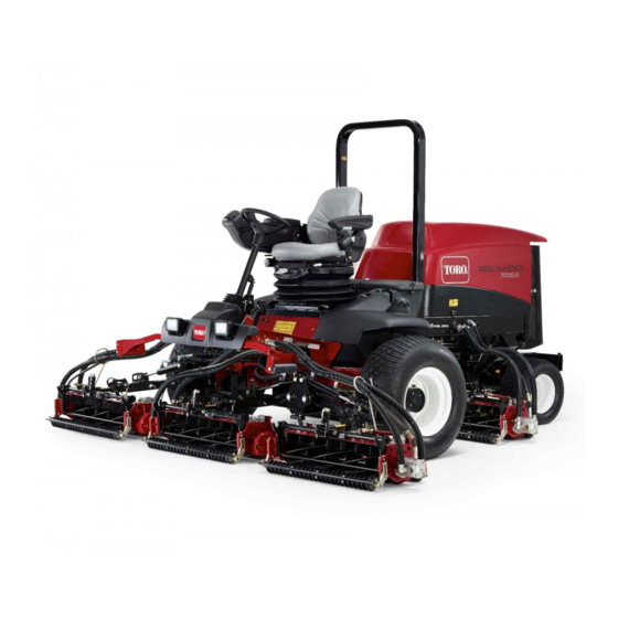
- Page 1 Form No. 3450-972 Rev A Reelmaster ® 7000-D 4-Wheel Drive Traction Unit Model No. 03780—Serial No. 410400000 and Up *3450-972* Register at www.Toro.com. Original Instructions (EN)
- Page 2 It is a violation of California Public Resource Code additional information, contact an Authorized Service Section 4442 or 4443 to use or operate the engine on Dealer or Toro Customer Service and have the model any forest-covered, brush-covered, or grass-covered and serial numbers of your product ready.
-
Page 3: Table Of Contents
Contents Lowering the Seat..........61 Locating the Jacking Points ......61 Lubrication ............62 Safety ............... 4 Greasing the Bearings and Bushings ....62 General Safety ........... 4 Engine Maintenance ........... 63 Safety and Instructional Decals ......5 Engine Safety ........... 63 Setup ...............11 Checking the Air Filter........ -
Page 4: Safety
Safety Belt Maintenance ..........84 Servicing the Alternator Belt ......84 Hydraulic System Maintenance ......85 This machine has been designed in accordance Hydraulic System Safety........85 with EN ISO 5395 (when you complete the setup Checking the Hydraulic Lines and procedures) and ANSI B71.4-2017. -
Page 5: Safety And Instructional Decals
Safety and Instructional Decals Safety decals and instructions are easily visible to the operator and are located near any area of potential danger. Replace any decal that is damaged or missing. decalbatterysymbols Battery Symbols decal100-6574 100-6574 Some or all of these symbols are on your battery. 1. - Page 6 decal110-9642 110-9642 1. Stored energy hazard—read the Operator's Manual. 2. Move the cotter pin to the hole closest to the rod bracket and then remove the lift arm and pivot yoke. decal120-1670 120-1670 1. Traction unit speed 3. Fast 2. Slow decal117-4763 117-4763 1.
- Page 7 decal121-3887 121–3887 1. Read the Operator’s Manual. decal133-8062 133-8062 decal125-8754 125–8754 1. Headlights 6. Slow 2. Engage 7. Lower the cutting units 3. Power take-off (PTO) 8. Raise the cutting units 4. Disengage 9. Read the Operator’s Manual. 5. Fast decal145-5258 145-5258 1.
- Page 8 decal136-3712 136-3712 1. Radiator screen 8. Planetary drive 15. Battery 22. Filter interval (hours) 2. Tire pressure 9. Check every 8 hours. 16. Diesel fuel 23. Hydraulic breather 3. Rear axle 10. Read the Operator’s 17. Brake functions 24. Safety air filter Manual for lubrication information.
- Page 9 CE Compliant Machines decal120-1683 120-1683 1. Warning—read the Operator's Manual; all operators should 4. Warning—do not park the machine on slopes; engage the be trained before operating the machine. parking brake, lower the cutting units, shut off the engine, and remove the key before leaving the machine.
- Page 10 decal138-1186 138-1186 Note: This machine complies with the industry standard stability test in the static lateral and longitudinal tests with the maximum recommended slope indicated on the decal. Review the instructions for operating the machine on slopes in the Operator’s Manual as well as the conditions in which you would operate the machine to determine whether you can operate the machine in the conditions on that day and at that site.
-
Page 11: Setup
Setup Loose Parts Use the chart below to verify that all parts have been shipped. Procedure Description Qty. Adjust the front cutting unit roller – No parts required position. Front hose guide (right) Install the cutting units. Front hose guide (left) –... -
Page 12: Installing The Cutting Units
Installing the Cutting Units Parts needed for this procedure: Front hose guide (right) Front hose guide (left) Preparing the Machine g019541 Remove the reel motors from the shipping Figure 3 brackets. 1. Roller support 3. Lower holes—32-inch Remove and discard the shipping brackets. cutting units 2. - Page 13 Positioning the Turf Compensating Spring and Installing the Hose Guide Cutting Units 4 g375690 Figure 7 1. Carriage bolt (3/8 x 1-1/4 3. Flange locknut (3/8 inch) g375671 inches) Figure 5 2. Turf-compensator bracket 1. Cutting unit 1 5. Cutting unit 5 2.
- Page 14 Installing the Hose Guide Cutting Units 5 g375672 Figure 11 g375694 Figure 9 1. Cutting unit 1 5. Cutting unit 5 1. Flange locknut (3/8 inch) 3. Capscrew 6. Reel motor 2. Cutting unit 2 2. Right tab (Carrier frame) 7.
- Page 15 Positioning the Turf Compensating Spring Cutting Unit 2 g379514 g375690 Figure 15 Figure 13 1. Cutting unit 1 5. Cutting unit 5 1. Carriage bolt (3/8 x 1-1/4 3. Flange locknut (3/8 inch) 6. Reel motor 2. Cutting unit 2 inches) 7.
- Page 16 g375690 Figure 17 g375694 Figure 19 1. Carriage bolt (3/8 x 1-1/4 3. Flange locknut (3/8 inch) 1. Flange locknut (3/8 inch) 3. Capscrew inches) 2. Right tab (Carrier frame) 2. Turf-compensator bracket Align the holes in the turf-compensator bracket Remove the flange locknut (3/8 inch) that with the holes in the cutting-unit frame (Figure...
- Page 17 Installing the Kickstand Increasing the Rear Cutting Unit Pivot Angle For each cutting unit, secure the kickstand to the chain bracket with the snapper pin (Figure 21). Increase the pivot angle of the rear cutting units by removing the 2 spacers, 2 hex-socket screws, and 2 flange locknuts (Figure 22 Figure...
- Page 18 Preparing to Install the Cutting Insert the shaft of the carrier frame into the pivot yoke of the lift arm. Units Secure the carrier-frame shaft to the pivot yoke Ensure that the countersunk thrust washer is with the lynch pin. inserted over the carrier-frame shaft (Figure 24).
- Page 19 g368648 Figure 28 3. Thrust washer 1. Lift arm (rear cutting unit) 4. Lynch pin 2. Lift-arm pivot shaft g368687 Figure 30 Insert the lift-arm yoke onto the carrier frame 1. Lift arm (rear cutting unit) 3. Thrust washer shaft (Figure 29).
-
Page 20: Preparing The Machine
Installing the Reel Motors Coat the spline shaft of the reel motor with clean grease. Oil the reel motor O-ring and install it onto the Preparing the Machine motor flange. Install the motor by rotating it clockwise so that the motor flanges clear the bolts (Figure 32). -
Page 21: Installing The Hood Lock For Ce
Installing the Hood Lock for CE Compliance Parts needed for this procedure: Hood-lock bracket Rivet g012628 Screw (1/4 x 2 inch) Figure 34 Flat washer (1/4 inch) 1. Hood-latch bracket 2. Rivets Locknut (1/4 inch) Remove the hood-latch bracket from the hood. Procedure While aligning the mounting holes, position the CE lock bracket and the hood-latch bracket onto... -
Page 22: Applying The Ce Decals
Applying the CE Decals Parts needed for this procedure: CE decal Production year decal g354465 Figure 36 Warning decal 1. Hood latch Procedure Screw the bolt into the other arm of hood-lock bracket to lock the latch in position (Figure 37). -
Page 23: Product Overview
Product Overview CE Decal Location Table (cont'd.) CE warning decal—over the standard warning decal. g320359 Figure 41 1. Front cutting units 4. Operator's seat 2. Control arm 5. Engine hood 3. Steering wheel 6. Rear cutting unit g371043 Controls Figure 40 1. - Page 24 Parking-Brake Pedal Mow-Speed Limiter To engage the parking brake, (Figure 42) connect the When the mow-speed limiter (Figure 43) is rotated pedals together with the pedal-locking latch, push forward, it allows the cutting units to engage and limits down on the right brake pedal while engaging the toe the maximum ground speed during mowing.
- Page 25 Engine-Speed Switch The engine-speed switch (Figure 44) has 2 modes to change the engine speed. By momentarily tapping the switch, you can increase or decrease the engine speed in 100 rpm increments. Press and hold the switch to move the engine speed directly to high or low idle, depending on which end of the switch you press.
- Page 26 • Manual Fan Reversal—activated by pressing the InfoCenter Icon Description (cont'd.) left and right buttons simultaneously. • Beeper—activated when lowering the decks or for advisories and faults. Coolant temperature—indicates the engine coolant temperature in either Note: The purpose of each button may change °C or °F depending on what is required at the time.
- Page 27 PTO have been on, as well NOx control diagnosis malfunction; as the number of hours the drive the machine back to the shop machine has been transported and contact your authorized Toro and service due distributor (software version F and later). Counts...
- Page 28 If you changed the PIN code and forgot the code, PIN code to access protected menus contact your authorized Toro distributor for assistance. Controls the amount of time Auto Idle From the M , use the center button to...
- Page 29 Setting the Front and Rear Reel Press the middle button to enter the PIN code (Figure 49D). Speeds Wait until the red indicator light of the InfoCenter Although the front and rear reel speeds are calculated illuminates. by inputting the number of blades, mow speed and Note: If the InfoCenter accepts the PIN code HOC into the InfoCenter, you can manually change the...
-
Page 30: Specifications
To ensure optimum performance and continued safety functioning properly on the machine. certification of the machine, use only genuine Toro replacement parts and accessories. Replacement • Before mowing, always inspect the machine to... -
Page 31: Filling The Fuel Tank
• Do not use fuel additives. after converting to biodiesel blends. Petroleum Diesel • Contact your authorized Toro distributor if you wish for more information on biodiesel. Cetane rating: 45 or higher Sulfur content: Ultra-low sulfur (<15 ppm) Adding Fuel... -
Page 32: Performing Daily Maintenance
Important: If your machine fails any of the interlock switch checks, contact your authorized Toro distributor. Preparing the Machine Drive the machine slowly to an open area. Lower the cutting units, shut off the engine, and engage the parking brake. -
Page 33: Adjusting The Seat
Adjusting the Seat During Operation During Operation Safety General Safety • The owner/operator can prevent and is responsible for accidents that may cause personal injury or property damage. • Wear appropriate clothing, including eye protection; long pants; substantial, slip-resistant footwear; and hearing protection. Tie back long hair and do not wear loose clothing or loose jewelry. - Page 34 – Allow the machine to cool before adjusting, determine whether you can operate the machine servicing, cleaning, or storing it. in the conditions on that day and at that site. Changes in the terrain can result in a change in •...
-
Page 35: Fuel Gauge
Fuel Gauge Starting the Engine Important: Bleed the fuel system if any of the Use the fuel gauge (Figure 52) at the top of the tank following situations have occurred: to determine the fuel level. • The engine has shut off because the machine ran out of fuel. -
Page 36: Locking The Cutting-Unit Pivot
Wait for all moving parts to stop. Locking the Cutting-Unit Pivot Cutting Grass on a Hill Side Lock the cutting-unit pivots to prevent the cutting units g370798 Figure 55 from rotating downhill when cutting across the face of a hill. 1. -
Page 37: Driving The Machine In Transport Mode
Driving the Machine in Adjusting the Transport Mode Turf-Compensation Spring Press the PTO switch to the D position ISENGAGE The turf-compensation spring (Figure 59) transfers (Figure 57). the weight from the front roller to the rear roller. This helps to reduce a wave pattern in the turf, also known as marcelling or bobbing. -
Page 38: Adjusting The Cutting-Unit Counterbalance
Adjusting the Cutting-Unit Counterbalance Rear Cutting Units CAUTION The springs are under tension and could cause personal injury. Use caution when adjusting the springs. You can adjust the amount of counterbalance force applied to the rear cutting-units to help compensate for different turf conditions, and to maintain a uniform height of cut in rough conditions or in areas of thatch buildup. -
Page 39: Adjusting The Cutting Unit-Turnaround Height
Adjusting the Cutting WARNING Unit-Turnaround Height The machine does not have a rollover protection system (ROPS) when the roll bar is The lift-arm switch (Figure 48) is located behind the folded down and should not be considered right, front lift arm (cutting unit #5). a ROPS. -
Page 40: Raising The Rollbar
g368910 Figure 62 1. Lynch pin 3. Roll-bar pin 2. Upper holes (pivot 4. Roll-bar and lynch pins g368924 brackets) (lower holes—pivot Figure 63 brackets) 1. Roll-bar pin 3. Upper holes (pivot brackets) Support the weight of the upper roll-bar tube 2. - Page 41 Important: the back pressure is too high, soot is not incinerating Minimize the amount of time that you in the soot filter through normal engine operation. To idle the engine or operate the engine at low-engine keep the DPF clear of soot, remember the following: speed to help reduce the accumulation of soot in the soot filter.
- Page 42 DPF Ash Accumulation • When enough ash accumulates, the engine computer sends information to the InfoCenter • The lighter ash is discharged through the exhaust in the form of an engine fault to indicate the system; the heavier ash collects in the soot filter. accumulation of ash in the DPF.
- Page 43 Types of Diesel Particulate Filter Regeneration Types of diesel particulate filter regeneration that are performed while the machine is operating: Type of Regeneration Conditions that cause DPF regeneration DPF description of operation Passive Occurs during normal operation of the machine at •...
- Page 44 Types of diesel particulate filter regeneration that require you to park the machine: (cont'd.) Type of Regeneration Conditions that cause DPF regeneration DPF description of operation Recovery Occurs because the operator ignored requests for • When the reset-standby/parked or recovery a parked regeneration and continued operating the machine, adding more soot to the DPF regeneration icon...
- Page 45 press the right button to select the Technician entry DPF Operation Table (cont'd.) (Figure 71). State Description Reset Regen The engine computer is running a reset regeneration. The engine computer is requesting that Parked Stby you run a parked regeneration. Parked Regen You initiated a parked regeneration request and the engine computer is...
- Page 46 Assist DPF Regeneration • The icon displays in the InfoCenter while the reset regeneration is processing. • The engine computer adjusts engine settings to • Whenever possible, do not shut off the engine or raise the exhaust temperature. reduce engine speed while the reset regeneration •...
- Page 47 g227304 g224394 Figure 76 Figure 78 Press the right button to change the inhibit Note: If the engine exhaust temperature is too low, regeneration setting from On to Off (Figure the InfoCenter displays A #186 (Figure 79) to DVISORY or from Off to On (Figure 77).
- Page 48 Parked or Recovery Regeneration regeneration required—power takeoff disabled #189 (Figure 83). DVISORY • When the engine computer requests either a parked regeneration or a recovery regeneration, the regeneration request icon (Figure 80) displays in the InfoCenter. g224398 Figure 83 Important: Perform a parked regeneration to restore the PTO function;...
- Page 49 Important: Perform a recovery regeneration Move the machine outside to an area away from to restore the PTO function; refer to Preparing combustible materials. to Perform a Parked or Recovery Regeneration Park the machine on a level surface. (page 49) Performing a Parked or Recovery Regeneration (page 49).
- Page 50 At the DPF checklist screen, verify that the parking brake is engaged and that the engine speed is set to low idle (Figure 91). g224402 g224407 g224629 Figure 89 At the V screen, verify that you g227679 ERIFY FUEL LEVEL Figure 91 have 1/4 tank of fuel if you are performing the parked regeneration or 1/2 tank of fuel if you are...
- Page 51 The InfoCenter displays the I NITIATING Check Message and Corrective Action Table message (Figure 93). EGEN (cont'd.) g224411 Corrective Action: Start and run the engine. g227681 Figure 93 Corrective Action: Run the engine to warm the coolant The InfoCenter displays the time to complete temperature to 60°C (140°F).
- Page 52 Canceling a Parked or Recovery Regeneration displays A #183 (Figure 96). Press the DVISORY left button to exit to the home screen. Use the Parked Regen Cancel or Recovery Regen Cancel setting to cancel a running parked or recovery regeneration process. Access the DPF Regeneration menu (Figure 98).
-
Page 53: Operating Tips
Operating Tips Identifying the Tie-Down Points Becoming Familiar with the The tie-down points are in the following locations: Machine • On each side of the frame under the front steps Before mowing grass, practice operating the machine • The rear bumper in an open area. - Page 54 Install the Reverse Tow Kit Required Parts (purchased separately): Reverse Preparing the Machine for Tow Kit, Toro Part No. 136-3620 Operation Important: If you need to push or tow the machine in reverse, you must first bypass the Remove the Reverse Tow Kit check valve in the 4-wheel-drive manifold.
- Page 55 Pushing or Towing the Machine Forward Only If you need to push or tow the machine forward only, you can just rotate the bypass valve. Important: If you need to push or tow the machine in reverse, refer to Preparing the Machine to Push or Tow in Reverse (page 54).
-
Page 56: Maintenance
• – Shut off the engine and remove the key. To ensure safe, optimal performance of the machine, use only genuine Toro replacement – Wait for all movement to stop. parts. Replacement parts made by other – Allow the machine to cool before adjusting, manufacturers could be dangerous, and such use servicing, cleaning, or storing it. - Page 57 Maintenance Service Maintenance Procedure Interval • Change the air filter. Service the air filter earlier if the service indicator shows red. Service it more frequently in extremely dirty or dusty conditions. • Check the fuel lines and connections for deterioration, damage, or loose connections. •...
-
Page 58: Daily Maintenance Checklist
Daily Maintenance Checklist Duplicate this page for routine use. Maintenance For the week of: Check Item Mon. Tues. Wed. Thurs. Fri. Sat. Sun. Check the safety interlock operation. Check the brake operation. Check the levels of the engine oil and fuel. Check the cooling-system fluid level. -
Page 59: Pre-Maintenance Procedures
Notation for Areas of Concern Inspection performed by: Item Date Information Pre-Maintenance Procedures Preparing for Maintenance Park the machine on a level surface, lower the cutting units, and engage the parking brake. Shut off the engine, remove the key, and wait for all moving parts to stop. -
Page 60: Closing The Hood
Closing the Hood Carefully rotate the hood closed (Figure 105). g369006 Figure 106 1. Battery-compartment 2. Latch (rubber) cover Rotate the cover up. Tilting the Seat g369219 Figure 105 Move the seat latch outward (Figure 107). 1. Hood latch (2) Secure the hood with the 2 hood latches. -
Page 61: Lowering The Seat
g369008 Figure 108 1. Slot (seat support) 2. Prop rod Lowering the Seat g369205 Rotate the seat slightly, and lift the prop rod out Figure 110 of the dent of the seat support slot (Figure 109). • Rear of the machine—at the center of the axle (Figure 111) Note:... -
Page 62: Lubrication
Lubrication • Steering cylinder ball joints (2), refer to Figure 114 Greasing the Bearings and Bushings Service Interval: Every 50 hours Grease the bearings and bushings immediately after washing the machine. Grease Specification: No. 2 lithium grease Prepare the machine for maintenance; refer to Preparing for Maintenance (page 59). -
Page 63: Engine Maintenance
Engine Maintenance • Lift arm pivot bushings (1 per cutting unit), refer to Figure 116 • Cutting unit carrier frame (2 per cutting unit), Engine Safety refer to Figure 116 • Cutting unit lift arm pivot (1 per cutting unit), •... -
Page 64: Changing The Air Filter
g369207 g369203 Figure 118 Figure 119 1. Latch (air-cleaner cover) Close and latch the hood; refer to Closing the Hood (page 60). Remove the cover from the air-cleaner housing. Before removing the filter, use low-pressure Changing the Air Filter air—275 kPa (40 psi), clean and dry—to help remove large accumulations of debris packed between outside of primary filter and Service Interval: Every 400 hours Service the air filter... -
Page 65: Oil Specification
Alternate oil: SAE 10W-30 or 5W-30 (all and the body of the air filter. temperatures) Important: Do not use a damaged filter Toro Premium Engine Oil is available from your element. authorized Toro distributor in either 15W-40 or 10W-30 viscosity grades. Assemble the primary-filter element. Apply... -
Page 66: Crankcase Oil Capacity
g369817 Figure 124 1. Oil filler port 2. Oil-fill cap Install the oil-fill cap and dipstick. Close and latch the hood; refer to Closing the g369816 Figure 123 Hood (page 60). 1. Dipstick 3. Full oil-level mark Crankcase Oil Capacity 2. -
Page 67: Servicing The Diesel-Oxidation Catalyst (Doc) And The Soot Filter
Refer to the Engine section in the Service Manual for information on disassembling and assembling the diesel-oxidation catalyst and the soot filter of the DPF. g369728 Refer to your authorized Toro distributor for Figure 126 diesel-oxidation catalyst and the soot filter 1. Filter adapter 2. Oil filter replacement parts or service. -
Page 68: Fuel System Maintenance
Fuel System Maintenance DANGER Under certain conditions, fuel and fuel vapors are highly flammable and explosive. A fire or explosion from fuel can burn you and others and can cause property damage. • Fill the fuel tank outdoors, in an open area, when the engine is off and is cold. -
Page 69: Changing The Fuel-Water Separator Filter
Changing the Fuel-Water Changing the Engine-Fuel Separator Filter Filter Service Interval: Every 400 hours Service Interval: Every 400 hours Drain the fuel-water separator; refer to steps Prepare the machine for maintenance; refer to through Draining the Fuel-Water Separator Preparing for Maintenance (page 59). -
Page 70: Draining And Cleaning The Fuel Tank
Draining and Cleaning the Fuel Tank Service Interval: Every 800 hours Before storage Drain and clean the fuel tank if the fuel system becomes contaminated or if the machine is to be stored for an extended period. Use clean fuel to flush out the tank. -
Page 71: Electrical System Maintenance
• Fill the battery where clean water is always Apply a coat of Grafo 112X (skin-over) grease, available for flushing the skin. Toro Part No. 505-47 to the battery posts and battery-cable clamps. Prepare the machine for maintenance; refer to Preparing for Maintenance (page 59). -
Page 72: Servicing The Battery
Servicing the Battery Service Interval: Every 50 hours Note: Keep the terminals and the entire battery case clean because a dirty battery will discharge slowly. Prepare the machine for maintenance; refer to Preparing for Maintenance (page 59). Open the battery-compartment cover; refer to Accessing the Battery Compartment (page 60). -
Page 73: Drive System Maintenance
100 ft-lb). Note: The front wheel nuts are 1/2–20 UNF; Repeat step for the other drive wheel. the rear wheel nuts are M12 x 1.6-6H (metric). If either wheel moves, contact your authorized Toro distributor to have the planetary drive rebuilt. -
Page 74: Checking The Planetary Gear-Drive Lubricant
Checking the Planetary If the oil level is low, remove the fill plug at the 12 o’clock position and add oil until it begins to Gear-Drive Lubricant flow out of the hole at the 3 o’clock position. Check the O-ring for the plug(s) for wear or Service Interval: Every 400 hours (check if you damage. -
Page 75: Checking The Oil Level Of The Rear Axle
Place a drain pan under the planetary hub, remove the drain plug at the 6 o’clock position, and allow the oil to fully drain (Figure 139). Check the O-rings for the fill, check, and drain plugs for wear or damage. Note: Replace the O-ring(s) as needed. -
Page 76: Changing The Oil In The Rear Axle
Remove each drain plug (Figure 144) and allow the oil to drain into a drain pan. Remove the 2 axle housing check plugs and the fill plug to ease in draining of the oil (Figure 145). g009716 Figure 143 1. Check plug (axle housing) 2. -
Page 77: Mow Speed-Spacer Table
Check the gear-case oil level. Note: The gear-oil level is correct if the oil level is at the bottom of the check/fill-plug hole. If the gear-oil level is low, add enough of the specified case oil to bring the level up to the bottom of the check/fill-plug hole. - Page 78 In the S , press the middle button ETTING until the P option is highlighted, ROTECTED ENUS and press the right button. In the P screen, enter the PIN ROTECTED ENUS code; refer to Accessing Protected Menus (page 28). In the S menu, press the middle button ETTINGS until the M...
-
Page 79: Adjusting The Traction Drive For Neutral
Adjusting the Traction Drive for Neutral The machine must not move forward or backward when you release the traction pedal. If the machine moves, adjust the traction drive for neutral. Park the machine on a level surface, shut off the engine, position the speed control into the low range, and lower the cutting units. -
Page 80: Adjusting The Rear-Wheel Toe-In
Tighten the clamp at the connected end of the tie rod. Assemble the tie-rod end to the axle case-steering arm with the slotted nut. Measure the toe-in; refer to Checking the Rear-Wheel Alignment (page 79). If needed, remove the slotted nut and repeat steps through 9. -
Page 81: Cooling System Maintenance
Cooling System • Preferred option: If distilled water is not available, use a pre-mix coolant instead of a concentrate. Maintenance • Minimum requirement: If distilled water and pre-mix coolant are not available, mix concentrated coolant with clean drinkable water. Cooling System Safety Checking the Coolant Level •... -
Page 82: Servicing The Engine Cooling System
Note: The coolant level is correct if it is to the toward the back. Then clean from the back mark of the expansion tank. side and blow toward the front. Repeat the procedure several times until all chaff and debris If the coolant is low, add the specified coolant is removed. -
Page 83: Brake Maintenance
Brake Maintenance Adjusting the Service Brakes Adjust the service brakes when there is more than 13 mm (1/2 inch) of free travel of the brake pedal, or if the brakes slip. Free travel is the distance the brake pedal moves before you feel braking-pedal resistance. Prepare the machine for maintenance;... -
Page 84: Belt Maintenance
Belt Maintenance Servicing the Alternator Belt Service Interval: Every 100 hours Check the condition and tension of the belts (Figure 161) after every 100 operating hours. Park the machine on a level surface, lower the cutting units, engage the parking brake, shut off the engine, and remove the key. -
Page 85: Hydraulic System Maintenance
Service Interval: Before each use or daily This fluid is compatible with the elastomers used in Toro hydraulic systems and is suitable for a Check the hydraulic lines and hoses for leaks, kinked wide-range of temperature conditions. This fluid is... -
Page 86: Replacing The Hydraulic Filters
Use the following Toro hydraulic filters: (cont'd.) 75-1310 Under the seat Charge filter plate. Important: Using another type of filter may void the warranty on some components. Replacing the Charge Filter Prepare the machine for maintenance; refer to Preparing for Maintenance (page 59). -
Page 87: Hydraulic Fluid Capacity
If the fluid becomes contaminated, contact your local 1. Return-filter head 2. Return filter authorized Toro distributor, because the system must be flushed. Contaminated fluid looks milky or black when compared to clean fluid. Align a drain pan under the return filter, and remove the filter. -
Page 88: Cutting Unit Maintenance
Check for hydraulic leaks, shut off the engine, and remove the key. Note: Additional instructions and procedures on backlapping are available in the Toro Sharpening Reel Repair all hydraulic leaks. and Rotary Mowers Manual, Form No. 80-300SL. Close and latch the hood; refer to... - Page 89 Rotate the lever for the mow-speed limiter forward to the M position (Figure 169). g370552 Figure 167 g370644 Figure 169 1. Mow-speed limiter 3. Lower mow/raise control lever 2. PTO switch Press the PTO switch to the E position. NGAGE Move the lower mow/raise control lever forward.
-
Page 90: Extended Maintenance
Finishing Backlapping Extended Maintenance Important: If you do not return the backlap switch to the O position after backlapping, the cutting Chassis and Engine units will not raise or function properly. Shut off the engine and remove the key. Service Interval: Every 2 years—Replace the hydraulic hoses. -
Page 91: Cleaning
Clean the battery, terminals, and posts with a wire brush and baking-soda solution. Coat the cable terminals and battery posts with Grafo 112X skin-over grease (Toro Part No. 505-47) or petroleum jelly to prevent corrosion. Slowly charge the battery every 60 days for 24 hours to prevent lead sulfation of the battery. -
Page 92: Preparing The Engine
Preparing the Engine Drain the engine oil from the oil pan and install the drain plug. Remove and discard the oil filter. Install a new oil filter. Fill the engine with specified motor oil. Start the engine and run it at idle speed for approximately 2 minutes. - Page 93 Notes:...
- Page 94 The Toro Company (“Toro”) respects your privacy. When you purchase our products, we may collect certain personal information about you, either directly from you or through your local Toro company or dealer. Toro uses this information to fulfil contractual obligations - such as to register your warranty, process your warranty claim or to contact you in the event of a product recall - and for legitimate business purposes - such as to gauge customer satisfaction, improve our products or provide you with product information which may be of interest.
- Page 95 While the exposure from Toro products may be negligible or well within the “no significant risk” range, out of an abundance of caution, Toro has elected to provide the Prop 65 warnings. Moreover, if Toro does not provide these warnings, it could be sued by the State of California or by private parties seeking to enforce Prop 65 and subject to substantial penalties.
- Page 96 Countries Other than the United States or Canada Customers who have purchased Toro products exported from the United States or Canada should contact their Toro Distributor (Dealer) to obtain guarantee policies for your country, province, or state. If for any reason you are dissatisfied with your Distributor's service or have difficulty obtaining guarantee information, contact your Authorized Toro Service Center.