Toro 03781 Operator's Manual
4-wheel drive traction unit
Hide thumbs
Also See for 03781:
- Operator's manual (64 pages) ,
- Service manual (468 pages) ,
- Operator's manual (120 pages)

Related Manuals for Toro 03781


Summary of Contents for Toro 03781
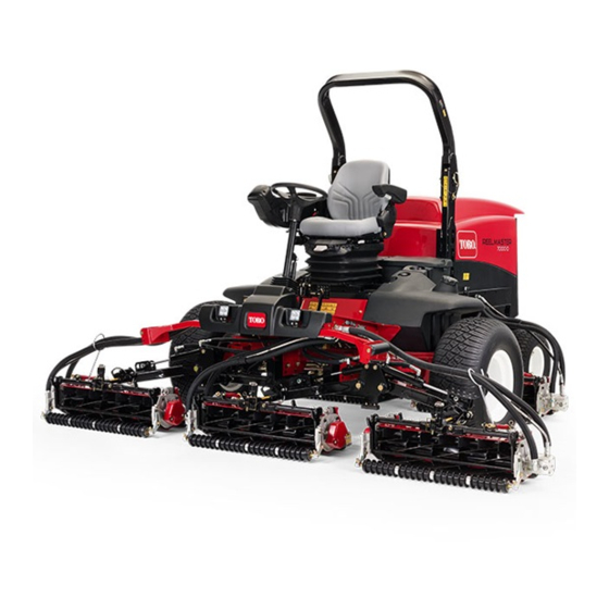
- Page 1 Form No. 3386-653 Rev A Reelmaster ® 7000-D 4-Wheel Drive Traction Unit Model No. 03781—Serial No. 315000001 and Up *3386-653* A Register at www.Toro.com. Original Instructions (EN)
- Page 2 This product complies with all relevant European directives, You may contact Toro directly at www.Toro.com for product for details please see the separate product specific Declaration and accessory information, help finding a dealer, or to register of Conformity (DOC) sheet.
-
Page 3: Table Of Contents
Safety ................4 Fuses ..............45 Safe Operating Practices........... 4 Drive System Maintenance .........46 Toro Riding Mower Safety ........6 Checking the Torque of the Wheel Nuts.....46 Sound Power Level ..........7 Checking the Planetary Drive Gear/Brake Sound Pressure Level..........7 Oil ..............46... -
Page 4: Safety
Safety protection. Long hair, loose clothing, or jewelry may get tangled in moving parts. Do not operate the equipment when barefoot or wearing open sandals. This machine meets or exceeds EN ISO 5395:2013 • Thoroughly inspect the area where the equipment is to (when appropriate decals applied), and ANSI B71.4-2012 be used and remove all objects which may be thrown by specifications in effect at the time of production. - Page 5 • • Remember there is no such thing as a safe slope. Travel Slow down and use caution when making turns and on grass slopes requires particular care. To guard against crossing roads and sidewalks. Stop cylinders/reels if not overturning: mowing.
-
Page 6: Toro Riding Mower Safety
Engage traction drive slowly, always keep foot on traction Toro Riding Mower Safety pedal, especially when traveling downhill. The following list contains safety information specific to Toro Use reverse on traction pedal for braking. products or other safety information that you must know that •... -
Page 7: Sound Power Level
Sound Power Level Vibration Level This unit has a guaranteed sound power level of 101 dBA, Hand-Arm which includes an Uncertainty Value (K) of 1 dBA. Measured vibration level for right hand =0.3 m/s Sound power level was determined according to the Measured vibration level for left hand =0.3 m/s procedures outlined in ISO 11094. - Page 8 117–2718 106-6755 1. Engine coolant under 3. Warning—do not touch the pressure. hot surface. 2. Explosion hazard—read 4. Warning—read the the Operator's Manual. Operator's Manual. 121–5644 1. Light switch 6. Slow 98-4387 2. Engage 7. Lower 3. Power take-off 8. Raise 1.
- Page 9 121–3884 1. Engine—stop 3. Engine—start 2. Engine—preheat 125–4605 112-5019 1. Power seat, 10A 6. Power supplied, 10A Work light, 10A 7. Controller, 2A 3. Engine, 10A 8. Power supplied, 7.5A 4. Cigarette lighter, 10A 9. Controller, 2A 10. Engine preheat, 60A 5.
- Page 10 Battery Symbols Some or all of these symbols are on your battery 1. Explosion hazard 6. Keep bystanders a safe distance from the battery. 2. No fire, open flame, or 7. Wear eye protection; smoking. explosive gases can cause blindness and other injuries 8.
- Page 11 120-1683 1. Warning—read the Operator's Manual, do not operate this 4. Warning—do not park the machine on slopes; engage the machine unless you are trained. parking brake, lower the cutting units, stop the engine and remove the ignition key before leaving the machine. 2.
- Page 12 120-1686 Affix over part no. 120–1683 for CE* *This safety decal includes a slope warning required on the machine fro compliance to the European Lawn Mower Standard EN ISO 5395:2013. The conservative maximum slope angles indicated for operation of this machine are prescribed by and required by this standard. 1.
-
Page 13: Setup
Setup Loose Parts Use the chart below to verify that all parts have been shipped. Procedure Description Qty. – No parts required Adjust the support rollers Used only on machines requiring CE Warning decal Compliance. Hood lock bracket Rivet Used only on machines requiring Screw, 1/4 x 2 inch European CE Compliance. -
Page 14: Adjusting The Support Rollers
Adjusting the Support Rollers Replacing the Warning Decal for CE Compliance No Parts Required Parts needed for this procedure: Procedure Warning decal Depending on what width cutting units are to be installed on the traction, adjust the support rollers as follows: Procedure •... - Page 15 G012629 Figure 6 1. CE lock bracket 2. Bolt and nut assembly 4. Align the washers with the holes on the inside of the Figure 4 hood. 1. Hood latch 5. Rivet the brackets and the washers to the hood (Figure 2.
-
Page 16: Installing The Cutting Units
Installing the Cutting Units Parts needed for this procedure: Figure 10 1. Turf compensation spring 3. Spring tube Front hose guide-R.H. 2. Rod bracket Front hose guide-L.H. B. Remove the flange nut securing the spring tube Procedure bolt to the carrier frame tab (Figure 10) Remove the assembly. - Page 17 Figure 13 1. Hose guide (Left hand 3. Nuts shown) 2. Rod bracket g019602 Figure 14 1. Hose guides (each must lean toward the center cutting unit) Note: When installing or removing the cutting units, make sure the hairpin cotter is installed in the spring rod hole next to the rod bracket.
- Page 18 9. For the front cutting units, slide a cutting unit under the lift arm while inserting the carrier frame shaft up into the lift arm pivot yoke (Figure 16). Make sure the thrust washer is in position on the carrier frame shaft. 10.
-
Page 19: Adjusting The Turf Compensation Spring
Adjusting the Turf Compensation Spring No Parts Required Figure 19 Procedure 1. Lift arm chain 3. Snapper pin The turf compensation spring (Figure 21) transfers weight 2. Chain bracket from the front to the rear roller. (This helps to reduce a wave pattern in the turf, also known as marcelling or bobbing.) 14. -
Page 20: Using The Cutting Unit Kickstand
Using the Cutting Unit Kickstand Parts needed for this procedure: Cutting unit kickstand Procedure Whenever the cutting unit has to be tipped to expose the bedknife/reel, prop up the rear of the cutting unit with the kickstand to make sure the nuts on the back end of the bedbar adjusting screws are not resting on the work surface Figure 23 (Figure 22). -
Page 21: Checking Fluid Levels
Checking Fluid Levels No Parts Required Procedure 1. Check the rear axle lubricant level before the engine is first started, refer to Checking the Rear Axle Lubricant in Drive System Maintenance. 2. Check the hydraulic fluid level before the engine is first started, refer to Checking the Hydraulic Fluid Level in Figure 24 Operation. -
Page 22: Product Overview
Mow Speed Limiter Product Overview When the mow speed limiter (Figure 26) is flipped up it will control the mow speed and allow the cutting units to be Controls engaged. Each spacer adjusts the mowing speed by ½ mile per hour. The more spacers you have, on the top of the bolt Brake Pedals the slower you will go. - Page 23 Bag Holder unit blades. Push in the button to disengage the cutting unit blades. Use the bag holder (Figure 28) for storage. Backlap Levers Use the backlap levers for backlapping the reels (Figure 29). Figure 27 1. Lower mow/raise control 4.
- Page 24 Seat Adjustments Using the InfoCenter LCD Display The InfoCenter LCD display shows information about your Fore and Aft Adjusting Lever machine such as the operating status, various diagnostics and other information about the machine (Figure 31) There Pull out on the lever to slide the seat fore or aft (Figure 30). is a splash screen and main information screen of the InfoCenter.
- Page 25 InfoCenter Icon Description InfoCenter Icon Description (cont'd.) SERVICE DUE Indicates when scheduled service should be performed Indicates when the cutting units are Info icon being lowered Indicates when the cutting units are Hour Meter being raised PIN passcode Fast Hydraulic Oil Temperature-indicates the hydraulic oil temperature Slow CAN bus...
- Page 26 InfoCenter. The menu choices faults. Refer to the Service are English or Metric Manual or your Authorized Toro Distributor for more Language Controls the language used information on the Faults on the InfoCenter*. menu and the information contained there.
- Page 27 To Set the Mow Speed Machine Controller Revision Lists the software revision of the master controller. • In the Settings Menu, scroll down to Mow Speed. InfoCenter Revision Lists the software revision of • Press the right button to select mow speed. the InfoCenter.
-
Page 28: Specifications
A selection of Toro approved attachments and accessories is available for use with the machine to enhance and expand its capabilities. Contact your Authorized Service Dealer or Distributor or go to www.Toro.com for a list of all approved attachments and accessories. -
Page 29: Operation
• Alternate oil: SAE 10W-30 or 5W-30 (all temperatures) 1. Dipstick Note: Toro Premium Engine oil is available from your distributor in either 15W-40 or 10W-30 viscosity. See the parts catalog for part numbers. 4. If the oil is below the safe range, remove the fill cap... -
Page 30: Checking The Cooling System
Figure 34 1. Oil-fill cap Note: When using different oil, drain all old oil from the crankcase before adding new oil. Figure 35 5. Install the oil fill cap and dipstick. 1. Expansion tank 6. Close the hood and secure it with the latches. 2. - Page 31 WARNING DANGER Fuel is harmful or fatal if swallowed. Long-term In certain conditions during fueling, static exposure to vapors can cause serious injury and electricity can be released causing a spark which illness. can ignite the fuel vapors. A fire or explosion from fuel can burn you and others and can damage •...
-
Page 32: Checking The Hydraulic Fluid Level
Toro Premium All Season Hydraulic Fluid (Available in 5 gallon pails or 55 gallon drums. See parts catalog or Toro distributor for part numbers.) Alternate fluids: If the Toro fluid is not available, other fluids may be used provided they meet all the following material properties and industry specifications. -
Page 33: Checking The Interlock Switches
Checking the Interlock 1. Remove your foot from the traction pedal and ensure that it is in neutral. Ensure that the parking brake is set. Switches 2. Move the throttle control to the low idle position. Service Interval: Before each use or daily 3. -
Page 34: Adjusting The Lift Arm Turn Around Position
springs can be positioned on the back side of the spring actuator to remove all counter balance (forth position). 1. Position the machine on a level surface, lower the cutting units, stop the engine, engage the parking brakes, and remove the key from ignition switch. 2. -
Page 35: Jacking Points
may be torn accidentally. Another benefit of the brakes is to maintain traction. For example, in some slope conditions, the uphill wheel slips and loses traction. If this situation occurs, depress the uphill turn pedal gradually and intermittently until the uphill wheel stops slipping, thus, increasing traction on the downhill wheel. -
Page 36: Maintenance
Maintenance Note: Determine the left and right sides of the machine from the normal operating position. Recommended Maintenance Schedule(s) Maintenance Service Maintenance Procedure Interval • Torque the wheel nuts. After the first 8 hours • Change the engine oil and filter. After the first 50 hours •... -
Page 37: Daily Maintenance Checklist
Daily Maintenance Checklist Duplicate this page for routine use. Maintenance For the week of: Check Item Mon. Tues. Wed. Thurs. Fri. Sat. Sun. Check the safety interlock operation Check the brake operation Check the engine oil and fuel level Check the cooling system fluid level Drain the... -
Page 38: Service Interval Chart
Service Interval Chart Figure 41 CAUTION If you leave the key in the ignition switch, someone could accidently start the engine and seriously injure you or other bystanders. Remove the key from the ignition before you do any maintenance. -
Page 39: Premaintenance Procedures
Premaintenance Lubrication Procedures Greasing the Bearings and Bushings Removing the Hood Service Interval: Every 50 hours 1. Release hood latches (Figure 42) and pivot open the hood. The machine has grease fittings that must be lubricated regularly with No. 2 General Purpose Lithium Base Grease. If the machine is operated under normal conditions, lubricate all bearings and bushings after every 50 hours of operation or immediately after every washing. - Page 40 • Steering cylinder ball joints (2) (Figure 45) Figure 47 Figure 45 1. Top fitting on king pin • Tie rod ball joints (2) (Figure 45) • King pin bushings (2) (Figure 45). The top fitting on the king pin should only be lubricated annually (2 pumps).
-
Page 41: Engine Maintenance
Engine Maintenance This cleaning process prevents debris from migrating into the intake when the primary filter is removed. 3. Remove and replace the primary filter (Figure 50). Servicing the Air Cleaner Cleaning of the used element is not recommended due Service Interval: Every 400 hours to the possibility of damage to the filter media. -
Page 42: Servicing The Engine Oil And Filter
Servicing the Engine Oil and Adjusting the Throttle Filter Adjust the throttle cable (Figure 54) so that the governor lever on the engine contacts the high speed set bolt at the Service Interval: After the first 50 hours same point that the throttle cable contacts the end of the slot in the control arm. -
Page 43: Fuel System Maintenance
Servicing the Water Separator Fuel System Maintenance Service Interval: Before each use or daily—Drain water or other contaminants from fuel filter/water separator. DANGER Every 400 hours—Replace the fuel filter canister. Under certain conditions, diesel fuel and fuel Drain water or other contaminants from water separator daily. vapors are highly flammable and explosive. -
Page 44: Electrical System Maintenance
Electrical System DANGER Maintenance Battery electrolyte contains sulfuric acid which is a deadly poison and causes severe burns. Charging and Connecting the • Do not drink electrolyte and avoid contact Battery with skin, eyes or clothing. Wear safety glasses to shield your eyes and rubber gloves to protect your hands. -
Page 45: Battery Care
Rinse with clear water. Coat the battery posts and cable connectors with CALIFORNIA Grafo 112X (skin-over) grease (Toro Part No. 505-47) or Proposition 65 Warning petroleum jelly to prevent corrosion. Battery posts, terminals, and related... -
Page 46: Drive System Maintenance
Drive System Maintenance Checking the Torque of the Wheel Nuts Service Interval: After the first 8 hours Every 200 hours WARNING Failure to maintain proper torque of the wheel nuts could result in failure or loss of wheel and may result in personal injury. -
Page 47: Changing The Planetary Gear Drive Oil
5. Repeat steps 1–3 on the opposite planetary gear assembly. Changing the Planetary Gear Drive Oil Service Interval: After the first 250 hours Every 800 hours (Or yearly, whichever comes first) G024858 Change the oil initially after first 250 hours of operation. Figure 64 Thereafter, change the oil every 800 hours, or yearly, 1. -
Page 48: Changing The Rear Axle Lubricant
Changing the Rear Axle Lubricant Service Interval: After the first 200 hours Every 800 hours 1. Position the machine on a level surface. 2. Clean the area around the 3 drain plugs, 1 on each end and 1 in the center (Figure 66). Figure 67 1. -
Page 49: Cooling System Maintenance
Cooling System Maintenance Servicing the Engine Cooling System Service Interval: Before each use or daily Figure 69 Remove debris from the engine area, oil cooler and radiator daily. Clean them more frequently in dirty conditions. 1. Tie rod clamp 2. Tie rod ball joint 1. -
Page 50: Brake Maintenance
Brake Maintenance Adjusting the Service Brakes Adjust the service brakes when there is more than 13 mm (1/2 inch) of “free travel" of the brake pedal, or when the brakes do not work effectively. Free travel is the distance the brake pedal moves before braking resistance is felt. -
Page 51: Belt Maintenance
Change the 2 hydraulic filters initially after the first 200 operating hours. Thereafter, change the filters after every 800 operating hours, in normal conditions. Use Toro replacement filters Part No. 94-2621 for the rear (cutting unit) of the machine and 75-1310 for the front (charge) of the machine. -
Page 52: Checking The Hydraulic Lines And Hoses
deterioration, and chemical deterioration. Make all necessary repairs before operating. WARNING Hydraulic fluid escaping under pressure can penetrate skin and cause injury. • Make sure all hydraulic fluid hoses and lines are in good condition and all hydraulic connections and fittings are tight before applying pressure to the hydraulic system. -
Page 53: Cutting Unit Maintenance
DANGER Note: Additional instructions and procedures on To avoid personal injury, be certain that backlapping are available in the TORO Sharpening you are clear of the cutting units before Reel & Rotary Mowers Manual Form No. 80–300SL. proceeding. -
Page 54: Storage
B. Clean the battery, terminals, and posts with a wire brush and baking soda solution. C. Coat the cable terminals and battery posts with Grafo 112X skin-over grease (Toro Part No. 505-47) or petroleum jelly to prevent corrosion. D. Slowly recharge the battery every 60 days for 24... - Page 55 Notes:...
- Page 56 Countries Other than the United States or Canada Customers who have purchased Toro products exported from the United States or Canada should contact their Toro Distributor (Dealer) to obtain guarantee policies for your country, province, or state. If for any reason you are dissatisfied with your Distributor's service or have difficulty obtaining guarantee information, contact the Toro importer.