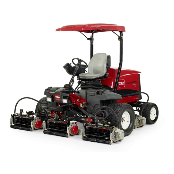
Toro Reelmaster 5010-H Operator's Manual
Traction unit
Hide thumbs
Also See for Reelmaster 5010-H:
- Diagnostic manual (476 pages) ,
- Service manual (335 pages) ,
- Operator's manual (128 pages)

Related Manuals for Toro Reelmaster 5010-H


Summary of Contents for Toro Reelmaster 5010-H
- Page 1 Form No. 3450-193 Rev B Reelmaster ® 5010-H Traction Unit Model No. 03674—Serial No. 410400000 and Up *3450-193* Register at www.Toro.com. Original Instructions (EN)
- Page 2 It is a violation of California Public Resource Code additional information, contact an Authorized Service Section 4442 or 4443 to use or operate the engine on Dealer or Toro Customer Service and have the model and serial numbers of your product ready. Figure 1...
-
Page 3: Table Of Contents
Contents Separating the Generator Cooling-Air Shrouds ............45 Assembling the Generator Cooling-Air Safety ............... 4 Shrouds ............45 General Safety ........... 4 Jacking Point Locations ........46 Safety and Instructional Decals ......5 Lubrication ............47 Setup ...............11 Greasing the Bearings and Bushings ....47 1 Preparing the Machine........11 Engine Maintenance ........... -
Page 4: Safety
Safety Checking the Hydraulic Lines and Hoses............68 Changing the Charge Filter....... 68 This machine has been designed in accordance Checking for Leaks ........... 69 with EN ISO 5395 (when you complete the setup Hydraulic Fluid Capacity ........69 procedures) and ANSI B71.4-2017. Changing the Hydraulic Fluid ...... -
Page 5: Safety And Instructional Decals
Safety and Instructional Decals Safety decals and instructions are easily visible to the operator and are located near any area of potential danger. Replace any decal that is damaged or missing. decal106-6754 decalbatterysymbols 106-6754 Battery Symbols 1. Warning—do not touch the hot surface. Some or all of these symbols are on your battery 2. - Page 6 decal110-8921 110-8921 1. Traction unit speed 2. Slow 3. Fast decal110-9642 110-9642 1. Stored energy hazard—read the Operator's Manual. 2. Move the cotter pin to the hole closest to the rod bracket and then remove the lift arm and pivot yoke. decal125-8754 125–8754 1.
- Page 7 decal145-5261 145-5261 1. Read the 4. Electric 7. TEC controller Operator's Manual for fuse information. 2. Power point (12 5. Engine start 8. TEC controller 3. Headlights 6. Air ride seat 9. TEC controller suspension (optional) decal133-2930 133-2930 1. Warning—do not operate this machine unless you are trained. 4. Tipping hazard—drive slowly when turning; do not turn sharply while traveling fast;...
- Page 8 CE Machine decal133-2931 133-2931 Note: This machine complies with the industry standard stability test in the static lateral and longitudinal tests with the maximum recommended slope indicated on the decal. Review the instructions for operating the machine on slopes in the Operator’s Manual as well as the conditions in which you would operate the machine to determine whether you can operate the machine in the conditions on that day and at that site.
- Page 9 decal136-3721 136-3721 1. Read the Operator’s 6. Engine air filter 11. Engine coolant 16. Fluids Manual for lubrication information. 2. Brake functions 7. Engine oil 12. Engine oil level 17. Capacity 8. Fan belt 13. Fuel 3. Check every 8 hours. 18.
- Page 10 decal136-3732 136-3732 1. Acute toxicity 4. Corrosive to metals/skin corrosion 2. Aspiration hazard 5. Environmental toxicity 3. Flammable gases...
-
Page 11: Setup
Setup Loose Parts Use the chart below to verify that all parts have been shipped. Procedure Description Qty. – No parts required Prepare the machine. – No parts required Adjust the control-arm position. Cutting units Install the cutting units. Mount the finishing kits (finishing kits Finishing kit (sold separately) are sold separately). -
Page 12: Adjusting The Control-Arm Position
Important: Failure to properly grease the machine will result in premature failure of critical parts. Open the hood and check the coolant level; refer Installing the Cutting Units Checking the Coolant Level (page 64). Check the level of the engine-oil level, and close and latch the hood;... - Page 13 g375232 Figure 5 1. 48 V system connector 2. Battery-disconnect jumper At each cutting unit lift arm, remove the snapper pin that secures the cap to the pivot yoke, and remove the cap (Figure g027133 Figure 7 1. Counterweight Coat the carrier-frame shaft with clean grease (Figure g003975 Figure 6...
- Page 14 Positioning the Turf Compensating Spring Cutting Units 2 and 4 g375690 Figure 11 g378839 Figure 9 1. Carriage bolt (3/8 x 1-1/4 3. Flange locknut (3/8 inch) inches) 1. Cutting unit 1 5. Cutting unit 5 2. Turf-compensator bracket 6. Reel motor 2.
- Page 15 g375694 Figure 13 g375274 Figure 15 1. Flange locknut (3/8 inch) 3. Capscrew 1. Cap 3. Pivot yoke 2. Right tab (Carrier frame) 2. Snapper pin 4. Carrier frame shaft Align the holes in the turf-compensator bracket Assemble the pivot yoke onto the carrier frame with the holes in the cutting-unit frame (Figure shaft.
- Page 16 Installing the Rear Cutting Units to the Lift Arms Cutting Units adjusted for a 1.2 cm (3/4 inch) or Higher Height of Cut Slide a cutting unit under the lift arm (Figure 17). g375251 Figure 18 1. Snapper-pin positions 3. Slot (pivot yoke) 2.
- Page 17 g375239 Figure 22 1. Lynch pin 3. Lift arm 2. Lift-arm shaft 4. Washer Insert the pivot yoke into the lift arm, and secure g375237 shaft to the arm with the lynch pin and washer. Figure 20 Repeat steps through for the other rear 1.
-
Page 18: Mounting The Finishing Kits
Important: Make sure that the reel-motor Use the following diagram to determine the cable is not twisted, kinked, or at risk of positions of cutting units and reel motors. being pinched. g316995 Figure 25 1. Center front cutting unit 4. Front left cutting unit 2. - Page 19 g316962 Figure 26 Left front cutting unit (#4) g316976 Figure 28 3. Bulkhead bracket 1. Extra flange nut Center front cutting unit (#1) 2. Connector plate (Underside of machine shown) 1. Connector plate 3. Bulkhead bracket Repeat the procedure on the remaining 4 2.
-
Page 20: Using The Cutting-Unit Kickstand
g003985 Figure 31 g316998 1. Cutting-unit kickstand Figure 30 Right rear cutting unit (#3) Secure the kickstand to the chain bracket with the 1. Extra flange nut 3. Connector plate snapper pin (Figure 32). 2. Bulkhead bracket Using the Cutting-Unit Kickstand Parts needed for this procedure: Cutting-unit kickstand... -
Page 21: Installing The 48 V Disconnect Jumper And Closing The Seat Base
Installing the 48 V Installing the CE Hood Lock Disconnect Jumper and Parts needed for this procedure: Closing the Seat Base Hood lock, seal, and jam nut Washer No Parts Required Procedure Procedure Unlatch and raise the hood. Apply dielectric grease to the contact surfaces of the battery disconnect jumper (Figure 33). -
Page 22: Applying The Ce Decals
g375337 Figure 37 1. CE decal 2. Hood lock g375326 Figure 36 Remove the backing from the CE decal. 1. Hood latch 3. Seal Apply the decal to the hood. 2. Nut 4. Washer Applying the Year of Production Remove the nut from the lock. Decal Outside the hood, insert the hook end of the latch through the hole in the hood. -
Page 23: Product Overview
Product Overview g260768 Figure 40 g375338 Figure 39 1. Engine hood 5. Seat adjustments 1. CE warning decal 2. Warning decal 133-293 2. Operator's seat 6. Front cutting units 3. Control arm 7. Rear cutting units 4. Steering wheel Remove the backing from the CE warning decal. Apply the CE warning decal over decal 133-293. - Page 24 Tilt-Steering Pedal To tilt the steering wheel towards you, press the foot pedal (Figure 41) down, pull the steering tower toward you to the most comfortable position, and release the pedal. Engine-Speed Switch The engine-speed switch has 2 modes to change the engine speed (Figure 42).
-
Page 25: Seat Controls
Enable/Disable Switch Use the enable/disable switch (Figure 42) in conjunction with the lower mow/raise control lever to operate the cutting units. Headlight Switch Pivot the switch downward to turn on the headlights (Figure 42). Power Point The power point is a 12 V power supply for electronic devices (Figure 43). - Page 26 InfoCenter Icon Description Seat-Position Lever Pull the seat-position lever (Figure 45) to move the SERVICE DUE Indicates when scheduled service should be performed seat forward and rearward. Release the lever to lock the seat position. Hour meter Weight-Adjusting Knob Info icon Rotate the weight-adjusting knob until your weight is displayed in the window of the weight gauge.
- Page 27 Faults The Faults menu contains a list of the recent machine faults. Refer to the Service Manual or Front Backlap contact your Toro Distributor for more information on Rear Backlap the Faults menu and the information contained there. The cutting units are lowering.
- Page 28 Displays the calculated reel If you changed the PIN code and forgot the code, speed position for the front reels. The reels can also be contact your authorized Toro distributor for assistance. manually adjusted. From the M , use the center button to...
- Page 29 Setting the Service Due Timer In the S , use the center button to ETTINGS scroll down to the P and press ROTECTED The service due timer resets the service due the right button (Figure 48A). hours after a scheduled maintenance procedure is performed.
-
Page 30: Specifications
Setting the Economy Mode To ensure optimum performance and continued safety certification of the machine, use only genuine Toro From the Main Menu, use the center button to replacement parts and accessories. Replacement scroll down to the Settings Menu. -
Page 31: Before Operation
Operation • Do not store the machine or fuel container where there is an open flame, spark, or pilot light, such as on a water heater or other appliance. Note: Determine the left and right sides of the • If you spill fuel, do not attempt to start the engine; machine from the normal operating position. -
Page 32: Adding Fuel
Important: If your machine fails any of the interlock switch checks, contact your authorized Park the machine on a level surface, lower the Toro distributor. cutting units, shut off the engine, and remove the key. Preparing the Machine Using a clean rag, clean the area around the Drive the machine slowly to an open area. -
Page 33: Breaking In The Machine
Breaking in the Machine • Slow down and use caution when making turns and crossing roads and sidewalks with the To ensure optimum performance of the parking brake machine. Always yield the right-of-way. system, burnish (break in) the brakes before use. •... -
Page 34: Starting The Engine
Changes in the terrain can result in a change in Run the engine at low idle speed until it warms slope operation for the machine. – Avoid starting, stopping, or turning the machine on slopes. Avoid making sudden changes in Shutting Off the Engine speed or direction. -
Page 35: Adjusting The Lift-Arm Counterbalance
Note: When operating on rough terrain Repeat steps at the other counterbalance decrease the spring length by 13 mm (1/2 inch). spring. Ground following will be slightly decreased. Note: Adjusting the Lift-Arm The turf compensation setting will need to be reset if the HOC setting or the Turnaround Position Aggressiveness of Cut setting is changed. -
Page 36: Setting The Reel Speed
Setting the Reel Speed To achieve a consistent, high quality-of-cut and a uniform after cut appearance, it is important that you set the reel speed to the proper setting. Adjust the reel speed as follows: In the InfoCenter, under the settings menu, enter the blade count, mow speed, and HOC to calculate the proper reel speed. -
Page 37: Understanding The Diagnostic Light
Understanding the Mowing Diagnostic Light Start the engine and move the engine-speed switch to the F position. Move the Enable/Disable switch to the E position and use the Lower Mow/Raise The machine is equipped with a diagnostic light NABLE lever to control the cutting units (the front cutting units which indicates if the electronic controller senses an are timed to lower before the rear cutting units). -
Page 38: Tie-Down Point Locations
Tie-Down Point Locations At the variable-displacement pump, rotate the bypass-valve bolt 1-1/2 turns to open and allow oil to bypass internally (Figure 58). Note: The bypass valve is located at the left side of the pump. By bypassing the fluid, you can move the machine slowly without damaging the transmission. -
Page 39: Maintenance
– Wait for all movement to stop. • To ensure safe, optimal performance of the – Allow the machine to cool before adjusting, machine, use only genuine Toro replacement servicing, cleaning, or storing it. parts. Replacement parts made by other •... - Page 40 Maintenance Service Maintenance Procedure Interval • Torque the wheel lug nuts to 94 to 122 N∙m (70 to 90 ft-lb). Every 250 hours • Service the air cleaner. (more frequently in extremely dirty or dusty conditions). Service the air cleaner earlier if the air-cleaner indicator shows red. •...
-
Page 41: Daily Maintenance Checklist
Daily Maintenance Checklist Duplicate this page for routine use. Maintenance For the week of: Check Item Mon. Tues. Wed. Thurs. Fri. Sat. Sun. Check the safety interlock operation. Check the brake operation. Check the levels of the engine oil and fuel. Check the cooling-system fluid level. - Page 42 Important: Refer to your engine operator’s manual for additional maintenance procedures. Notation for Areas of Concern Inspection performed by: Item Date Information...
-
Page 43: Pre-Maintenance Procedures
Pre-Maintenance Closing the Hood Procedures Carefully rotate the hood closed (Figure 60). Preparing for Maintenance Park the machine on a level surface. Engage the parking brake. Press the enable/disable switch to the position. ISENGAGE Move the lower mow/raise control to the M position. -
Page 44: Closing The Screen
Closing the Screen Close and latch the screen (Figure 62). g369008 Figure 64 1. Prop rod 2. Rod-guide plate g378174 Figure 62 1. Ball pin 2. Screen latch Lowering the Seat Insert the ball pin through the screen latch. Rotate the seat slightly, and lift the prop rod out of the dent of the seat support slot (Figure 65). -
Page 45: Separating The Generator Cooling-Air Shrouds
Separating the Generator Cooling-Air Shrouds Remove the 4 flange-head capscrews and 4 flange locknuts that secure the upper and lower generator cooling-air shrouds (Figure 66). g378915 Figure 67 1. Upper generator 3. Flange (generator cover) cooling-air shroud 4. Lower generator 2. -
Page 46: Jacking Point Locations
g375763 Figure 69 1. Front of the machine 3. Rear-axle tube 2. Jack brackets (front-axle 4. Back of the machine tube) g378913 • Front—the jack brackets of the front-axle tube Figure 68 (Figure 69). 1. Flange-head capscrew 3. Flange locknut •... -
Page 47: Lubrication
Lubrication Greasing the Bearings and Bushings Service Interval: Every 50 hours (and immediately g012150 after every washing). Figure 71 Grease Specification: No. 2 lithium grease Prepare the machine for maintenance; refer to • Lift-arm pivots (1 each) (Figure Preparing for Maintenance (page 43). - Page 48 g011615 Figure 77 Assemble the generator cooling-air shrouds; refer to Assembling the Generator Cooling-Air Shrouds (page 45). Lower and latch the seat; refer to Lowering the Seat (page 44). Close and latch the hood; refer to Closing the Hood (page 43).
-
Page 49: Engine Maintenance
Engine Maintenance Engine Safety • Shut off the engine before checking the oil or adding oil to the crankcase. • Do not change the governor speed or overspeed the engine. Checking the Air Filter Service Interval: Before each use or daily Prepare the machine for maintenance;... -
Page 50: Resetting The Air Filter Service Indicator
Preferred oil: SAE 15W-40 (above 0°F) • Alternate oil: SAE 10W-30 or 5W-30 (all temperatures) Toro Premium Engine Oil is available from your authorized Toro distributor in either 15W-40 or 10W-30 viscosity grades. Checking the Level of the Engine Oil... -
Page 51: Crankcase Oil Capacity
Crankcase Oil Capacity Open the hood; refer to Opening the Hood (page 43). Approximately 3.3 L (3.5 US qt) with the filter. Check the level of the engine oil (Figure 82). Changing the Engine Oil and Filter Service Interval: After the first 50 hours—Change the engine oil and filter. -
Page 52: Fuel System Maintenance
Fuel System Maintenance DANGER Under certain conditions, fuel and fuel vapors are highly flammable and explosive. A fire or explosion from fuel can burn you and others and can cause property damage. • Fill the fuel tank outdoors, in an open area, when the engine is off and is cold. -
Page 53: Replacing The Water-Separator Filter
Open the valve and drain the water and Close and latch the hood; Closing the Hood contaminants from the separator. (page 43). Close the valve of the fuel-water separator. Bleeding the Fuel System Start the engine and check for leaks. Note: Repair all leaks. -
Page 54: Draining The Fuel Tank
Draining the Fuel Tank Service Interval: Every 800 hours Drain and clean the fuel tank if the fuel system becomes contaminated. Before storage Drain and clean the fuel tank if you store the machine for an extended period. Fuel-tank capacity: 53 L (14 US gallons) Prepare the machine for maintenance;... - Page 55 Cleaning the Installing the Fuel-Pickup Tube Clean the screen at the end of the fuel pick-up tube (Figure 92). g373882 Figure 90 1. Hoses 3. Fitting (fuel sender) 2. Clamp Loosen the fuel-sender cap (Figure 91). g373881 Figure 92 Carefully assemble the fuel pick-up tube and float into the fuel tank (Figure 93).
- Page 56 g373882 Figure 94 1. Hoses 3. Fitting (fuel sender) 2. Clamp g373885 Figure 96 Plug the connector of the fuel-sender harness 1. Fuel-sender cover 3. Fuel tank into the connector of the machine wire harness 2. Phillips-head screw (Figure 95). g373884 Figure 95 1.
-
Page 57: Electrical System Maintenance
Electrical System Maintenance Important: Before welding on the machine, disconnect all cables from the battery, both wire harness plugs from the electronic control module, and the terminal connector from the alternator to prevent damage to the electrical system. Electrical System Safety •... -
Page 58: Charging The 12 V Battery
Replacing a 12 V Apply a coat of Grafo 112X (skin-over) grease, Toro Part No. 505-47 to the battery posts and Fuse-Block Fuse battery-cable clamps. Slide the rubber boot over the positive The fuse block is in the control arm. -
Page 59: Replacing A 48 V Cutting Unit Fuse
Assemble the control-arm cover to the control arm, and secure the cover with the 2 latches. Replacing a 48 V Cutting Unit Fuse Prepare the machine for maintenance; refer to Preparing for Maintenance (page 43). Unlatch and open the hood; refer to Opening the Hood (page 43). -
Page 60: Replacing The Tec Fuse
g379039 Figure 104 1. Cap 3. Fuse holder (labeled2A g379038 TEC P Figure 103 2. Fuse 1. Cap 3. Fuse holder (labeled 10 A 125 V) NABLE Replace the open fuse with a fuse of the same 2. Fuse type and amperage rating. Assemble the cap to the in-line fuse holder. -
Page 61: Drive System Maintenance
Drive System Maintenance Checking the Tire Air Pressure Service Interval: Before each use or daily Important: Maintain the recommended pressure in all tires to ensure a good quality of cut and proper machine performance. Do not underinflate the tires. Prepare the machine for maintenance; refer to g378242 Preparing for Maintenance (page 43). -
Page 62: Checking The Rear-Wheel Alignment
Checking the Rear-Wheel (page 30) Jacking Point Locations (page 46). Alignment From the bottom of the machine and at the right side of the traction pump, loosen the locknut Service Interval: Every 800 hours—Check the rear that secures the neutral return-adjustment screw wheel toe-in. -
Page 63: Cooling System Maintenance
Cooling System Maintenance Cooling System Safety • Swallowing engine coolant can cause poisoning; keep out of reach from children and pets. • Discharge of hot, pressurized coolant or touching a hot radiator and surrounding parts can cause severe burns. – Always allow the engine to cool at least 15 minutes before removing the radiator cap. -
Page 64: Checking The Coolant Level
• Preferred option: If distilled water is not available, Close and latch the hood; refer to Closing the use a pre-mix coolant instead of a concentrate. Hood (page 43). • Minimum requirement: If distilled water and pre-mix coolant are not available, mix concentrated Removing Debris from the coolant with clean drinkable water. -
Page 65: Brake Maintenance
Brake Maintenance Adjusting the Parking Brakes Adjust the service brakes when there is more than 13 mm (1/2 inch) of free travel of the brake pedal, or if the brakes slip. Free travel is the distance the brake pedal moves before you feel braking-pedal resistance. Prepare the machine, refer to Preparing for g379098... -
Page 66: Adjusting The Parking-Brake Latch
g011617 Figure 115 1. Brake cables 3. Parking-brake pawl g379043 4. Brake detent 2. Screws (2) Figure 114 1. Front jam nut (brake cable) 2. Rear jam nut Press the parking-brake pedal forward until the brake detent completely engages on the brake Tighten the rear nuts to move the cable pawl (Figure... -
Page 67: Belt Maintenance
A machine using the recommended replacement fluid requires less frequent fluid and filter changes. Alternative hydraulic fluids: If Toro PX Extended Life Hydraulic Fluid is not available, you may use another conventional, petroleum-based hydraulic fluid having specifications that fall within the listed range... -
Page 68: Checking The Hydraulic-Fluid Level
Remove the cap/dipstick from the filler neck and This fluid is compatible with the elastomers used wipe it with a clean rag. in Toro hydraulic systems and is suitable for a Insert the dipstick into the filler neck; then wide-range of temperature conditions. This fluid is remove it and check the level of fluid. -
Page 69: Checking For Leaks
If the fluid becomes contaminated, contact your Toro Distributor because the system must be flushed. Contaminated fluid looks milky or black when compared to clean fluid. -
Page 70: Cutting Unit System Maintenance
• Never attempt to turn the cutting units by hand or foot while the engine is running. Note: Additional instructions and procedures on backlapping are available in the Toro Reel Mower Basics (with sharpening guidelines), Form 09168SL. Note: When backlapping, the front units all operate... - Page 71 Preparing the Machine Shut off the engine and remove the key. Adjust to the cutting units. Prepare the machine for maintenance; refer to Preparing for Maintenance (page 43). Repeat steps through 3. With the engine off, but the key in the run Repeat step for the other cutting units that you position, access the Main Menu of the...
-
Page 72: Chassis Maintenance
Extended Maintenance Chassis Maintenance Inspecting the Seat Belt Chassis and Engine Service Interval: Before each use or daily Service Interval: Every 2 years—Replace the hydraulic hoses. Inspect the seat belt for wear, cuts, and other damage. Replace the seat belt(s) if any Every 2 years—Replace the coolant hoses. -
Page 73: Cleaning
Clean the battery, terminals, and posts with a wire brush and baking-soda solution. Coat the cable terminals and battery posts with Grafo 112X skin-over grease (Toro Part No. 505-47) or petroleum jelly to prevent corrosion. Slowly charge the battery every 60 days for 24 hours to prevent lead sulfation of the battery. -
Page 74: Preparing The Engine
Preparing the Engine Drain the engine oil from the oil pan and install the drain plug. Remove and discard the oil filter. Install a new oil filter. Fill the engine with specified motor oil. Start the engine and run it at idle speed for approximately 2 minutes. - Page 75 The Toro Company (“Toro”) respects your privacy. When you purchase our products, we may collect certain personal information about you, either directly from you or through your local Toro company or dealer. Toro uses this information to fulfil contractual obligations - such as to register your warranty, process your warranty claim or to contact you in the event of a product recall - and for legitimate business purposes - such as to gauge customer satisfaction, improve our products or provide you with product information which may be of interest.
- Page 76 Countries Other than the United States or Canada Customers who have purchased Toro products exported from the United States or Canada should contact their Toro Distributor (Dealer) to obtain guarantee policies for your country, province, or state. If for any reason you are dissatisfied with your Distributor's service or have difficulty obtaining guarantee information, contact your Authorized Toro Service Center.