
Related Manuals for Bosch Rexroth IndraDyn A Series


Summary of Contents for Bosch Rexroth IndraDyn A Series
- Page 1 Electric Drives Linear Motion and and Controls Hydraulics Assembly Technologies Pneumatics Service Rexroth IndraDyn A Series R911295781 Edition 03 Asynchronous Motors MAD/MAF Project Planning Manual...
- Page 2 All rights are reserved with respect to the content of this documentation and the availability of the product. Bosch Rexroth Electric Drives and Controls GmbH Published by Bgm.-Dr.-Nebel-Str. 2 • 97816 Lohr a. Main, Germany Tel +49 (0)93 52 / 40-0 •...
-
Page 3: Table Of Contents
Rexroth IndraDyn A Table of Contents Table of Contents Introduction to the Product About this Documentation......................1-2 Additional Components ......................1-3 Feedback ..........................1-3 Standards ..........................1-3 Important directions for use Appropriate use ..........................2-1 Introduction ..........................2-1 Areas of use and application ....................2-2 Inappropriate use.......................... - Page 4 Table of Contents Rexroth IndraDyn A Characteristic Curves of MAD130B Motors................4-18 Data Sheet MAD130C ........................ 4-21 Characteristic Curves of MAD130C Motors ................4-22 Data Sheet MAD130D ........................ 4-25 Characteristic Curves of MAD130D Motors ................4-26 Data Sheet MAD160B ........................ 4-29 Characteristic Curves of MAD160B Motors................
- Page 5 Rexroth IndraDyn A Table of Contents Frame Size MAD130 ........................5-7 MAD130 without Holding Brake....................5-7 MAD130 with Brake 1 or 5....................... 5-8 MAD130 with Fan Cowl, without Holding Brake..............5-9 MAD130 with Fan Cowl and Brake 1 or 5 ................5-9 MAD130 in ATEX Design, without Holding Brake ..............
- Page 6 Table of Contents Rexroth IndraDyn A 5.10 Frame Size MAF225........................5-41 MAF225 (without Holding Brake) ..................5-41 Type Codes IndraDyn A Introduction ........................... 6-1 Definition..........................6-1 Type Code MAD100 ........................6-4 Type Code MAD130 ........................6-6 Type Code MAD160 ........................6-8 Type Code MAD180 ........................
- Page 7 Rexroth IndraDyn A Table of Contents Vibration and Shock........................9-2 Vibration........................... 9-2 Shock............................9-3 Compatibility with Foreign Material....................9-3 Protection Class..........................9-4 Frame Shape and Installation Position..................9-5 Foot Assembly......................... 9-6 Vertical Installation Position..................... 9-6 Housing Painting........................... 9-8 Motor Cooling System ........................9-8 Fan............................
- Page 8 Table of Contents Rexroth IndraDyn A 10 Handling and Transport 10-1 10.1 Supplied Condition........................10-1 Factory Inspection ......................... 10-1 Inspection by Customer......................10-1 10.2 Identification..........................10-2 10.3 Designation ..........................10-2 10.4 Transport and Storage........................ 10-3 General Information....................... 10-3 Notes for Transport........................ 10-3 Information on Storage ......................
- Page 9 Rexroth IndraDyn A Table of Contents EEx p Control Device for Motor Scavenging ................. 13-8 Connection cable ........................13-9 13.7 Mechanical Attachment ......................13-9 13.8 Connection Techniques ......................13-11 Power Connection ....................... 13-11 Encoder Connection ......................13-13 Grounding Conductor ......................13-14 Coolant Connection to MAD Motors ..................
- Page 10 VIII Table of Contents Rexroth IndraDyn A DOK-MOTOR*-MAD/MAF****-PR03-EN-P...
-
Page 11: Introduction To The Product
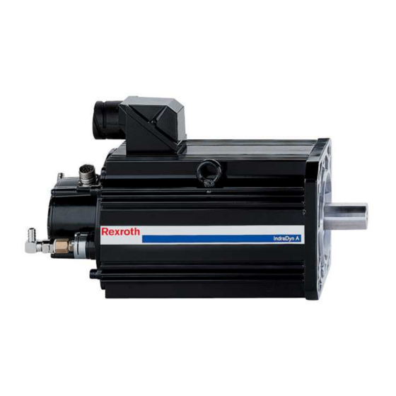
Rexroth IndraDyn A Introduction to the Product Introduction to the Product The Rexroth motor generation IndraDyn A consists of asynchronous box motors with squirrel-cage rotor; it is available as MAD series with surface ventilation by solidly connected fan unit. MAD.jpg Fig. -
Page 12: About This Documentation
Introduction to the Product Rexroth IndraDyn A About this Documentation Document Structure This documentation includes safety regulations, technical data and operating instructions. The following table provides an overview of the contents of this documentation. Sect. Title Contents Introduction to the product and Introduction notes Important Instructions on Use... -
Page 13: Additional Components
Rexroth IndraDyn A Introduction to the Product Additional Components Documentation for external systems which are connected to BOSCH REXROTH components are not included in the scope of delivery and must be ordered directly from the corresponding manufacturers. For information on the manufacturers, see chapter 9 ”Application Notes”. - Page 14 Introduction to the Product Rexroth IndraDyn A DOK-MOTOR*-MAD/MAF****-PR03-EN-P...
-
Page 15: Important Directions For Use
The user alone carries all responsibility of the risks. Before using Bosch Rexroth products, make sure that all the pre- requisites for appropriate use of the products are satisfied: • Personnel that in any way, shape or form uses our products must first read and understand the relevant safety instructions and be familiar with appropriate use. -
Page 16: Areas Of Use And Application
Important directions for use Rexroth IndraDyn A Areas of use and application Asynchronous motors of the IndraDyn A line made by Bosch Rexroth are designed to be used as rotary main-spindle and servo-drive motors. Typical applications are in: • machine tools, •... -
Page 17: Safety Instructions For Electric Drives And Controls
Follow these safety instructions at all times. • Bosch Rexroth AG is not liable for damages resulting from failure to observe the warnings provided in this documentation. • Read the operating, maintenance and safety instructions in your language before starting up the machine. - Page 18 Safety Instructions for Electric Drives and Controls Rexroth IndraDyn A • The devices have been designed for installation in industrial machinery. • The ambient conditions given in the product documentation must be observed. • Only use safety-relevant applications that are clearly and explicitly approved in the Project Planning Manual.
-
Page 19: Explanation Of Warning Symbols And Degrees Of Hazard Seriousness
Rexroth IndraDyn A Safety Instructions for Electric Drives and Controls Explanation of Warning Symbols and Degrees of Hazard Seriousness The safety instructions describe the following degrees of hazard seriousness. The degree of hazard seriousness informs about the consequences resulting from non-compliance with the safety instructions: Warning symbol with signal Degree of hazard seriousness according word... -
Page 20: Hazards By Improper Use
Safety Instructions for Electric Drives and Controls Rexroth IndraDyn A Hazards by Improper Use High electric voltage and high working current! Risk of death or severe bodily injury by electric shock! DANGER Dangerous movements! Danger to life, severe bodily harm or material damage by unintentional motor movements! DANGER High electric voltage because of incorrect... -
Page 21: Instructions With Regard To Specific Dangers
Rexroth IndraDyn A Safety Instructions for Electric Drives and Controls Instructions with Regard to Specific Dangers Protection Against Contact with Electrical Parts Note: This section only concerns devices and drive components with voltages of more than 50 Volt. Contact with parts conducting voltages above 50 Volts can cause personal danger and electric shock. -
Page 22: Protection Against Electric Shock By Protective Low Voltage (Pelv)
Safety Instructions for Electric Drives and Controls Rexroth IndraDyn A European countries: according to EN 50178/ 1998, section 5.3.2.3. USA: See National Electrical Code (NEC), National Electrical Manufacturers' Association (NEMA), as well as local engineering regulations. The operator must observe all the above regulations at any time. -
Page 23: Protection Against Dangerous Movements
Rexroth IndraDyn A Safety Instructions for Electric Drives and Controls Protection Against Dangerous Movements Dangerous movements can be caused by faulty control of connected motors. Some common examples are: • improper or wrong wiring of cable connections • incorrect operation of the equipment components •... - Page 24 Safety Instructions for Electric Drives and Controls Rexroth IndraDyn A Dangerous movements! Danger to life, risk of injury, severe bodily harm or material damage! ⇒ For the above reasons, ensure personal safety by means of qualified and tested higher-level monitoring DANGER devices or measures integrated in the installation.
-
Page 25: Protection Against Magnetic And Electromagnetic Fields During Operation And Mounting
Rexroth IndraDyn A Safety Instructions for Electric Drives and Controls ⇒ Disconnect electrical power to the equipment using a master switch and secure the switch against reconnection for: maintenance and repair work cleaning of equipment - long periods of discontinued equipment use ⇒... -
Page 26: Protection Against Contact With Hot Parts
3-10 Safety Instructions for Electric Drives and Controls Rexroth IndraDyn A Protection Against Contact with Hot Parts Hot surfaces at motor housings, on drive controllers or chokes! Danger of injury! Danger of burns! ⇒ Do not touch surfaces of device housings and CAUTION chokes in the proximity of heat sources! Danger of burns! -
Page 27: Protection During Handling And Mounting
3-11 Rexroth IndraDyn A Safety Instructions for Electric Drives and Controls Protection During Handling and Mounting In unfavorable conditions, handling and assembling certain parts and components in an improper way can cause injuries. Risk of injury by improper handling! Bodily injury by bruising, shearing, cutting, hitting! ⇒... -
Page 28: Protection Against Pressurized Systems
3-12 Safety Instructions for Electric Drives and Controls Rexroth IndraDyn A Protection Against Pressurized Systems According to the information given in the Project Planning Manuals, motors cooled with liquid and compressed air, as well as drive controllers, can be partially supplied with externally fed, pressurized media, such as compressed air, hydraulics oil, cooling liquids, and cooling lubricating agents. -
Page 29: Technical Data
Technical Data Technical Data Operating Modes Bosch Rexroth motors are documented according to the test criteria and measuring methods of EN 60034-1. Stated technical data refer to operating modes S1 (continuous operation) and S6 (periodic operation), each with surface cooling through direct-connected fan units or liquid cooling. -
Page 30: Operating Behavior
Technical Data Rexroth IndraDyn A Operating Behavior In the following, parameters and characteristic curves of the IndraDyn A series and specifications of the motor data sheet are explained. Parameters Available torque that can be output at the rated speed in operating mode Rated torque M S1 (continuous operation). - Page 31 Rexroth IndraDyn A Technical Data The moment of inertia of the rotor without bearing, brake and encoder. Rotor moment of inertia J Unit = kgm². Mass of the motor in standard version, without holding brake, specified in Motor mass m kilograms (kg).
- Page 32 Technical Data Rexroth IndraDyn A Characteristic Curve AsyncCurve.EPS mechanical output in kilowatts [kW] torque available on the output shaft, in Newton meters [Nm] motor speed, in revolutions per minute [min (1): key speed (n in data sheet) (2): rated speed (n (3): max.
-
Page 33: Data Sheet Mad100B
Rexroth IndraDyn A Technical Data Data Sheet MAD100B Description Symbol Unit MAD100B Motor data Winding 0050 0100 0150 0200 0250 Rated torque Rated power Rated current 12.9 14.6 16.2 Rated speed 1000 1500 2000 2500 Key speed 1000 1500 2000 Maximum torque Maximum output 12.1... -
Page 34: Characteristic Curves Of Mad100B Motors
Technical Data Rexroth IndraDyn A Characteristic Curves of MAD100B Motors MAD100B-0050 1000 1500 2000 2500 3000 Drehzahl / Speed [min-1] Mit Regelgerät HMS01.1N-W0020 an Versorger HNV01.1E-W0120 an 3x AC400V (-5%) With Drive Controller HMS01.1N-W0020 at HNV01.1E-W0120 with main connection 3x AC400V (-5%) Kennl_MAD100B-0050.WMF Fig. - Page 35 Rexroth IndraDyn A Technical Data MAD100B-0150 1000 2000 3000 4000 5000 6000 7000 8000 9000 Drehzahl / Speed [min-1] Mit Regelgerät HMS01.1N-W0036 an Versorger HNV01.1E-W0120 an 3x AC400V (-5%) With Drive Controller HMS01.1N-W0036 at HNV01.1E-W0120 with main connection 3x AC400V (-5%) Kennl_MAD100B-0150.WMF Fig.
- Page 36 Technical Data Rexroth IndraDyn A MAD100B-0250 1000 2000 3000 4000 5000 6000 7000 8000 9000 Drehzahl / Speed [min-1] Mit Regelgerät HMS01.1N-W0036 an Versorger HNV01.1E-W0120 an 3x AC400V (-5%) With Drive Controller HMS01.1N-W0036 at HNV01.1E-W0120 with main connection 3x AC400V (-5%) Kennl_MAD100B-0250.WMF Fig.
-
Page 37: Data Sheet Mad100C
Rexroth IndraDyn A Technical Data Data Sheet MAD100C Description Symbol Unit MAD100C Motor data Winding 0050 0100 0150 0200 0250 Rated torque Rated power 10.5 Rated current 13.2 19.7 25.7 27.8 Rated speed 1000 1500 2000 2500 Key speed 1000 1500 2000 Maximum torque... -
Page 38: Characteristic Curves Of Mad100C Motors
4-10 Technical Data Rexroth IndraDyn A Characteristic Curves of MAD100C Motors MAD100C-0050 1000 1500 2000 2500 3000 Drehzahl / Speed [min-1] Mit Regelgerät HMS01.1N-W0020 an Versorger HNV01.1E-W0120 an 3x AC400V (-5%) With Drive Controller HMS01.1N-W0020 at HNV01.1E-W0120 with main connection 3x AC400V (-5%) Kennl_MAD100C-0050.WMF Fig. - Page 39 4-11 Rexroth IndraDyn A Technical Data MAD100C-0150 1000 2000 3000 4000 5000 6000 7000 8000 9000 Drehzahl / Speed [min-1] Mit Regelgerät HMS01.1N-W0054 an Versorger HNV01.1E-W0120 an 3x AC400V (-5%) With Drive Controller HMS01.1N-W0054 at HNV01.1E-W0120 with main connection 3x AC400V (-5%) Kennl_MAD100C-0150.WMF Fig.
- Page 40 4-12 Technical Data Rexroth IndraDyn A MAD100C-0250 1000 2000 3000 4000 5000 6000 7000 8000 9000 Drehzahl / Speed [min-1] Mit Regelgerät HMS01.1N-W0054 an Versorger HNV01.1E-W0120 an 3x AC400V (-5%) With Drive Controller HMS01.1N-W0054 at HNV01.1E-W0120 with main connection 3x AC400V (-5%) Kennl_MAD100C-0250.WMF Fig.
-
Page 41: Data Sheet Mad100D
4-13 Rexroth IndraDyn A Technical Data Data Sheet MAD100D Description Symbol Unit MAD100D Motor data Winding 0050 0100 0150 0200 0250 Rated torque Rated power 11.3 13.1 Rated current 10.1 19.3 25.6 27.2 32.4 Rated speed 1000 1500 2000 2500 Key speed 1000 1500... -
Page 42: Characteristic Curves Of Mad100D Motors
4-14 Technical Data Rexroth IndraDyn A Characteristic Curves of MAD100D Motors MAD100D-0050 1000 1500 2000 2500 3000 Drehzahl / Speed [min-1] Mit Regelgerät HMS01.1N-W0036 an Versorger HNV01.1E-W0120 an 3x AC400V (-5%) With Drive Controller HMS01.1N-W0036 at HNV01.1E-W0120 with main connection 3x AC400V (-5%) Kennl_MAD100D-0050.WMF Fig. - Page 43 4-15 Rexroth IndraDyn A Technical Data MAD100D-0150 1000 2000 3000 4000 5000 6000 7000 8000 9000 Drehzahl / Speed [min-1] Mit Regelgerät HMS01.1N-W0054 an Versorger HNV01.1E-W0120 an 3x AC400V (-5%) With Drive Controller HMS01.1N-W0054 at HNV01.1E-W0120 with main connection 3x AC400V (-5%) Kennl_MAD100D-0150.WMF Fig.
- Page 44 4-16 Technical Data Rexroth IndraDyn A MAD100D-0250 1000 2000 3000 4000 5000 6000 7000 8000 9000 10000 11000 Drehzahl / Speed [min-1] Mit Regelgerät HMS01.1N-W0070 an Versorger HNV01.1E-W0120 an 3x AC400V (-5%) With Drive Controller HMS01.1N-W0070 at HNV01.1E-W0120 with main connection 3x AC400V (-5%) Kennl_MAD100D-0250.WMF Fig.
-
Page 45: Data Sheet Mad130B
4-17 Rexroth IndraDyn A Technical Data Data Sheet MAD130B Description Symbol Unit MAD130B Motor data Winding 0050 0100 0150 0200 0250 Rated torque Rated power 10.5 13.3 16.8 19.6 Rated current 12.8 26.9 34.9 47.2 Rated speed 1000 1500 2000 2500 Key speed 1000... -
Page 46: Characteristic Curves Of Mad130B Motors
4-18 Technical Data Rexroth IndraDyn A Characteristic Curves of MAD130B Motors MAD130B-0050 1000 1500 2000 2500 3000 Drehzahl / Speed [min-1] Mit Regelgerät HMS01.1N-W0036 an Versorger HNV01.1E-W0120 an 3x AC400V (-5%) With Drive Controller HMS01.1N-W0036 at HNV01.1E-W0120 with main connection 3x AC400V (-5%) Kennl_MAD130B-0050.WMF Fig. - Page 47 4-19 Rexroth IndraDyn A Technical Data MAD130B-0150 500 1000 1500 2000 2500 3000 3500 4000 4500 5000 5500 6000 6500 7000 7500 Drehzahl / Speed [min-1] Mit Regelgerät HMS01.1N-W0150 an Versorger HNV01.1E-W0120 an 3x AC400V (-5%) With Drive Controller HMS01.1N-W0150 at HNV01.1E-W0120 with main connection 3x AC400V (-5%) Kennl_MAD130B-0150.WMF Fig.
- Page 48 4-20 Technical Data Rexroth IndraDyn A MAD130B-0250 500 1000 1500 2000 2500 3000 3500 4000 4500 5000 5500 6000 6500 7000 7500 Drehzahl / Speed [min-1] Mit Regelgerät HMS01.1N-W0150 an Versorger HNV01.1E-W0120 an 3x AC400V (-5%) With Drive Controller HMS01.1N-W0150 at HNV01.1E-W0120 with main connection 3x AC400V (-5%) Kennl_MAD130B-0250.WMF Fig.
-
Page 49: Data Sheet Mad130C
4-21 Rexroth IndraDyn A Technical Data Data Sheet MAD130C Description Symbol Unit MAD130C Motor data Winding 0050 0100 0150 0200 0250 Rated torque Rated power 13.1 18.4 26.2 Rated current 19.7 36.2 48.9 Rated speed 1000 1500 2000 2500 Key speed 1000 1500 2000... -
Page 50: Characteristic Curves Of Mad130C Motors
4-22 Technical Data Rexroth IndraDyn A Characteristic Curves of MAD130C Motors MAD130C-0050 1000 1500 2000 2500 3000 Drehzahl / Speed [min-1] Mit Regelgerät HMS01.1N-W0070 an Versorger HNV01.1E-W0120 an 3x AC400V (-5%) With Drive Controller HMS01.1N-W0070 at HNV01.1E-W0120 with main connection 3x AC400V (-5%) Kennl_MAD130C-0050.WMF Fig. - Page 51 4-23 Rexroth IndraDyn A Technical Data MAD130C-0150 500 1000 1500 2000 2500 3000 3500 4000 4500 5000 5500 6000 6500 7000 7500 Drehzahl / Speed [min-1] Mit Regelgerät HMS01.1N-W0150 an Versorger HNV01.1E-W0120 an 3x AC400V (-5%) With Drive Controller HMS01.1N-W0150 at HNV01.1E-W0120 with main connection 3x AC400V (-5%) Kennl_MAD130C-0150.WMF Fig.
- Page 52 4-24 Technical Data Rexroth IndraDyn A MAD130C-0250 1000 1500 2000 2500 3000 3500 4000 4500 5000 5500 6000 6500 7000 7500 Drehzahl / Speed [min-1] Mit Regelgerät HMS01.1N-W0150 an Versorger HNV01.1E-W0120 an 3x AC400V (-5%) With Drive Controller HMS01.1N-W0150 at HNV01.1E-W0120 with main connection 3x AC400V (-5%) Kennl_MAD130C-0250.WMF Fig.
-
Page 53: Data Sheet Mad130D
4-25 Rexroth IndraDyn A Technical Data Data Sheet MAD130D Description Symbol Unit MAD130D Motor data Winding 0050 0100 0150 0200 0250 Rated torque Rated power 17.8 24.3 31.4 31.4 Rated current 24.2 43.7 61.5 71.3 Rated speed 1000 1500 2000 2500 Key speed 1000... -
Page 54: Characteristic Curves Of Mad130D Motors
4-26 Technical Data Rexroth IndraDyn A Characteristic Curves of MAD130D Motors MAD130D-0050 1000 1500 2000 2500 3000 Drehzahl / Speed [min-1] Mit Regelgerät HMS01.1N-W0054 an Versorger HNV01.1E-W0120 an 3x AC400V (-5%) With Drive Controller HMS01.1N-W0054 at HNV01.1E-W0120 with main connection 3x AC400V (-5%) Kennl_MAD130D-0050.WMF Fig. - Page 55 4-27 Rexroth IndraDyn A Technical Data MAD130D-0150 500 1000 1500 2000 2500 3000 3500 4000 4500 5000 5500 6000 6500 7000 7500 Drehzahl / Speed [min-1] Mit Regelgerät HMS01.1N-W0150 an Versorger HNV01.1E-W0120 an 3x AC400V (-5%) With Drive Controller HMS01.1N-W0150 at HNV01.1E-W0120 with main connection 3x AC400V (-5%) Kennl_MAD130D-0150.WMF Fig.
- Page 56 4-28 Technical Data Rexroth IndraDyn A MAD130D-0250 500 1000 1500 2000 2500 3000 3500 4000 4500 5000 5500 6000 6500 7000 7500 Drehzahl / Speed [min-1] Mit Regelgerät HMS01.1N-W0210 an Versorger HNV01.1E-W0120 an 3x AC400V (-5%) With Drive Controller HMS01.1N-W0210 at HNV01.1E-W0120 with main connection 3x AC400V (-5%) Kennl_MAD130D-0250.WMF Fig.
-
Page 57: Data Sheet Mad160B
4-29 Rexroth IndraDyn A Technical Data Data Sheet MAD160B Description Symbol Unit MAD160B Motor data Winding 0050 0100 0150 0200 Rated torque Rated power 11.5 20.9 29.8 33.5 Rated current 26.1 43.5 61.6 75.8 Rated speed 1000 1500 2000 Key speed 1000 1500 Maximum torque... -
Page 58: Characteristic Curves Of Mad160B Motors
4-30 Technical Data Rexroth IndraDyn A Characteristic Curves of MAD160B Motors MAD160B-0050 1000 1500 2000 2500 3000 Drehzahl / Speed [min-1] Mit Regelgerät HMS01.1N-W0054 an Versorger HNV01.1E-W0120 an 3x AC400V (-5%) With Drive Controller HMS01.1N-W0054 at HNV01.1E-W0120 with main connection 3x AC400V (-5%) Kennl_MAD160B-0050.WMF Fig. - Page 59 4-31 Rexroth IndraDyn A Technical Data MAD160B-0150 1000 2000 3000 4000 5000 6000 Drehzahl / Speed [min-1] Mit Regelgerät HMS01.1N-W0150 an Versorger HNV01.1E-W0120 an 3x AC400V (-5%) With Drive Controller HMS01.1N-W0150 at HNV01.1E-W0120 with main connection 3x AC400V (-5%) Kennl_MAD160B-0150.WMF Fig.
-
Page 60: Data Sheet Mad160C
4-32 Technical Data Rexroth IndraDyn A 4.10 Data Sheet MAD160C Description Symbol Unit MAD160C Motor data Winding 0050 0100 0150 0200 Rated torque Rated power 12.6 23.6 33.8 Rated current 27.6 52.9 75.3 93.9 Rated speed 1000 1500 2000 Key speed 1000 1500 Maximum torque... -
Page 61: Characteristic Curves Of Mad160C Motors
4-33 Rexroth IndraDyn A Technical Data Characteristic Curves of MAD160C Motors MAD160C-0050 1000 1500 2000 2500 3000 Drehzahl / Speed [min-1] Mit Regelgerät HMS01.1N-W0070 an Versorger HNV01.1E-W0120 an 3x AC400V (-5%) With Drive Controller HMS01.1N-W0070 at HNV01.1E-W0120 with main connection 3x AC400V (-5%) Kennl_MAD160C-0050.WMF Fig. - Page 62 4-34 Technical Data Rexroth IndraDyn A MAD160C-0150 1000 2000 3000 4000 5000 6000 Drehzahl / Speed [min-1] Mit Regelgerät HMS01.1N-W0210 an Versorger HNV01.1E-W0120 an 3x AC400V (-5%) With Drive Controller HMS01.1N-W0210 at HNV01.1E-W0120 with main connection 3x AC400V (-5%) Kennl_MAD160C-0150.WMF Fig.
-
Page 63: Data Sheet Mad180C
4-35 Rexroth IndraDyn A Technical Data 4.11 Data Sheet MAD180C Description Symbol Unit MAD180C Motor data Winding 0050 0100 0150 0200 Rated torque Rated power 31.4 42.4 52.4 Rated current 38.2 88.6 104.6 Rated speed 1000 1500 2000 Key speed 1000 1500 Maximum torque... -
Page 64: Characteristic Curves Of Mad180C Motors
4-36 Technical Data Rexroth IndraDyn A Characteristic Curves of MAD180C Motors MAD180C-0050 1000 1500 2000 2500 3000 Drehzahl / Speed [min-1] Mit Regelgerät HMS01.1N-W0150 an Versorger HNV01.1E-W0120 an 3x AC400V (-5%) With Drive Controller HMS01.1N-W0150 at HNV01.1E-W0120 with main connection 3x AC400V (-5%) Kennl_MAD180C-0050.WMF Fig. - Page 65 4-37 Rexroth IndraDyn A Technical Data MAD180C-0150 1000 2000 3000 4000 5000 6000 Drehzahl / Speed [min-1] Mit Regelgerät HMS01.1N-W0210 an Versorger HNV01.1E-W0120 an 3x AC400V (-5%) With Drive Controller HMS01.1N-W0210 at HNV01.1E-W0120 with main connection 3x AC400V (-5%) Kennl_MAD180C-0150.WMF Fig.
-
Page 66: Data Sheet Mad180D
4-38 Technical Data Rexroth IndraDyn A 4.12 Data Sheet MAD180D Description Symbol Unit MAD180D Motor data Winding 0050 0100 0150 0200 Rated torque Rated power 20.4 38.7 53.4 62.8 Rated current 39.7 82.4 107.8 117.4 Rated speed 1000 1500 2000 Key speed 1000 1500... -
Page 67: Characteristic Curves Of Mad180D Motors
4-39 Rexroth IndraDyn A Technical Data Characteristic Curves of MAD180D Motors MAD180D-0050 1000 1000 1500 2000 2500 3000 Drehzahl / Speed [min-1] Mit Regelgerät HMS01.1N-W0150 an Versorger HNV01.1E-W0120 an 3x AC400V (-5%) With Drive Controller HMS01.1N-W0150 at HNV01.1E-W0120 with main connection 3x AC400V (-5%) Kennl_MAD180D-0050.WMF Fig. - Page 68 4-40 Technical Data Rexroth IndraDyn A MAD180D-0150 1000 2000 3000 4000 5000 6000 Drehzahl / Speed [min-1] Mit Regelgerät HMS01.1N-W0210 an Versorger HNV01.1E-W0120 an 3x AC400V (-5%) With Drive Controller HMS01.1N-W0210 at HNV01.1E-W0120 with main connection 3x AC400V (-5%) Kennl_MAD180D-0150.WMF Fig.
-
Page 69: Data Sheet Mad225C
4-41 Rexroth IndraDyn A Technical Data 4.13 Data Sheet MAD225C Description Symbol Unit MAD225C Motor data Winding 0050* 0100* 0150 Rated torque Rated power 33.5 64.9 Rated current Rated speed 1000 1500 Key speed 1000 Maximum torque 1450 1450 1450 Maximum output Maximum current 3000... -
Page 70: Characteristic Curve Mad225C Motor
4-42 Technical Data Rexroth IndraDyn A Characteristic Curve MAD225C Motor in preparation Fig. 4-62: Characteristic curves of MAD225C motors DOK-MOTOR*-MAD/MAF****-PR03-EN-P... -
Page 71: Data Sheet Maf100B
4-43 Rexroth IndraDyn A Technical Data 4.14 Data Sheet MAF100B Description Symbol Unit MAF100B Motor data Winding 0050 0100 0150 0200 0250 Rated torque Rated power Rated current 14.3 18.1 23.9 Rated speed 1000 1500 2000 2500 Key speed 1000 1500 2000 Maximum torque... -
Page 72: Characteristic Curves Of Mad100B Motors
4-44 Technical Data Rexroth IndraDyn A Characteristic Curves of MAD100B Motors MAF100B-0050 1000 1500 2000 2500 3000 Drehzahl / Speed [min-1] Mit Regelgerät HMS01.1N-W0036 an Versorger HMV01.1E-W0120 an 3x AC400V (-5%) With Drive Controller HMS01.1N-W0036 at HMV01.1E-W0120 with main connection 3x AC400V (-5%) Kennl_MAF100B-0050.WMF Fig. - Page 73 4-45 Rexroth IndraDyn A Technical Data MAF100B-0150 1000 2000 3000 4000 5000 6000 7000 8000 9000 Drehzahl / Speed [min-1] Mit Regelgerät HMS01.1N-W0054 an Versorger HMV01.1E-W0120 an 3x AC400V (-5%) With Drive Controller HMS01.1N-W0054 at HMV01.1E-W0120 with main connection 3x AC400V (-5%) Kennl_MAF100B-0150.WMF Fig.
- Page 74 4-46 Technical Data Rexroth IndraDyn A MAF100B-0250 1000 2000 3000 4000 5000 6000 7000 8000 9000 Drehzahl / Speed [min-1] Mit Regelgerät HMS01.1N-W0054 an Versorger HMV01.1E-W0120 an 3x AC400V (-5%) With Drive Controller HMS01.1N-W0054 at HMV01.1E-W0120 with main connection 3x AC400V (-5%) Kennl_MAF100B-0250.WMF Fig.
-
Page 75: Data Sheet Maf100C
4-47 Rexroth IndraDyn A Technical Data 4.15 Data Sheet MAF100C Description Symbol Unit MAF100C Motor data Winding 0050 0100 0150 0200 0250 Rated torque Rated power 10.4 13.4 16.2 Rated current 12.1 27.9 36.7 40.2 Rated speed 1000 1500 2000 2500 Key speed 1000... -
Page 76: Characteristic Curves Of Maf100C Motors
4-48 Technical Data Rexroth IndraDyn A Characteristic Curves of MAF100C Motors MAF100C-0050 1000 1500 2000 2500 3000 Drehzahl / Speed [min-1] Mit Regelgerät HMS01.1N-W0036 an Versorger HMV01.1E-W0120 an 3x AC400V (-5%) With Drive Controller HMS01.1N-W0036 at HMV01.1E-W0120 with main connection 3x AC400V (-5%) Kennl_MAF100C-0050.WMF Fig. - Page 77 4-49 Rexroth IndraDyn A Technical Data MAF100C-0150 1000 2000 3000 4000 5000 6000 7000 8000 9000 Drehzahl / Speed [min-1] Mit Regelgerät HMS01.1N-W0070 an Versorger HMV01.1E-W0120 an 3x AC400V (-5%) With Drive Controller HMS01.1N-W0070 at HMV01.1E-W0120 with main connection 3x AC400V (-5%) Kennl_MAF100C-0150.WMF Fig.
- Page 78 4-50 Technical Data Rexroth IndraDyn A MAF100C-0250 1000 2000 3000 4000 5000 6000 7000 8000 9000 Drehzahl / Speed [min-1] Mit Regelgerät HMS01.1N-W0150 an Versorger HMV01.1E-W0120 an 3x AC400V (-5%) With Drive Controller HMS01.1N-W0150 at HMV01.1E-W0120 with main connection 3x AC400V (-5%) Kennl_MAF100C-0250.WMF Fig.
-
Page 79: Data Sheet Maf100D
4-51 Rexroth IndraDyn A Technical Data 4.16 Data Sheet MAF100D Description Symbol Unit MAF100D Motor data Winding 0050 0100 0150 0200 0250 Rated torque Rated power 12.4 16.8 19.6 Rated current 14.5 25.1 32.7 43.1 45.8 Rated speed 1000 1500 2000 2500 Key speed... -
Page 80: Characteristic Curves Of Maf100D Motors
4-52 Technical Data Rexroth IndraDyn A Characteristic Curves of MAF100D Motors MAF100D-0050 1000 1500 2000 2500 3000 Drehzahl / Speed [min-1] Mit Regelgerät HMS01.1N-W0036 an Versorger HMV01.1E-W0120 an 3x AC400V (-5%) With Drive Controller HMS01.1N-W0036 at HMV01.1E-W0120 with main connection 3x AC400V (-5%) Kennl_MAF100D-0050.WMF Fig. - Page 81 4-53 Rexroth IndraDyn A Technical Data MAF100D-0150 1000 2000 3000 4000 5000 6000 7000 8000 9000 Drehzahl / Speed [min-1] Mit Regelgerät HMS01.1N-W0150 an Versorger HMV01.1E-W0120 an 3x AC400V (-5%) With Drive Controller HMS01.1N-W0150 at HMV01.1E-W0120 with main connection 3x AC400V (-5%) Kennl_MAF100D-0150.WMF Fig.
- Page 82 4-54 Technical Data Rexroth IndraDyn A MAF100D-0250 1000 2000 3000 4000 5000 6000 7000 8000 9000 Drehzahl / Speed [min-1] Mit Regelgerät HMS01.1N-W0150 an Versorger HMV01.1E-W0120 an 3x AC400V (-5%) With Drive Controller HMS01.1N-W0150 at HMV01.1E-W0120 with main connection 3x AC400V (-5%) Kennl_MAF100D-0250.WMF Fig.
-
Page 83: Data Sheet Maf130B
4-55 Rexroth IndraDyn A Technical Data 4.17 Data Sheet MAF130B Description Symbol Unit MAF130B Motor data Winding 0050 0100 0150 0200 0250 Rated torque Rated power 11.7 18.1 20.9 23.6 Rated current 14.7 28.4 43.7 52.7 55.5 Rated speed 1000 1500 2000 2500... -
Page 84: Characteristic Curves Of Maf130B Motors
4-56 Technical Data Rexroth IndraDyn A Characteristic Curves of MAF130B Motors MAF130B-0050 1000 1500 2000 2500 3000 Drehzahl / Speed [min-1] Mit Regelgerät HMS01.1N-W0036 an Versorger HMV01.1E-W0120 an 3x AC400V (-5%) With Drive Controller HMS01.1N-W0036 at HMV01.1E-W0120 with main connection 3x AC400V (-5%) Kennl_MAF130B-0050.WMF Fig. - Page 85 4-57 Rexroth IndraDyn A Technical Data MAF130B-0150 500 1000 1500 2000 2500 3000 3500 4000 4500 5000 5500 6000 6500 7000 7500 Drehzahl / Speed [min-1] Mit Regelgerät HMS01.1N-W0150 an Versorger HMV01.1E-W0120 an 3x AC400V (-5%) With Drive Controller HMS01.1N-W0150 at HMV01.1E-W0120 with main connection 3x AC400V (-5%) Kennl_MAF130B-0150.WMF Fig.
- Page 86 4-58 Technical Data Rexroth IndraDyn A MAF130B-0250 500 1000 1500 2000 2500 3000 3500 4000 4500 5000 5500 6000 6500 7000 7500 Drehzahl / Speed [min-1] Mit Regelgerät HMS01.1N-W0150 an Versorger HMV01.1E-W0120 an 3x AC400V (-5%) With Drive Controller HMS01.1N-W0150 at HMV01.1E-W0120 with main connection 3x AC400V (-5%) Kennl_MAF130B-0250.WMF Fig.
-
Page 87: Data Sheet Maf130C
4-59 Rexroth IndraDyn A Technical Data 4.18 Data Sheet MAF130C Description Symbol Unit MAF130C Motor data Winding 0050 0100 0150 0200 0250 Rated torque Rated power 15.7 22.8 28.3 32.7 Rated current 53.2 69.8 75.5 Rated speed 1000 1500 2000 2500 Key speed 1000... -
Page 88: Characteristic Curves Of Maf130C Motors
4-60 Technical Data Rexroth IndraDyn A Characteristic Curves of MAF130C Motors MAF130C-0050 1000 1500 2000 2500 3000 Drehzahl / Speed [min-1] Mit Regelgerät HMS01.1N-W0054 an Versorger HMV01.1E-W0120 an 3x AC400V (-5%) With Drive Controller HMS01.1N-W0054 at HMV01.1E-W0120 with main connection 3x AC400V (-5%) Kennl_MAF130C-0050.WMF Fig. - Page 89 4-61 Rexroth IndraDyn A Technical Data MAF130C-0150 500 1000 1500 2000 2500 3000 3500 4000 4500 5000 5500 6000 6500 7000 7500 Drehzahl / Speed [min-1] Mit Regelgerät HMS01.1N-W0150 an Versorger HMV01.1E-W0120 an 3x AC400V (-5%) With Drive Controller HMS01.1N-W0150 at HMV01.1E-W0120 with main connection 3x AC400V (-5%) Kennl_MAF130C-0150.WMF Fig.
- Page 90 4-62 Technical Data Rexroth IndraDyn A MAF130C-0250 500 1000 1500 2000 2500 3000 3500 4000 4500 5000 5500 6000 6500 7000 7500 Drehzahl / Speed [min-1] Mit Regelgerät HMS01.1N-W0210 an Versorger HMV01.1E-W0120 an 3x AC400V (-5%) With Drive Controller HMS01.1N-W0210 at HMV01.1E-W0120 with main connection 3x AC400V (-5%) Kennl_MAF130C-0250.WMF Fig.
-
Page 91: Data Sheet Maf130D
4-63 Rexroth IndraDyn A Technical Data 4.19 Data Sheet MAF130D Description Symbol Unit MAF130D Motor data Winding 0050 0100 0150 0200 0250 Rated torque Rated power 31.4 41.9 49.7 Rated current 32.3 72.6 93.9 Rated speed 1000 1500 2000 2500 Key speed 1000 1500... -
Page 92: Characteristic Curves Of Maf130D Motors
4-64 Technical Data Rexroth IndraDyn A Characteristic Curves of MAF130D Motors MAF130D-0050 1000 1500 2000 2500 3000 Drehzahl / Speed [min-1] Mit Regelgerät HMS01.1N-W0150 an Versorger HMV01.1E-W0120 an 3x AC400V (-5%) With Drive Controller HMS01.1N-W0150 at HMV01.1E-W0120 with main connection 3x AC400V (-5%) Kennl_MAF130D-0050.WMF Fig. - Page 93 4-65 Rexroth IndraDyn A Technical Data MAF130D-0150 500 1000 1500 2000 2500 3000 3500 4000 4500 5000 5500 6000 6500 7000 7500 Drehzahl / Speed [min-1] Mit Regelgerät HMS01.1N-W0210 an Versorger HMV01.1E-W0120 an 3x AC400V (-5%) With Drive Controller HMS01.1N-W0210 at HMV01.1E-W0120 with main connection 3x AC400V (-5%) Kennl_MAF130D-0150.WMF Fig.
- Page 94 4-66 Technical Data Rexroth IndraDyn A MAF130D-0250 500 1000 1500 2000 2500 3000 3500 4000 4500 5000 5500 6000 6500 7000 7500 Drehzahl / Speed [min-1] Mit Regelgerät HMS01.1N-W0210 an Versorger HMV01.1E-W0120 an 3x AC400V (-5%) With Drive Controller HMS01.1N-W0210 at HMV01.1E-W0120 with main connection 3x AC400V (-5%) Kennl_MAF130D-0250.WMF Fig.
-
Page 95: Data Sheet Maf160B
4-67 Rexroth IndraDyn A Technical Data 4.20 Data Sheet MAF160B Description Symbol Unit MAF160B Motor data Winding 0050 0100 0150 0200 Rated torque Rated power 14.1 27.2 39.3 50.3 Rated current 34.2 73.7 89.5 108.5 Rated speed 1000 1500 2000 Key speed 1000 1500... -
Page 96: Characteristic Curves Of Maf160B Motors
4-68 Technical Data Rexroth IndraDyn A Characteristic Curves of MAF160B Motors MAF160B-0050 1000 1500 2000 2500 3000 Drehzahl / Speed [min-1] Mit Regelgerät HMS01.1N-W0070 an Versorger HMV01.1E-W0120 an 3x AC400V (-5%) With Drive Controller HMS01.1N-W0070 at HMV01.1E-W0120 with main connection 3x AC400V (-5%) Kennl_MAF160B-0050.WMF Fig. - Page 97 4-69 Rexroth IndraDyn A Technical Data MAF160B-0150 1000 2000 3000 4000 5000 6000 Drehzahl / Speed [min-1] Mit Regelgerät HMS01.1N-W0210 an Versorger HMV01.1E-W0120 an 3x AC400V (-5%) With Drive Controller HMS01.1N-W0210 at HMV01.1E-W0120 with main connection 3x AC400V (-5%) Kennl_MAF160B-0150.WMF Fig.
-
Page 98: Data Sheet Maf160C
4-70 Technical Data Rexroth IndraDyn A 4.21 Data Sheet MAF160C Description Symbol Unit MAF160C Motor data Winding 0050 0100 0150 0200 Rated torque Rated power 17.8 47.1 59.7 Rated current 47.4 91.2 109.5 Rated speed 1000 1500 2000 Key speed 1000 1500 Maximum torque... -
Page 99: Characteristic Curves Of Maf160C Motors
4-71 Rexroth IndraDyn A Technical Data Characteristic Curves of MAF160C Motors MAF160C-0050 1000 1500 2000 2500 3000 Drehzahl / Speed [min-1] Mit Regelgerät HMS01.1N-W0150 an Versorger HMV01.1E-W0120 an 3x AC400V (-5%) With Drive Controller HMS01.1N-W0150 at HMV01.1E-W0120 with main connection 3x AC400V (-5%) Kennl_MAF160C-0050.WMF Fig. - Page 100 4-72 Technical Data Rexroth IndraDyn A MAF160C-0150 1000 2000 3000 4000 5000 6000 Drehzahl / Speed [min-1] Mit Regelgerät HMS01.1N-W0210 an Versorger HMV01.1E-W0120 an 3x AC400V (-5%) With Drive Controller HMS01.1N-W0210 at HMV01.1E-W0120 with main connection 3x AC400V (-5%) Kennl_MAF160C-0150.WMF Fig.
-
Page 101: Data Sheet Maf180C
4-73 Rexroth IndraDyn A Technical Data 4.22 Data Sheet MAF180C Description Symbol Unit MAF180C Motor data Winding 0050 0100 0150 0200 Rated torque Rated power 22.8 40.8 57.3 66.6 Rated current 90.7 128.8 Rated speed 1000 1500 2000 Key speed 1000 1500 Maximum torque... -
Page 102: Characteristic Curves Of Maf180C Motors
4-74 Technical Data Rexroth IndraDyn A Characteristic Curves of MAF180C Motors MAF180C-0050 1200 1000 1000 1500 2000 2500 3000 Drehzahl / Speed [min-1] Mit Regelgerät HMS01.1N-W0150 an Versorger HMV01.1E-W0120 an 3x AC400V (-5%) With Drive Controller HMS01.1N-W0150 at HMV01.1E-W0120 with main connection 3x AC400V (-5%) Kennl_MAF180C-0050.WMF Fig. - Page 103 4-75 Rexroth IndraDyn A Technical Data MAF180C-0150 1000 1000 2000 3000 4000 5000 6000 Drehzahl / Speed [min-1] Mit Regelgerät DKR04.1-W400 an 3x AC400...480V (-5%) With Drive Controller DKR04.1-W400 and main connection 3x AC400...480V (-5%) Kennl_MAF180C-0150.WMF Fig. 4-112: Characteristic curve of MAF180C-0150 motors MAF180C-0200 1000 2000...
-
Page 104: Data Sheet Maf180D
4-76 Technical Data Rexroth IndraDyn A 4.23 Data Sheet MAF180D Description Symbol Unit MAF180D Motor data Winding 0050 0100 0150 0200 Rated torque Rated power 26.2 48.1 68.3 83.8 Rated current 60.4 94.8 146.1 168.5 Rated speed 1000 1500 2000 Key speed 1000 1500... -
Page 105: Characteristic Curves Of Maf180D Motors
4-77 Rexroth IndraDyn A Technical Data Characteristic Curves of MAF180D Motors MAF180D-0050 1200 1000 1000 1500 2000 2500 3000 Drehzahl / Speed [min-1] Mit Regelgerät HMS01.1N-W0150 an Versorger HMV01.1E-W0120 an 3x AC400V (-5%) With Drive Controller HMS01.1N-W0150 at HMV01.1E-W0120 with main connection 3x AC400V (-5%) Kennl_MAF180D-0050.WMF Fig. - Page 106 4-78 Technical Data Rexroth IndraDyn A MAF180D-0150 1200 1000 1000 2000 3000 4000 5000 6000 Drehzahl / Speed [min-1] Mit Regelgerät DKR04.1-W400 an 3x AC400...480V (-5%) With Drive Controller DKR04.1-W400 and main connection 3x AC400...480V (-5%) Kennl_MAF180D-0150.WMF Fig. 4-117: Characteristic curve of MAF180D-0150 motors MAF180D-0200 1000 2000...
-
Page 107: Data Sheet Maf225C
4-79 Rexroth IndraDyn A Technical Data 4.24 Data Sheet MAF225C Description Symbol Unit MAF225C Motor data Winding 0050* 0100* 0150 Rated torque Rated power 42.9 82.7 Rated current Rated speed 1000 1500 Key speed 1000 Maximum torque 1750 1750 1750 Maximum output Maximum current 3000... -
Page 108: Characteristic Curves Maf225C Motors
4-80 Technical Data Rexroth IndraDyn A Characteristic Curves MAF225C Motors in preparation Fig. 4-119: Characteristic curves MAF225C motors DOK-MOTOR*-MAD/MAF****-PR03-EN-P... -
Page 109: Dimension Sheets Indradyn A
Rexroth IndraDyn A Dimension Sheets IndraDyn A Dimension Sheets IndraDyn A Frame Size MAD100 MAD100 without Holding Brake 106-0425-3001-05.tif Fig. 5-1: Dimension sheet for MAD100 without holding brake DOK-MOTOR*-MAD/MAF****-PR03-EN-P... -
Page 110: Mad100 With Brake 1 Or 5
Dimension Sheets IndraDyn A Rexroth IndraDyn A MAD100 with Brake 1 or 5 106-0456-3001-04.tif Fig. 5-2: Dimension sheet MAD100 with brake 1 or 5 DOK-MOTOR*-MAD/MAF****-PR03-EN-P... -
Page 111: Mad100 With Fan Cowl, Without Holding Brake
Rexroth IndraDyn A Dimension Sheets IndraDyn A MAD100 with Fan Cowl, without Holding Brake 106-0425-3002-00.tif Fig. 5-3: Dimension sheet MAD100 with SL cooling, without holding brake DOK-MOTOR*-MAD/MAF****-PR03-EN-P... -
Page 112: Mad100 With Fan Cowl And Brake 1 Or 5
Dimension Sheets IndraDyn A Rexroth IndraDyn A MAD100 with Fan Cowl and Brake 1 or 5 106-0456-3002-00.tif Fig. 5-4: Dimension sheet MAD100 with SL cooling and brake 1 or 5 DOK-MOTOR*-MAD/MAF****-PR03-EN-P... -
Page 113: Mad100 In Explosion-Protected Design, Without Holding Brake
Rexroth IndraDyn A Dimension Sheets IndraDyn A MAD100 in Explosion-Protected Design, without Holding Brake 106-0466-3001-01.tif Fig. 5-5: Dimension sheet MAD100 with encoder M6 or S6, without holding brake DOK-MOTOR*-MAD/MAF****-PR03-EN-P... -
Page 114: Mad100 In Atex Design, With Brake 1 Or 5
Dimension Sheets IndraDyn A Rexroth IndraDyn A MAD100 in ATEX Design, with Brake 1 or 5 106-0481-3001-02.tif Fig. 5-6: Dimension sheet MAD100 with encoder M6 or S6 and brake 1 or 5 DOK-MOTOR*-MAD/MAF****-PR03-EN-P... -
Page 115: Frame Size Mad130
Rexroth IndraDyn A Dimension Sheets IndraDyn A Frame Size MAD130 MAD130 without Holding Brake 106-0403-3001-04.tif Fig. 5-7: Dimension sheet for MAD130 without holding brake DOK-MOTOR*-MAD/MAF****-PR03-EN-P... - Page 116 Dimension Sheets IndraDyn A Rexroth IndraDyn A MAD130 with Brake 1 or 5 106-0404-3001-04.tif Fig. 5-8: Dimension sheet MAD130 with brake 1 or 5 DOK-MOTOR*-MAD/MAF****-PR03-EN-P...
-
Page 117: Mad130 With Fan Cowl, Without Holding Brake
Rexroth IndraDyn A Dimension Sheets IndraDyn A MAD130 with Fan Cowl, without Holding Brake in preparation Fig. 5-9: Dimension sheet MAD130 with SL cooling, without holding brake MAD130 with Fan Cowl and Brake 1 or 5 in preparation Fig. 5-10: Dimension sheet MAD130 with SL cooling and brake 1 or 5 DOK-MOTOR*-MAD/MAF****-PR03-EN-P... -
Page 118: Mad130 In Atex Design, Without Holding Brake
5-10 Dimension Sheets IndraDyn A Rexroth IndraDyn A MAD130 in ATEX Design, without Holding Brake 106-0455-3001-01.tif Abb. 5-1: Dimension sheet MAD130 with encoder M6 or S6, without holding brake DOK-MOTOR*-MAD/MAF****-PR03-EN-P... -
Page 119: Mad130 In Atex Design, With Brake 1 Or 5
5-11 Rexroth IndraDyn A Dimension Sheets IndraDyn A MAD130 in ATEX Design, with Brake 1 or 5 106-0466-3001-01.tif Fig. 5-12: Dimension sheet MAD130 with encoder M6 or S6 and brake 1 or 5 DOK-MOTOR*-MAD/MAF****-PR03-EN-P... -
Page 120: Frame Size Mad160
5-12 Dimension Sheets IndraDyn A Rexroth IndraDyn A Frame Size MAD160 MAD160 without Holding Brake 106-0413-3001-04.tif Fig. 5-13: Dimension sheet for MAD160 without holding brake DOK-MOTOR*-MAD/MAF****-PR03-EN-P... -
Page 121: Mad160 With Brake 1 Or 5
5-13 Rexroth IndraDyn A Dimension Sheets IndraDyn A MAD160 with Brake 1 or 5 106-0414-3001-03.tif Fig. 5-14: Dimension sheet MAD160 with brake 1 or 5 DOK-MOTOR*-MAD/MAF****-PR03-EN-P... -
Page 122: Mad160 With Brake 3
5-14 Dimension Sheets IndraDyn A Rexroth IndraDyn A MAD160 with Brake 3 106-0415-3001-03.tif Fig. 5-15: Dimension sheet for MAD160 with brake 3 DOK-MOTOR*-MAD/MAF****-PR03-EN-P... -
Page 123: Mad160 With Fan Cowl, Without Holding Brake
5-15 Rexroth IndraDyn A Dimension Sheets IndraDyn A MAD160 with Fan Cowl, without Holding Brake in preparation Fig. 5-16: Dimension sheet MAD160 with SL cooling, without holding brake MAD160 with Fan Cowl and Brake 1 or 5 in preparation Fig. 5-17: Dimension sheet MAD160 with SL cooling and brake 1 or 5 MAD160 with Fan Cowl and Brake 3 in preparation... -
Page 124: Mad160 In Atex Design, Without Holding Brake
5-16 Dimension Sheets IndraDyn A Rexroth IndraDyn A MAD160 in ATEX Design, without Holding Brake 106-0524-3001-01.TIF Fig. 5-19: Dimension sheet MAD160 with encoder M6 or S6, without holding brake DOK-MOTOR*-MAD/MAF****-PR03-EN-P... -
Page 125: Mad160 In Atex Design, With Brake 1 Or 5
5-17 Rexroth IndraDyn A Dimension Sheets IndraDyn A MAD160 in ATEX Design, with Brake 1 or 5 106-0525-3001-01.TIF Fig. 5-20: Dimension sheet MAD160 with encoder M6 or S6 and brake 1 or 5 DOK-MOTOR*-MAD/MAF****-PR03-EN-P... -
Page 126: Mad160 In Atex Design, With Brake 3
5-18 Dimension Sheets IndraDyn A Rexroth IndraDyn A MAD160 in ATEX Design, with Brake 3 106-0526-3001-01.TIF Fig. 5-21: Dimension sheet MAD160 with encoder M6 or S6 and brake 3 DOK-MOTOR*-MAD/MAF****-PR03-EN-P... -
Page 127: Frame Size Mad180
5-19 Rexroth IndraDyn A Dimension Sheets IndraDyn A Frame Size MAD180 MAD180 without Holding Brake 106-0408-3001-05.tif Fig. 5-22: Dimension sheet for MAD180 without holding brake DOK-MOTOR*-MAD/MAF****-PR03-EN-P... -
Page 128: Mad180 With Brake 2 Or 5
5-20 Dimension Sheets IndraDyn A Rexroth IndraDyn A MAD180 with Brake 2 or 5 106-0409-3001-04.tif Fig. 5-23: Dimension sheet MAD180 with brake 2 or 5 DOK-MOTOR*-MAD/MAF****-PR03-EN-P... -
Page 129: Mad180 With Fan Cowl, Without Holding Brake
5-21 Rexroth IndraDyn A Dimension Sheets IndraDyn A MAD180 with Fan Cowl, without Holding Brake in preparation Fig. 5-24: Dimension sheet MAD180 without holding brake, SL cooling MAD180 with Fan Cowl and Brake 2 or 5 in preparation Fig. 5-25: Dimension sheet MAD180 with SL cooling and brake 2 or 5 DOK-MOTOR*-MAD/MAF****-PR03-EN-P... -
Page 130: Mad180 In Atex Design, Without Holding Brake
5-22 Dimension Sheets IndraDyn A Rexroth IndraDyn A MAD180 in ATEX Design, without Holding Brake 106-0536-3001-01.TIF Fig. 5-26: Dimension sheet MAD180 with encoder M6 or S6, without holding brake DOK-MOTOR*-MAD/MAF****-PR03-EN-P... -
Page 131: Mad180 In Atex Design, With Brake 2 Or 5
5-23 Rexroth IndraDyn A Dimension Sheets IndraDyn A MAD180 in ATEX Design, with Brake 2 or 5 106-0537-3001-01.TIF Fig. 5-27: Dimension sheet MAD180 with encoder M6 or S6 and brake 2 or 5 DOK-MOTOR*-MAD/MAF****-PR03-EN-P... -
Page 132: Frame Size Mad225
5-24 Dimension Sheets IndraDyn A Rexroth IndraDyn A Frame Size MAD225 MAD225 (without Holding Brake) 106_0544_3002_01.tif Fig. 5-28: Dimension sheet MAD225 (without Holding Brake) DOK-MOTOR*-MAD/MAF****-PR03-EN-P... -
Page 133: Frame Size Maf100
5-25 Rexroth IndraDyn A Dimension Sheets IndraDyn A Frame Size MAF100 MAF100 without Holding Brake 106-0440-3001-04.tif Fig. 5-29: Dimension sheet for MAF100 without holding brake DOK-MOTOR*-MAD/MAF****-PR03-EN-P... -
Page 134: Maf100 With Brake 1 Or 5
5-26 Dimension Sheets IndraDyn A Rexroth IndraDyn A MAF100 with Brake 1 or 5 106-0461-3001-03.tif Fig. 5-30: Dimension sheet MAF100 with brake 1 or 5 DOK-MOTOR*-MAD/MAF****-PR03-EN-P... -
Page 135: Maf100 In Atex Design, Without Holding Brake
5-27 Rexroth IndraDyn A Dimension Sheets IndraDyn A MAF100 in ATEX Design, without Holding Brake 106-0472-3001-01.tif Fig. 5-31: Dimension sheet MAF100 with encoder M6 or S6, without holding brake DOK-MOTOR*-MAD/MAF****-PR03-EN-P... -
Page 136: Maf100 In Atex Design, With Brake 1 Or 5
5-28 Dimension Sheets IndraDyn A Rexroth IndraDyn A MAF100 in ATEX Design, with Brake 1 or 5 106-0482-3001-01.tif Fig. 5-32: Dimension sheet MAF100 with encoder M6 or S6 and brake 1 or 5 DOK-MOTOR*-MAD/MAF****-PR03-EN-P... -
Page 137: Frame Size Maf130
5-29 Rexroth IndraDyn A Dimension Sheets IndraDyn A Frame Size MAF130 MAF130 without Holding Brake 106-0406-3001-04.tif Fig. 5-33: Dimension sheet for MAF130 without holding brake DOK-MOTOR*-MAD/MAF****-PR03-EN-P... -
Page 138: Maf130 With Brake 1 Or 5
5-30 Dimension Sheets IndraDyn A Rexroth IndraDyn A MAF130 with Brake 1 or 5 106-0407-3001-04.tif Fig. 5-34: Dimension sheet MAF130 with brake 1 or 5 DOK-MOTOR*-MAD/MAF****-PR03-EN-P... -
Page 139: Maf130 In Atex Design, Without Holding Brake
5-31 Rexroth IndraDyn A Dimension Sheets IndraDyn A MAF130 in ATEX Design, without Holding Brake 106-0520-3001-01.TIF Fig. 5-35: Dimension sheet MAF130 with encoder M6 or S6, without holding brake DOK-MOTOR*-MAD/MAF****-PR03-EN-P... -
Page 140: Maf130 In Atex Design, With Brake 1 Or 5
5-32 Dimension Sheets IndraDyn A Rexroth IndraDyn A MAF130 in ATEX Design, with Brake 1 or 5 106-0521-3001-01.TIF Fig. 5-36: Dimension sheet MAF130 with encoder M6 or S6 and brake 1 or 5 DOK-MOTOR*-MAD/MAF****-PR03-EN-P... -
Page 141: Frame Size Maf160
5-33 Rexroth IndraDyn A Dimension Sheets IndraDyn A Frame Size MAF160 MAF160 without Holding Brake 106-0416-3001-05.tif Fig. 5-37: Dimension sheet for MAF160 without holding brake DOK-MOTOR*-MAD/MAF****-PR03-EN-P... -
Page 142: Maf160 With Brake 1 Or 5
5-34 Dimension Sheets IndraDyn A Rexroth IndraDyn A MAF160 with Brake 1 or 5 106-0417-3001-04.tif Fig. 5-38: Dimension sheet MAF160 with brake 1 or 5 DOK-MOTOR*-MAD/MAF****-PR03-EN-P... -
Page 143: Maf160 In Atex Design, Without Holding Brake
5-35 Rexroth IndraDyn A Dimension Sheets IndraDyn A MAF160 in ATEX Design, without Holding Brake 106-0530-3001-01.TIF Fig. 5-39: Dimension sheet MAF160 with encoder M6 or S6, without holding brake DOK-MOTOR*-MAD/MAF****-PR03-EN-P... -
Page 144: Maf160 In Atex Design, With Brake 1 Or 5
5-36 Dimension Sheets IndraDyn A Rexroth IndraDyn A MAF160 in ATEX Design, with Brake 1 or 5 106-0531-3001-01.tif Fig. 5-40: Dimension sheet MAF160 with encoder M6 or S6 and brake 1 or 5 DOK-MOTOR*-MAD/MAF****-PR03-EN-P... -
Page 145: Frame Size Maf180
5-37 Rexroth IndraDyn A Dimension Sheets IndraDyn A Frame Size MAF180 MAF180 without Holding Brake 106-0410-3001-05.tif Fig. 5-41: Dimension sheet for MAF180 without holding brake DOK-MOTOR*-MAD/MAF****-PR03-EN-P... -
Page 146: Maf180 With Brake 2 Or 5
5-38 Dimension Sheets IndraDyn A Rexroth IndraDyn A MAF180 with Brake 2 or 5 106-0411-3001-04.tif Fig. 5-42: Dimension sheet MAF180 with brake 2 or 5 DOK-MOTOR*-MAD/MAF****-PR03-EN-P... -
Page 147: Maf180 In Atex Design, Without Holding Brake
5-39 Rexroth IndraDyn A Dimension Sheets IndraDyn A MAF180 in ATEX Design, without Holding Brake 106-0540-3001-01.TIF Fig. 5-43: Dimension sheet MAF180 with encoder M6 or S6, without holding brake DOK-MOTOR*-MAD/MAF****-PR03-EN-P... -
Page 148: Maf180 In Atex Design, With Brake 2 Or 5
5-40 Dimension Sheets IndraDyn A Rexroth IndraDyn A MAF180 in ATEX Design, with Brake 2 or 5 106-0541-3001-01.TIF Fig. 5-44: Dimension sheet MAF180 with encoder M6 or S6 and brake 2 or 5 DOK-MOTOR*-MAD/MAF****-PR03-EN-P... -
Page 149: Frame Size Maf225
5-41 Rexroth IndraDyn A Dimension Sheets IndraDyn A 5.10 Frame Size MAF225 MAF225 (without Holding Brake) 106_0543_3001_01.tif Fig. 5-45: Dimension sheet MAF225 (without Holding Brake) DOK-MOTOR*-MAD/MAF****-PR03-EN-P... - Page 150 5-42 Dimension Sheets IndraDyn A Rexroth IndraDyn A DOK-MOTOR*-MAD/MAF****-PR03-EN-P...
-
Page 151: Type Codes Indradyn A
REXROTH. The type code describes the available motor variants; it is the basis for selecting and ordering products from BOSCH REXROTH. This applies to both new products as well as spare parts and repairs. The following descriptions provide an overview of the separate columns of the type code (”abbrev. - Page 152 Type Codes IndraDyn A Rexroth IndraDyn A blowing fan ventilation soufflant MAD_Definition6.EPS Fig. 6-1: MAD, blowing fan The fan unit can be removed for maintenance. Operation without ventilation is not permissible. For certain applications, MAD motors can also be operated with an external fan.
- Page 153 Rexroth IndraDyn A Type Codes IndraDyn A Output Shaft with keyway Plain Balanced with Balanced with half shaft complete key Without shaft sealing ring With shaft sealing ring with labyrinth seal (only for frame size 225) Fig. 6-3: Output shaft options Motors with a keyway are always supplied with a key.
-
Page 154: Type Code Mad100
Type Codes IndraDyn A Rexroth IndraDyn A Type Code MAD100 Abbrev. Column Product Size Length Winding Cooling Encoder Electrical connection RNC-41171-000_NOR_E_D0_2006-03-073.EPS Fig. 6-4: Type code MAD100 (1/2) DOK-MOTOR*-MAD/MAF****-PR03-EN-P... - Page 155 Rexroth IndraDyn A Type Codes IndraDyn A Abbrev. Column Shaft Holding brake Mounting style Bearings Vibration severity grade Note: Picture 1 RNC-41171-000_NOR_E_D0_2006-03-074.EPS Fig. 6-5: Type code MAD100 (2/2) DOK-MOTOR*-MAD/MAF****-PR03-EN-P...
-
Page 156: Type Code Mad130
Type Codes IndraDyn A Rexroth IndraDyn A Type Code MAD130 Abbrev. Column Product Size Length Winding Cooling Encoder Electrical connection RNC-41171-300_NOR_E_D0_2006-03-073.EPS Fig. 6-6: Type code MAD130 (1/2) DOK-MOTOR*-MAD/MAF****-PR03-EN-P... - Page 157 Rexroth IndraDyn A Type Codes IndraDyn A Abbrev. Column Shaft Holding brake Mounting style Bearings Vibration severity grade Note: Picture 1 RNC-41171-300_NOR_E_D0_2006-03-074.EPS Fig. 6-7: Type code MAD130 (2/2) DOK-MOTOR*-MAD/MAF****-PR03-EN-P...
-
Page 158: Type Code Mad160
Type Codes IndraDyn A Rexroth IndraDyn A Type Code MAD160 RNC-41171-600_NOR_E_D0_2006-01-273.EPS Fig. 6-8: Type code MAD160 (1/2) DOK-MOTOR*-MAD/MAF****-PR03-EN-P... - Page 159 Rexroth IndraDyn A Type Codes IndraDyn A RNC-41171-600_NOR_E_D0_2006-01-274.EPS Fig. 6-9: Type code MAD160 (2/2) DOK-MOTOR*-MAD/MAF****-PR03-EN-P...
-
Page 160: Type Code Mad180
6-10 Type Codes IndraDyn A Rexroth IndraDyn A Type Code MAD180 Abbrev. Column Product Size Length Winding Cooling Encoder Electrical connection RNC-41171-800_NOR_E_D0_2006-01-273.EPS Fig. 6-10: Type code MAD180 (1/2) DOK-MOTOR*-MAD/MAF****-PR03-EN-P... - Page 161 6-11 Rexroth IndraDyn A Type Codes IndraDyn A Abbrev. Column Shaft Holding brake Mounting style Bearings Vibration severity grade Note: Picture 1 RNC-41171-800_NOR_E_D0_2006-01-274.EPS Fig. 6-11: Type code MAD180 (2/2) DOK-MOTOR*-MAD/MAF****-PR03-EN-P...
-
Page 162: Type Code Mad225
6-12 Type Codes IndraDyn A Rexroth IndraDyn A Type Code MAD225 Abbrev. Column Product Size Length Winding Cooling Encoder Electrical connection Shaft Holding brake RNC-41172-250_NOR_E_D0_2006-01-273.EPS Fig. 6-12: Type code MAD225 (1/2) DOK-MOTOR*-MAD/MAF****-PR03-EN-P... - Page 163 6-13 Rexroth IndraDyn A Type Codes IndraDyn A Abbrev. Column Mounting style Bearings Vibration severity grade Note: Picture 1 RNC-41172-250_NOR_E_D0_2006-01-274.EPS Fig. 6-13: Type code MAD225 (2/2) DOK-MOTOR*-MAD/MAF****-PR03-EN-P...
-
Page 164: Type Code Maf100
6-14 Type Codes IndraDyn A Rexroth IndraDyn A Type Code MAF100 Abbrev. Column Product Size Length Winding Cooling Encoder Electrical connection RNC-41181-000_NOR_E_D0_2006-03-073.EPS Fig. 6-14: Type code MAF100 (1/2) DOK-MOTOR*-MAD/MAF****-PR03-EN-P... - Page 165 6-15 Rexroth IndraDyn A Type Codes IndraDyn A Abbrev. Column Shaft Holding brake Mounting style Bearings Vibration severity grade Note: Picture 1 RNC-41181-000_NOR_E_D0_2006-03-074.EPS Fig. 6-15: Type code MAF100 (2/2) DOK-MOTOR*-MAD/MAF****-PR03-EN-P...
-
Page 166: Type Code Maf130
6-16 Type Codes IndraDyn A Rexroth IndraDyn A Type Code MAF130 Abbrev. Column Product Size Length Winding code Cooling mode Motor encoder Electrical connection RNC-41181-300_NOR_E_D0_2006-03-073.EPS Fig. 6-16: Type code MAF130 (1/2) DOK-MOTOR*-MAD/MAF****-PR03-EN-P... - Page 167 6-17 Rexroth IndraDyn A Type Codes IndraDyn A Abbrev. Column 1 2 3 4 6 7 8 9 1 2 3 4 6 7 8 9 1 2 3 4 6 7 8 9 1 2 3 4 6 7 8 9 Example: M A F 1 3 0 B - 0 1 5 0 - F Q - M 0 - L H 0 - 0 5 - N 1 Driven shaft...
-
Page 168: Type Code Maf160
6-18 Type Codes IndraDyn A Rexroth IndraDyn A Type Code MAF160 Abbrev. Column Product Size Length Winding codes Cooling mode Motor encoder Electrical connection RNC-41181-600_NOR_E_D0_2006-01-273.EPS Fig. 6-18: Type code MAF160 (1/2) DOK-MOTOR*-MAD/MAF****-PR03-EN-P... - Page 169 6-19 Rexroth IndraDyn A Type Codes IndraDyn A Abbrev. Column Output shaft Holding brake Mounting style Bearings Vibration severity grade Note: Picture 1 RNC-41181-600_NOR_E_D0_2006-01-274.EPS Fig. 6-19: Type code MAF160 (2/2) DOK-MOTOR*-MAD/MAF****-PR03-EN-P...
-
Page 170: Type Code Maf180
6-20 Type Codes IndraDyn A Rexroth IndraDyn A 6.10 Type Code MAF180 Abbrev. Column 1 2 3 4 6 7 8 9 1 2 3 4 6 7 8 9 1 2 3 4 6 7 8 9 1 2 3 4 6 7 8 9 Example: M A F 1 8 0 C - 0 0 5 0 - F Q - C 0 - C H 0 - 3 5 - N 1... - Page 171 6-21 Rexroth IndraDyn A Type Codes IndraDyn A Abbrev. Column 1 2 3 4 6 7 8 9 1 2 3 4 6 7 8 9 1 2 3 4 6 7 8 9 1 2 3 4 6 7 8 9 Example: M A F 1 8 0 C - 0 0 5 0 - F Q - C 0 - C H 0 - 3 5 - N 1 Output shaft...
-
Page 172: Type Code Maf225
6-22 Type Codes IndraDyn A Rexroth IndraDyn A 6.11 Type Code MAF225 Abbrev. Column 1 2 3 4 6 7 8 9 1 2 3 4 6 7 8 9 1 2 3 4 6 7 8 9 1 2 3 4 6 7 8 9 Example: M A F 2 2 5 C - 0 1 5 0 - F Q - S 2 - F K 0 - 3 5 - N 1... - Page 173 6-23 Rexroth IndraDyn A Type Codes IndraDyn A Abbrev. Column 1 2 3 4 6 7 8 9 1 2 3 4 6 7 8 9 1 2 3 4 6 7 8 9 1 2 3 4 6 7 8 9 Example: M A F 2 2 5 C - 0 1 5 0 - F Q - S 2 - F K 0 - 3 5 - N 1 Mounting style...
- Page 174 6-24 Type Codes IndraDyn A Rexroth IndraDyn A DOK-MOTOR*-MAD/MAF****-PR03-EN-P...
-
Page 175: Accessories
Rexroth IndraDyn A Accessories Accessories Labyrinth Seal To protect the motor output shaft against spraying fluids, IndraDyn A motors of frame sizes 130…180 that are already equipped with the "shaft sealing ring" option can be retrofitted with labyrinth seals (accessory SUP- M02-2AD...). -
Page 176: Sealing Air Connection
Accessories Rexroth IndraDyn A Note: • Pay attention to the assembly instructions for accessory SUP-M02-xxx... (in the scope of delivery). • The labyrinth seal is effective only in horizontal installation position and from approx. 200 rpm. It may only be attached to motors with a factory-mounted shaft sealing ring. - Page 177 The user will have to procure and install these components as required. For information on selection or dimensioning of suitable Rexroth accessories, please contact your sales partner, or directly Bosch Rexroth AG Supplier of accessory components Pneumatics Ulmer Str. 4...
-
Page 178: Gearboxes
Seidenspinner GmbH & Co. Karl-Benz-Str. 16 74321 Bietigheim-Bissingen, Germany Tel. +49-(0)7142-7001-0 1) Bosch Rexroth is not the manufacturer of these gearboxes. Clarify compatibility and technical details with the manufacturer. Fig. 7-6: Gearboxes for IndraDyn A motors Note: Only low axial shaft loads are permitted for IndraDyn A motors (also see chapter 9.13 "Bearing and Shaft Loads"). -
Page 179: Fan Cowl
When motors are used in a strongly polluted environment (e.g. dusts, oils, cutting materials and lubricants), clean air for motor cooling should by supplied from outside via a hose or an air duct. For this application, Bosch Rexroth provides motors with a fan cover and fan cowl. Sample application Lüfterstutzen.EPS... - Page 180 Accessories Rexroth IndraDyn A Fan cowl for Type Material number MAD100 SUP-M01-2AD100 R911249918 MAD130 SUP-M01-2AD132 R911268753 MAD160 SUP-M01-2AD160 R911275660 MAD180 SUP-M01-2AD180 R911268606 Fig. 7-9: Fan cowl (accessory) For selection of suitable radial fans, please observe the notes on Radial fans dimensioning, as well as the potential suppliers for radial fans in chapter 9.8 "Radial Ventilation in Hazardous Areas", DOK-MOTOR*-MAD/MAF****-PR03-EN-P...
-
Page 181: Connection Techniques
Note: Note that self-assembled cables or cable systems of other manufacturers may not fulfill these criteria. Bosch Rexroth shall not be held responsible for resulting malfunction states or damages. You can find additional information…. • to connect IndraDyn A motors in ATEX design in Chaptr 13.8;... -
Page 182: Power Connection
Connection Techniques Rexroth IndraDyn A Power Connection The power connection of the IndraDyn A motors is situated on the top of the motors. Depending on the motor type, it can be in the form of a connector socket or a terminal box. Please also refer to the data in the type code of the respective motor. -
Page 183: Additional Grounding Wire At Maf225C
Rexroth IndraDyn A Connection Techniques Additional Grounding Wire at MAF225C In accordance with EN 60034--1:2004 (11.1 Grounding of Machines), motors of frame size MAF225C must additionally be grounded with a separate grounding wire with a minimum core cross-section of 16 mm To this end, a connecting screw (Fig. -
Page 184: Power Connection With Connector Socket
Connection Techniques Rexroth IndraDyn A Power Connection with Connector Socket flange socket plug flange socket Drive flange socket Controler brake not in use MAx_Power_Connect1.EPS (1): Shield connection via cable clamp of strain relief in the plug (2): Only one PTC sensor is applied. The cables for the spare sensor are in the connector housing Fig. -
Page 185: Power Connection With Terminal Box
Rexroth IndraDyn A Connection Techniques Power Connection with Terminal Box IndraDyn A motors for drive combinations with high DC bus voltage are equipped in the terminal box with a terminal strip or terminal blocks for cables with wire end ferrules terminal block drive controler... - Page 186 Connection Techniques Rexroth IndraDyn A Terminal box, frame size 100..180 MAx_Power_Box.EPS (1): (2): Gasket (3): PE connection (4): Cable entry (5): U-V-W power connection (6): Terminal strip Fig. 8-7: Terminal box Terminal box, frame size 225 Kk_BG225.EPS (1): (2): Gasket (3): PE connection (4):...
-
Page 187: Connection Designations At The Drive Control Device
Rexroth IndraDyn A Connection Techniques PTC-Resistor replacement PTC-Resistor Brake MAx_Power_Box2.EPS Fig. 8-9: Example of a terminal box lid Connection Designations at the Drive Control Device The following overview shows the connection and clamp designations for power connection, brake connection and the motor temperature monitoring at the respective Rexroth drive controller. - Page 188 Connection Techniques Rexroth IndraDyn A mains GNYE GNYE terminal box motor drive controller Doppelverkabelung.EPS Fig. 8-11: Connection diagram double cabling Notes: • When connecting motors in frame size 225, wires 5 and 6 are not required as these motors are only available without brake.
-
Page 189: Encoder Connection
Rexroth IndraDyn A Connection Techniques Encoder Connection Depending on the encoder type, the connection of the encoder to IndraDyn A motors has a 10-pole, 12-pole or 17-pole connector socket at the motor housing. Connector socket (X3) for encoder connection Motor Frame Size M0 / S0 M2 / S2... - Page 190 8-10 Connection Techniques Rexroth IndraDyn A Pin assignment of encoder option C0 GN/BK YE/BK WH/GN BN/GN BU/BK RD/BK Anschluss_GeberC0.EPS (1): Shield connection via cable clamp of strain relief Fig. 8-14: Connection encoder type C0 Connection assignment encoder option M0 / S0 RD/BK BU/BK BN/GN...
- Page 191 8-11 Rexroth IndraDyn A Connection Techniques Connection assignment encoder option M2 / S2 Anschluss_GeberM2-S2.EPS (1): Shield connection via cable clamp of strain relief Fig. 8-16: Connection encoder type M2 / S2 The cable for connecting the motor encoder and the drive device must have a compatible coupling on the motor side.
-
Page 192: Temperature Sensor
8-12 Connection Techniques Rexroth IndraDyn A Temperature sensor IndraDyn A motors are equipped with two PTC temperature sensors KTY84-130 which are mounted stationary into the motor winding. For additional information on temperature sensors refer to Chapter 9.9 ”Motor Temperature Overview”. Note: •... -
Page 193: Coolant Connection
8-13 Rexroth IndraDyn A Connection Techniques mains connection plug-in connector blower protective switch Blower_Connect.EPS Fig. 8-18: Fan Connection Note: • To establish the connection, the fan plug must be opened and closed. • The electric connection may be established by skilled personnel only. - Page 194 8-14 Connection Techniques Rexroth IndraDyn A tightening torque for the screwed connection specified in Fig. 8-20 is not exceeded. Please note that depending on the type of fittings and pipes you have selected, it may not be possible to make full use of the maximum permissible tightening torque of the screwed connection at the motor side but that it may be necessary to reduce the value of the screwed connection at the customer side.
-
Page 195: Operating Pressure
8-15 Rexroth IndraDyn A Connection Techniques 2. With the fixing clamp (2), screw down the end of the hose over the connection. ⇒ For service purposes, the factory-attached screwed connection can be released at the point (X) (press bolt and withdraw the elbow in axial direction). - Page 196 8-16 Connection Techniques Rexroth IndraDyn A DOK-MOTOR*-MAD/MAF****-PR03-EN-P...
-
Page 197: Application Notes
Rexroth IndraDyn A Application Notes Application Notes Operating Conditions Setup Elevation and Ambient Temperature The performance data specified for the motors apply in the following conditions: • Ambient temperatures ranging from 0 ºC to +40 ºC • Setup elevation of 0 m to 1,000 m above sea level. If you want to use the motors in areas with values beyond these ranges, the performance data are reduced according to the following figure. -
Page 198: Air Humidity
Application Notes Rexroth IndraDyn A Air Humidity Ambient climatic conditions are defined into different classes according to DIN EN 60721-3-3 (1995), Table 1. They are based on observations made over long periods of time throughout the world and take into account all influencing quantities that could have an effect, such as the air temperature and humidity. -
Page 199: Shock
Rexroth IndraDyn A Application Notes Shock The shock load of the motors is indicated by specifying the maximum permitted acceleration in non-stationary use, such as during transport. Damage to functions is prevented by maintaining the limit values specified. According to DIN EN 60721-3-3 (1995), the values for IndraDyn A motors are as follows: Maximum permissible shock stress (duration 11 msec) -
Page 200: Protection Class
Application Notes Rexroth IndraDyn A Protection Class The protection classes according to IEC 60529 apply for IndraDyn A motors. It must be ensured that, in each and every installation position of the motor, the motors are not subjected to ambient conditions outside of the applicable degree of protection. -
Page 201: Frame Shape And Installation Position
Rexroth IndraDyn A Application Notes Frame Shape and Installation Position IndraDyn A motors are available in frame shapes B05 and B35. Please refer to the table below for the conditions of installation permissible according to EN 60034-7. Permissible conditions of installation Motor frame shape... -
Page 202: Foot Assembly
Application Notes Rexroth IndraDyn A Foot Assembly As opposed to flange assembly, the radial forces in the case of foot assembly may act on the assembly surface (± 15°) only in the vertical direction. The transfer of forces with other effective force directions is not permitted. - Page 203 Rexroth IndraDyn A Application Notes Note: With vertical installation position in case of output shaft pointing up (Fig. 9-9), the useful life of the bearing will be reduced to approx. 30% in case of motors of frame size 225. MAFMount3.EPS (1): Shaft duct IP 40 (standard) Shaft duct with radial shaft sealing ring IP 65 (option)
-
Page 204: Housing Painting
Application Notes Rexroth IndraDyn A MAFMount4.EPS Fig. 9-10: Example for MAF in vertical installation position, output shaft pointing down Housing Painting The housing painting of the motors consists of a black (RAL9005) 2K epoxy resin coating based on epoxy polyamide resin in water. Chemical resistance against Limited resistance against No resistance against... -
Page 205: Radial Ventilation In Hazardous Areas
Rexroth IndraDyn A Application Notes 80 mm MAD_Application5.EPS (1): Machine (2): Air flow-off space (3): Air suck-in space Fig. 9-12: MAD ventilation ⇒ Observe the air flow in the machine construction. The minimum distance is 80 mm for all MAD motors. ⇒... -
Page 206: Coolants
9-10 Application Notes Rexroth IndraDyn A The machine manufacturer must select a suitable radial fan for potentially explosive areas under consideration of the machine specification. Radial fans for IndraDyn A motors are generally not comprised in the Rexroth scope of delivery. Please heed the additional information on the ATEX motors in chapter 13, “Motors for Hazardous Areas”. - Page 207 9-11 Rexroth IndraDyn A Application Notes Impairment or loss of motor, machine or cooling system! ⇒ It is essential that you take into account the motor data and the explanations and conceptions of the CAUTION cooling systems in the documentation "Liquid Cooling, Dimensioning, Selection",...
-
Page 208: Used Materials
ARAL AG, Bochum BP antifrost X 2270 A Deutsche BP AG, Hamburg Mineral grease concentrate – emulsive Shell Donax CC (WGK: 3) Shell, Hamburg Fig. 9-15: Coolant additives Note: Bosch Rexroth give general statements investigations regarding applicability process-related coolants, additives, or operating conditions. - Page 209 9-13 Rexroth IndraDyn A Application Notes Observe the temperature range permitted and consider the existing Setting of the inlet temperature ambient temperature when setting the coolant inlet temperature. The lower limit of the recommended coolant inlet temperature can be limited compared to the existing ambient temperature. To avoid condensation, a value of max.
-
Page 210: Motor Temperature Overview
9-14 Application Notes Rexroth IndraDyn A Motor Temperature Overview In their standard configuration, stators of IndraDyn A motors are equipped with built-in motor protection temperature sensors. This sensor has a nearly linear characteristic curve (see Fig. 9-18). Temperature measurement Type KTY84-130 sensor Resistor at 25°C... - Page 211 9-15 Rexroth IndraDyn A Application Notes A polynomial of degree 3 is sufficient for describing the resistance characteristic of the sensor used for temperature measurement (KTY84- 130). In the following, this is specified for determining a temperature from a given resistance and vice-versa. Temperature depending on resistance ⋅...
-
Page 212: Holding Brake (Option)
9-16 Application Notes Rexroth IndraDyn A 9.10 Holding Brake (Option) In normal operation, use the brake only when at a standstill and when performing the drive-internal brake check. The motor holding brake is required for holding the axle when the machine is in a de-energized state. Dangerous movements! Persons endangered by falling or descending axles! ⇒... -
Page 213: Selecting Holding Brakes
9-17 Rexroth IndraDyn A Application Notes Selecting Holding Brakes Brakes are either electrically clamping or electrically releasing.. Due to functional differences, different brakes should be used for main spindle and servo-axles. Observe the safety requirements during the system design. U n [V] U n [V] brake EPS (1):... - Page 214 9-18 Application Notes Rexroth IndraDyn A Normal Operation In normal operation, using the holding brake for clamping of an axis standstill, the brake`s static torque (M4) rating in the data sheets applies directly as static friction (M4) – stiction (friction coefficient µ Fault Condition (EMERGENCY STOP) In fault conditions (i.e., EMERGENCY STOP), where the holding brake is used to stop a moving axis, the ”dynamic braking torque”, or sliding...
-
Page 215: Motor Encoder
9-19 Rexroth IndraDyn A Application Notes 9.11 Motor Encoder Options "S0": Singleturn absolute encoder with I²C interface. 1V sine/cosine signals with 512 lines per rotation and absolute period assignment within one shaft rotation. "S2": Singleturn absolute encoder with EnDat2.1 interface. 1V sine/cosine signals with 2048 lines per rotation and absolute period assignment within one shaft rotation. -
Page 216: Accuracy
9-20 Application Notes Rexroth IndraDyn A Accuracy There are two types of accuracy for rotary encoders: "absolute accuracy" and "relative accuracy". The absolute accuracy of rotary encoders is determined primarily by the Absolute quality and precision of the encoder construction as well as by the mechanical attachment to the motor. -
Page 217: Connection
9-21 Rexroth IndraDyn A Application Notes Continuous further development of the hardware and firmware for drive controllers may result in variances from the above values. Therefore, always observe the information in the current drive controller documentation. The accuracy of encoder systems is only a secondary factor for the precision of processing and positioning processes in a system. -
Page 218: Output Shaft With Shaft Sealing Ring
Modifications to the key may be made only by the user himself and on his own responsibility. Bosch Rexroth does not provide any warranty for modified keys or motor drive shafts. Output Shaft with Shaft Sealing Ring With the optional radial shaft sealing ring according to DIN 3760 –... -
Page 219: Labyrinth Seal
9-23 Rexroth IndraDyn A Application Notes useful life of the sealing lip at the radial shaft sealing ring depends in cleanliness, lubrication and motor speed. Note: Prevent the sealing point from becoming dry and dirty. Always ensure sufficient cleanliness and lubrication. The materials used for the radial shaft sealing rings are highly resistant to Resistance oils and chemicals. - Page 220 9-24 Application Notes Rexroth IndraDyn A Bohrung_Lab_dichtung.EPS Terminal box = pointing up Drain hole = pointing down Fig. 9-28: Position of the drain hole in the motor as delivered In certain installation situations, it may be necessary to install the motor with the terminal box positioned at the side or pointing down.
-
Page 221: Bearing And Shaft Loads
9-25 Rexroth IndraDyn A Application Notes 9.13 Bearing and Shaft Loads During operation, both radial and axial forces act upon the motor drive shaft and thus upon the bearings. Machine design and motor type must be carefully adapted to make sure that the specified load limits are not exceeded. - Page 222 9-26 Application Notes Rexroth IndraDyn A The initialization and deceleration times can be ignored in the calculation Mean speed if the time in which the drive is operated at a constant speed is significantly higher than the acceleration and deceleration time. In the exact calculation of the mean speed according to the following example, the run-up and braking times are taken into account.
- Page 223 9-27 Rexroth IndraDyn A Application Notes Shaft load frame size 130 Type "N" / "R" x [mm] Type "H" Type "V" x [mm] x [mm] Wellenbelastung MAx130.EPS "N": Standard bearings "V": Reinforced bearing “R“: Bearing coupling connection ”H”: High-speed bearing (1): Load limit for drive shaft without key (2):...
- Page 224 9-28 Application Notes Rexroth IndraDyn A Shaft load frame size 180 Type "V" Type "N" / "R" x [mm] x [mm] Wellenbelastung MAx180.EPS "N": Standard bearings “R“: Bearing for coupling connection "V": Reinforced bearing (1): Load limit for drive shaft without key (2): Load limit for drive shaft with key Mean speed...
-
Page 225: Attachment Of Drive Elements
Observe the following notes for for the attachment of couplings! the attachment of Pinions! Anbau von Antriebselementen_EN.EPS Fig. 9-38: Application of drive elements Note: If redundant attachment cannot be avoided, it is absolutely necessary to consult with Bosch Rexroth. DOK-MOTOR*-MAD/MAF****-PR03-EN-P... - Page 226 • Metal bellow couplings These coupling variants are backlash-free and have a high torsion stiffness along with low radial spring stiffness. Note: Should you be unable to use the recommended coupling variants, it is imperative that you contact Bosch Rexroth. DOK-MOTOR*-MAD/MAF****-PR03-EN-P...
- Page 227 9-31 Rexroth IndraDyn A Application Notes We recommend e.g. the following manufacturers of the above-named couplings: • A. Friedrich Flender GmbH Phone: +49 2871 Alfred Flender Strasse 77 +49 (0) 2871 922 596 46395 Bocholt, Germany Web: www.flender.com • JAKOB GmbH&CoKG Phone: +49 (0) 6022 2208 0 Daimler Ring 42 +49 (0) 6022 2208 22...
-
Page 228: Bearing Lifetime
9-32 Application Notes Rexroth IndraDyn A 9.15 Bearing Lifetime The bearing lifetime is an important criterion for the availability of IndraDyn motors. When the lifetime is considered, the "mechanical lifetime" of bearing components and materials is differentiated from the "grease lifetime" of the bearing lubricant. If IndraDyn motors are operated within the limits specified for radial and axial loads, the mechanical service life of the bearings is as follows: = 30,000... -
Page 229: Grease Service Life
9-33 Rexroth IndraDyn A Application Notes 9.16 Grease Service Life Grease service life (t ) is defined as the time from start-up until breakdown of a bearing as a consequence of lubrication failure. Note that unfavorable operating and ambient conditions reduce the grease service life. - Page 230 9-34 Application Notes Rexroth IndraDyn A bearing in exceptional cases. In this case, the expected grease service life increases. However, the increased loading of the standard bearing reduces the available mechanical lifetime below 30000 operating hours. ⇒ This requires subsequent calculation of the bearing lifetime by Rexroth.
- Page 231 9-35 Rexroth IndraDyn A Application Notes Grease service life frame size n m [min -1 ] Fettgebrauchsdauer_MAx130.EPS Grease service life (without reduction factors) mean speed (calculation see Fig. 9-40) (1): Standard and high-speed bearings, and bearing for coupling connection (2): Reinforced bearing Fig.
- Page 232 9-36 Application Notes Rexroth IndraDyn A Grease service life frame size n m [min -1 ] Fettgebrauchsdauer_MAx180.EPS Grease service life (without reduction factors) mean speed (calculation see Fig. 9-40) (1): Standard bearing and bearing for coupling connection (2): Reinforced bearing Fig.
-
Page 233: Bearing Variants
9-37 Rexroth IndraDyn A Application Notes 9.17 Bearing Variants Depending on the frame size of the IndraDyn A motors, the following bearing variants are available: • Standard bearing "N" = deep-groove ball bearing • Reinforced bearing "V" = deep-groove ball bearing + cylindrical roller bearing •... - Page 234 9-38 Application Notes Rexroth IndraDyn A • Motors with a reinforced bearing may be operated only with a permanent radial load (see Fig. 9-50). The bearings could be damaged by resulting sliding friction Motors with a reinforced bearing must be operated as a minimum with the following radial loads.
-
Page 235: Tips For Selection
< 30000 h Grease life longer than the period of use of the motor? Include selected bearing Get advice from Bosch variant according to type Rexroth. Please contact code in the order name. our sales department and Set additional options forward application details. -
Page 236: Vibration Severity Level
9-40 Application Notes Rexroth IndraDyn A 9.18 Vibration Severity Level IndraDyn A motors are dynamically balanced according to DIN ISO 2373. Vibration severity step R is standard for all IndraDyn A motors. Steps S and S1 are available for certain motors in case of special demands on the mechanical running smoothness. -
Page 237: Acceptances And Authorizations
The control device, which is required to safely operate the motor in an EEx p control device area subject to explosions, does not belong to the Bosch Rexroth scope of delivery and must be provided by the user. Note:... - Page 238 9-42 Application Notes Rexroth IndraDyn A DOK-MOTOR*-MAD/MAF****-PR03-EN-P...
-
Page 239: Handling And Transport
10-1 Rexroth IndraDyn A Handling and Transport Handling and Transport 10.1 Supplied Condition IndraDyn A motors are delivered in wooden crates or in cartons. Packing units on pallets are secured by retaining straps. Injuries due to uncontrolled movement of the retaining straps when cutting! ⇒... -
Page 240: Identification
The type designation of the complete product results from the options selected. These designations, along with additional product data, are impressed on the name plate. Using the designation and the serial number, every Bosch Rexroth product can be uniquely identified. 3-PHASE INDUCTION MOTOR... -
Page 241: Transport And Storage
• Also observe the notes regarding storage and transport on the packages. Notes for Transport To protect the motor from dirt, dust etc., Bosch Rexroth recommends to transport the motor • to the intended installation site and • to keep it until the actual time of installation into the machine in the packaging in which it has been delivered from Rexroth. -
Page 242: Information On Storage
10-4 Handling and Transport Rexroth IndraDyn A Information on Storage According to EN60721-3-2 (1997) class 2M2, the IndraDyn A motors Ambient Mechanical Conditions should not exceed the following load limit during transport and storage. Random noise spectrum Spectral acceleration data 1 m²/s³... -
Page 243: Installation
(for details, see the dimension sheet). Additional eyelets can simplify handling and transport. 11.2 Mechanical Attachment To attach the motors correctly and safely to the machine, Bosch Rexroth Fastening screws recommends the following screws and washers for motor mounting. -
Page 244: Fastening Types
11-2 Installation Rexroth IndraDyn A Fastening Types IndraDynA_Befestigungsbohrungen.tif (1): Flange assembly (2): Foot assembly Fig. 11-1: Motor fastening types IndraDyn A motors are manufactured either for flange assembly (B05) or for foot assembly (B35). Details for the fastening holes can be found in the corresponding dimension sheet. -
Page 245: Assembly Preparation
11-3 Rexroth IndraDyn A Installation 4. With MAD130...225: Re-install the fan shrouds dismounted at the beginning to the motor. Peak-to-valley Number of Type of motor height of the Frame size mounting fastening screwing surface holes to the machine Assembly feet (4) Feet plates (2) Rz32 Assembly feet () -
Page 246: Electrical Connection
Installation Rexroth IndraDyn A 11.3 Electrical Connection Use preferably ready-made connection cables by Bosch Rexroth. These cables provide a number of advantages, such as extreme load capability and resistance as well as a design suitable for EMC. ⇒ Complete the electrical connection of the IndraDyn A motors according to the information in chapter 8 "Connection Techniques”, or... -
Page 247: Operating Indradyn A Motors
⇒ Damaged products may not be operated! ⇒ Contact Bosch Rexroth for missing information or support during commissioning! The following notes on commissioning refer to IndraDyn A motors as part of a drive system with drive and control devices. -
Page 248: Deactivation
12-2 Operating IndraDyn A Motors Rexroth IndraDyn A 12.2 Deactivation In the case of malfunctions or maintenance, or to deactivate the motors, proceed as follows: 1. Observe the instructions of the machine documentation. 2. Use the machine-side control commands to bring the drive to a controlled standstill. -
Page 249: Measures
DANGER ⇒ During maintenance work, secure the system against restarting and unauthorized use. ⇒ Do not work on hot surfaces. Bosch Rexroth recommends the following maintenance measures, based on the maintenance plan of the machine manufacturer: Measure Interval According to the guidelines in the... -
Page 250: Mad - Motor Fan
12-4 Operating IndraDyn A Motors Rexroth IndraDyn A MAD – Motor Fan It may become necessary to dismantle the fan unit for maintenance measures or troubleshooting. ⇒ This work must be carried out only by skilled personnel. ⇒ Do not carry out any maintenance measures when the machine is running. -
Page 251: Maintaining Holding Brakes
4 (grinding-in process). ⇒ If the specified holding torque is not attained after the second grinding-in process, the holding brake is not operable. Notify Bosch Rexroth Service. If holding brakes are required only sporadically (braking cycle >48 h) During operation during operation, film rust may develop on the brake friction surface. -
Page 252: Troubleshooting
12-6 Operating IndraDyn A Motors Rexroth IndraDyn A 12.5 Troubleshooting Danger of injury due to moving elements! Danger of injury due to hot surfaces! ⇒ Do not carry out any maintenance measures when the machine is running. DANGER ⇒ Switch off the control device and the machine and wait for the discharging time of the electric systems to elapse. -
Page 253: Excess Temperature Of Motor Housing
Clean necessary. Measures In the case of a malfunction, contact Bosch Rexroth Service. With MAF, check the cooling system. Clean or rinse the cooling circuit if required. Contact the machine manufacturer if the coolant system malfunctions. 2. Check the layout of the drive for changed requirements. If overloading occurs, stop operation. -
Page 254: Motor Or Machine Table Generate Vibrations
12-8 Operating IndraDyn A Motors Rexroth IndraDyn A Motor or Machine Table Generate Vibrations Audible or tactile vibrations occur on the motor. Status 1. Driven machine elements are insufficiently coupled or damaged. Possible causes 2. Motor bearings worn or defective. Available bearing lifetime or grease lifetime elapsed. -
Page 255: Waste Disposal
Bosch Rexroth regularly tries to replace polluted raw materials and supplies by environmentally friendly alternatives. Bosch Rexroth products do not contain any kind of dangerous substances Application which could be released with proper use. Normally, negative effects on the environment must not be expected. - Page 256 12-10 Operating IndraDyn A Motors Rexroth IndraDyn A DOK-MOTOR*-MAD/MAF****-PR03-EN-P...
-
Page 257: Motors For Hazardous Areas
Note: The operating instructions are available in several languages. Should you not have the operating instructions in your language, contact your Bosch Rexroth sales partner before installing the motor. You must not install or commission EX motors without having read and understood the enclosed documentation, and without having implemented the described measures. - Page 258 13-2 Motors for Hazardous Areas Rexroth IndraDyn A Zones of hazardous areas Note: The following information is based on EN 60079-14: 2003 and the BGBI: 1996 Part 1, page 1914. It is referred to this scripts for detailed information. Hazardous areas are classified into the following zones in accordance with the probability that an explosive atmosphere is present: ...
- Page 259 13-3 Rexroth IndraDyn A Motors for Hazardous Areas Classification of the gases and Explosion Gases and vapors vapors sub-group Ammonia Ethanol Gasolines in Acetaldehyde methane cyclohexane general ethane n-butane I.P. fuel propane n-hexane Town gas Ethylene Ethylene glycol Ethylene acrylonitrile ethylenoxide hydrogen sulphide ether...
-
Page 260: Appropriate Use
⇒ The values indicated on the identification label (Fig. 13-5), example scavenging volume, scavenging gas, initial pressure, excess pressure etc. must be ensured and monitored by the scavenging device. The motors may only be operated with Bosch Rexroth drive control Connection specifications devices IndraDrive series. Control devices from other manufacturers are not permitted. - Page 261 13-5 Rexroth IndraDyn A Motors for Hazardous Areas Corrosion of the motor housing due to aggressive substances (such as Danger of corrosion certain coolants, lubricants, cutting oils or salt mists) is to be prevented. Energies stored in the drive device must be discharged or isolated as Emergency stop quickly as possible when the emergency-stop device is pressed so that the risk that the danger zone is affected during a malfunction is reduced...
-
Page 262: Residual Risks
13-6 Motors for Hazardous Areas Rexroth IndraDyn A 13.4 Residual Risks If the scavenging device and the monitor for maintaining the protective Failure of the protective measures fail simultaneously, explosion protection in a hazardous area is equipment no longer ensured and a danger of explosion exists. When the motor is overloaded, including the case where errors in the Overloading mechanical or electrical equipment of the machine occur, high... - Page 263 13-7 Rexroth IndraDyn A Motors for Hazardous Areas 3-PHASE INDUCTION MOTOR 7800 MNR: R911______ FD: 03W27 TYP: MAD130C-0050-SL-S6-FG0-05-N1 SN: MAD130-12345 122 kg S6/44% I.Cl. F I.Sy. ECM1 P(N) 7.3 kW 15.0 kW IP 65 UN(max) I(N) 19.7 A V.CI. R n(N)//n max.
-
Page 264: Additional Components
To operate a motor as part of an overall system within an explosion- protected area, further components are necessary. Not all required components are in the scope of delivery of Bosch Rexroth. Components that are not available from Bosch Rexroth are signified as additional components and have to be ordered by the manufacturer of the system. -
Page 265: Connection Cable
13-9 Rexroth IndraDyn A Motors for Hazardous Areas Bosch Rexroth scope of delivery and must be provided by the user. Certification of the motors according to the ignition protection class • EEx d (encoder housing) • EEx p (motor housing) - Page 266 13-10 Motors for Hazardous Areas Rexroth IndraDyn A IndraDynA_Befestigungsbohrungen.eps (1): Holes for flange assembly (2): Assembly feet (on both sides) for foot assembly Fig. 13-6: Motor mounting holes B05 (flange assembly) B35 (Foot assembly) Hole Thread Hole Thread Ø [mm] Type [Nm] Ø...
-
Page 267: Connection Techniques
13-11 Rexroth IndraDyn A Motors for Hazardous Areas 13.8 Connection Techniques Danger of explosion due to improper handling when connecting the motor! ⇒ Ensure that the power is off and that the motor is connected only in an atmosphere that is not capable DANGER of explosions. - Page 268 13-12 Motors for Hazardous Areas Rexroth IndraDyn A MAx_Power_Box_ATEX.EPS (1): (2): Gasket (3): PE connection (4): Cable entry (5): U-V-W power connection (6): Terminal strip (7): Scavenging hole (8): Through hole Fig. 13-8: Terminal box 2. Remove the screw plug (4) of the metric screw on the side of the terminal box and guide the power cable through this opening and into the terminal box.
-
Page 269: Encoder Connection
13-13 Rexroth IndraDyn A Motors for Hazardous Areas MAx_Power_Connect_ATEX_EN.EPS Fig. 13-10: Connection diagram for explosion-protected areas Encoder Connection A 15 meter-long connection cable is connected with the explosion- protected motors. This connection cable has been connected with the encoder at the factory. After motor assembly, this cable must be connected with the drive device. -
Page 270: Grounding Conductor
13-14 Motors for Hazardous Areas Rexroth IndraDyn A Grounding Conductor Danger of explosion due to improper handling when connecting the motor! ⇒ The ground conductor on the motor must be additionally connected to the protective conductor DANGER with a separate cable with 4 mm² cross-section. The motors for areas subject to explosions have an additional ground lug on the motor flange for this purpose. -
Page 271: Coolant Connection To Maf Motors
13-15 Rexroth IndraDyn A Motors for Hazardous Areas or air duct length, as well as the air baffles, into account. Please also observe the notes in Chapter 9.8 ”Motor Cooling”. Ex-Belueftung.EPS (1): Explosion-endangered area (2): Radial fan (not included in scope of delivery) (3): MAD motor in EX version Fig. - Page 272 13-16 Motors for Hazardous Areas Rexroth IndraDyn A Anschlussschema.tif Maximum permitted input pressure on EEx p control device = 3 bar Fig. 13-14: Purging gas connection layout Note: To operate more than one motor with a control device, apply them in a row when connecting the scavenging lines (Fig. 13- 14).
-
Page 273: Commissioning
13-17 Rexroth IndraDyn A Motors for Hazardous Areas EEx_Spülbohrungen.eps (1): Scavenging hole on motor housing (OUT) (2): Scavenging hole on terminal box (IN) Fig. 13-16: Connection for scavenging gas at EX motors Connection of scavenging gas lines Proceed as follows to connect the scavenging gas lines: 1. - Page 274 ⇒ Check the holding brake (option) functions before commissioning. ⇒ Contact Bosch Rexroth for missing information or support during commissioning! Purging time of the overall system A specified preliminary purging time of the overall system must be maintained each time the motors are started.
-
Page 275: Preparation
13-19 Rexroth IndraDyn A Motors for Hazardous Areas Preparation 1. Keep the documentation of all applied products ready. 2. Check the products for damage. 3. Check all mechanical and electrical connections (incl. the grounding conductor!). 4. Activate the safety and monitoring equipment of the system. Execution When all prerequisites have been fulfilled, proceed as follows: 1. -
Page 276: Dismantling
13-20 Motors for Hazardous Areas Rexroth IndraDyn A 13.10 Dismantling Danger of explosion! Fatal injury due to errors in activating motors and working on moving elements! ⇒ Do not work on unsecured and operating machines. DANGER ⇒ Before touching the motor, let it cool sufficiently after switching it off. -
Page 277: Maintenance / Repairs
13-21 Rexroth IndraDyn A Motors for Hazardous Areas 13.11 Maintenance / Repairs Increase availability with regular preventive maintenance measures. Notice the information in the maintenance schedule of the machine manufacturer and the following details regarding maintenance measures and intervals for the motor. Danger of explosion! Death by electrocution possible due to live parts with more than 50V! - Page 278 Defective EX motors must be sent back to the place of manufacture or to a Bosch Rexroth authorized workshop for EX motors for repairs such as • Replacing the motor encoder • Replacing the radial shaft sealing ring •...
-
Page 279: Declaration Of Conformity
13-23 Rexroth IndraDyn A Motors for Hazardous Areas 13.12 Declaration of Conformity Konformitätserklärung.tif Fig. 13-20: Declaration of conformity (1/2) DOK-MOTOR*-MAD/MAF****-PR03-EN-P... - Page 280 13-24 Motors for Hazardous Areas Rexroth IndraDyn A Konformitätserklärung2.tif Fig. 13-21: Declaration of conformity (2/2) DOK-MOTOR*-MAD/MAF****-PR03-EN-P...
-
Page 281: Index
14-1 Rexroth IndraDyn A Index Index Accessories 7-1 Accessory Gearboxes 7-4 Labyrinth seal 7-1 Additional components ATEX motors 13-8 Air humidity 9-2 Ambient temperature 9-1 Application notes 9-1 Appropriate use Introduction 2-1 Uses 2-2 Assembly 11-3 Attachment of ATEX motors 13-9 Balancing 9-22 Bearing 6-3, 9-25 Bearing for coupling connection 9-38... - Page 282 14-2 Index Rexroth IndraDyn A Cylindrical roller bearing 9-37 Data sheet MAD100 4-5 Data sheet MAD130 4-17 Data sheet MAD160 4-29 Data sheet MAD180 4-35 Data sheet MAD225 4-41 Data sheet MAF100 4-43 Data sheet MAF130 4-55 Data sheet MAF160 4-67 Data sheet MAF180 4-73 Data sheet MAF225 4-79 Deactivation 12-2...
- Page 283 14-3 Rexroth IndraDyn A Index Identification 10-2 Imbalance 9-22 Inappropriate use 2-2 Consequences, Discharge of liability 2-1 Inspection High-voltage inspection 10-1 Inspection at factory 10-1 Inspection by customer 10-1 Installation 11-1 Installation position 9-5 Output shaft pointing up 9-6 Insulation resistance 10-1 Introduction to the product 1-1 key 6-3 Key 9-21...
- Page 284 14-4 Index Rexroth IndraDyn A Protection class 9-4 Protective sleeves 10-4 Radial forces 9-6, 9-37 Radial load 9-38 Radial shaft sealing ring 9-22 Rated current 4-2, 4-4 Rated performance 4-2, 4-4 Rated speed 4-2, 4-4 Rated torque 4-2 Redundant bearing 9-29 Residual risks aging 13-6 overloading 13-6...
- Page 285 14-5 Rexroth IndraDyn A Index DOK-MOTOR*-MAD/MAF****-PR03-EN-P...
- Page 286 14-6 Index Rexroth IndraDyn A DOK-MOTOR*-MAD/MAF****-PR03-EN-P...
- Page 288 Bosch Rexroth AG Electric Drives and Controls P.O. Box 13 57 97803 Lohr, Germany Bgm.-Dr.-Nebel-Str. 2 97816 Lohr, Germany Phone +49 (0)93 52-40-50 60 +49 (0)93 52-40-49 41 service.svc@boschrexroth.de www.boschrexroth.com Printed in Germany R911295781 DOK-MOTOR*-MAD/MAF****-PR03-EN-P...