Mitsubishi Electric Melsec Q Series User Manual
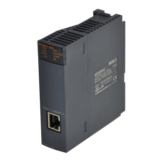
Ethernet interface module
Hide thumbs
Also See for Melsec Q Series:
- User manual (834 pages) ,
- Reference manual (674 pages) ,
- Programming manual (624 pages)
Table of Contents
Advertisement
Quick Links
Advertisement
Table of Contents

Related Manuals for Mitsubishi Electric Melsec Q Series


Summary of Contents for Mitsubishi Electric Melsec Q Series
-
Page 3: Safety Precautions
SAFETY PRECAUTIONS (Always read before starting use.) Before using this product, please read this manual introduced in this manual carefully and pay full attention to safety to handle the product correctly. The instructions given in this manual are concerned with this product. For the safety instructions of the programmable controller system, please read the user's manual for the CPU module to use. - Page 4 Precautions for using the MELSEC-Q series Ethernet interface module [Design Precautions] WARNING For the operating status of each station after a communication failure, refer to relevant manuals for the network. Erroneous outputs and malfunctions may lead to accidents. Not doing so can cause an accident due to false output or malfunction. ...
- Page 5 [Design Precautions] CAUTION Do not bundle the control wires and the communication cables with the main circuit and the power wires, and do not install them close to each other. They should be installed at least 100 mm (3.94 in.) away from each other. Failure to do so may generate noise that may cause malfunctions.
- Page 6 [Wiring Instructions] CAUTION Connectors for external connection must be crimped or pressed with the tool specified by the manufacturer, or must be correctly soldered. If the connection is incomplete, it may cause the module to short circuit, catch fire, or malfunction.
- Page 7 [Setup and Maintenance Precautions] CAUTION Never disassemble or modify the module. This may cause breakdowns, malfunctions, injuries or fire. Before mounting/dismounting the module, be sure to shut off all phases of external power supply used by the system. Failure to do so may cause module failure or malfunctions.
- Page 8 Precautions for using the MELSEC-L series Ethernet interface module [Design Precautions] WARNING For the operating status of each station after a communication failure, refer to relevant manuals for each network. Incorrect output or malfunction due to a communication failure may result in an accident.
- Page 9 [Design Precautions] CAUTION Do not install the control lines or communication cables together with the main circuit lines or power cables. Keep a distance of 100mm or more between them. Failure to do so may result in malfunction due to noise. ...
- Page 10 [Startup and Maintenance Precautions] WARNING Shut off the external power supply (all phases) used in the system before cleaning the module. Failure to do so may result in electric shock. [Startup and Maintenance Precautions] CAUTION Do not disassemble or modify the module. Doing so may cause failure, malfunction, injury, or a fire.
-
Page 11: Conditions Of Use For The Product
CONDITIONS OF USE FOR THE PRODUCT (1) Mitsubishi programmable controller ("the PRODUCT") shall be used in conditions; i) where any problem, fault or failure occurring in the PRODUCT, if any, shall not lead to any major or serious accident; and ii) where the backup and fail-safe function are systematically or automatically provided outside of the PRODUCT for the case of any problem, fault or failure occurring in the PRODUCT. -
Page 12: Revisions
REVISIONS The manual number is given on the bottom left of the back cover. Print Date Manual Number Revision Dec., 1999 SH(NA)-080010-A First edition Oct., 2000 SH(NA)-080010-B Reflect the contents of the function version B. Put Windows base software products together from Mitsubishi Programmable Controller MELSEC series to Mitsubishi integrated FA software MELSOFT series. - Page 13 This manual confers no industrial property rights or any rights of any other kind, nor does it confer any patent licenses. Mitsubishi Electric Corporation cannot be held responsible for any problems involving industrial property rights which may occur as a result of using the contents noted in this manual.
-
Page 14: Table Of Contents
INTRODUCTION Thank you for purchasing the Mitsubishi MELSEC-Q or -L series programmable controllers. This manual describes the functions and programming of the Ethernet interface module for Ethernet communications. Before using this product, please read this manual and the relevant manuals carefully and develop familiarity with the functions and performance of the MELSEC-Q or -L series programmable controller to handle the product correctly. - Page 15 2.9.1 News setting ............................. 2-32 2.9.2 Receiving a news e-mail ........................2-37 3 COMMUNICATIONS VIA OTHER NETWORKS 3- 1 to 3-22 3.1 CC-Link IE Controller Network, CC-Link IE Field Network, MELSECNET/H, MELSECNET/10 Relay Communication Function........................3- 1 3.2 Range of Accessible Other Station’s Programmable Controllers and Accessible Stations ....3- 2 3.2.1 Accessible range and stations ......................
- Page 16 6.7 J(P)/G(P).REQ (Remote RUN/STOP) ....................6-28 6.8 J(P)/G(P).REQ (Clock Data Read/Write) ....................6-34 6.9 JP/GP.SEND............................6-37 6.10 JP/GP.SREAD ............................6-46 6.11 JP/GP.SWRITE............................. 6-51 6.12 JP/GP.WRITE ............................6-56 6.13 J(P).ZNRD............................. 6-64 6.14 J(P).ZNWR............................6-68 APPENDIX App- 1 to App- 8 Appendix 1 Calculating the Setting Values of the Data Link Instructions (Control Data) .......App- 1 Appendix 1.1 Calculation formulas .......................App- 1 Appendix 1.2 Setting examples ......................App- 4 INDEX...
-
Page 17: Related Manuals
RELATED MANUALS The manuals related to this product are listed below. Please place an order as needed. Manual number Manual name (Model code) Q Corresponding Ethernet Interface Module User's Manual (Basic) Specifications of the Ethernet interface module, data communication procedures with external devices, SH-080009 (13JL88) line connections (open/close), fixed buffer communication, random access buffer communication, and... -
Page 18: The Manual's Use And Structure
The Manual's Use and Structure How to use this manual In this manual, explanations are given for each special function of the Ethernet modules (QJ71E71-100, QJ71E71-B5, QJ71E71-B2, and LJ71E71-100). Please use this manual using the following key items below as a reference. (1) To learn about an overview of the special functions •... - Page 19 Structure of this manual (1) Setting Parameters with a programming tool (a) By setting parameters with a programming tool, the sequence programs for communicating with external devices can be simplified in the Ethernet module. (b) In this manual, parameter settings using a programming tool are explained in detail for each item displayed on the setting screens.
- Page 20 (2) Setting screen of a programming tool This manual explains the parameter settings with a programming tool in the following format. The following illustration is for explanation purpose only, and should not be referred to as an actual documentation. A - 18 A - 18...
- Page 21 Depending on the function used, "(Address: )" may be indicated after some function names. This address indicates the buffer memory address of the Ethernet module in which the setting values from a programming tool are stored. For more details on the buffer memory, see the User's Manual (Basic). Open the network parameter screens as follows.
-
Page 22: About The Generic Terms And Abbreviations
About the Generic Terms and Abbreviations This manual uses the following generic terms and abbreviations to describe the QJ71E71-100, QJ71E71-B5, QJ71E71-B2, and LJ71E71-100 Ethernet interface modules, unless otherwise specified. Generic Term/Abbreviation Description ACPU A generic term for the AnNCPU, AnACPU, and AnUCPU A generic term for the A2ACPU, A2ACPU-S1, A2ACPUP21/R21, A2ACPUP21/R21- AnACPU S1, A3ACPU, and A3ACPUP21/R21... - Page 23 Generic Term/Abbreviation Description Programming tool A generic term for GX Developer and GX Works2 A generic term for a Basic model QCPU, High Performance model QCPU, Process CPU, QCPU Redundant CPU, and Universal model QCPU A generic term for the Q03UDVCPU, Q04UDVCPU, Q06UDVCPU, Q13UDVCPU, and QnUDVCPU Q26UDVCPU The abbreviation for the QJ71E71-100, QJ71E71-B5, and QJ71E71-B2 Ethernet interface...
-
Page 24: Overview
1 OVERVIEW MELSEC-Q/L 1 OVERVIEW This manual describes the special functions of an Ethernet interface module (hereinafter, abbreviated as Ethernet module). When applying the following program examples to the actual system, make sure to examine the applicability and confirm that it will not cause system control problems. This chapter describes an overview of the special functions that are available for the Ethernet module. - Page 25 1 OVERVIEW MELSEC-Q/L (2) Communicate with a programmable controller in another station via other networks (Details are explained in Chapter 3) This function enables accessing other stations via multiple networks in the network system shown below. This function is used for multiple relays through a network in which the Ethernet and CC-Link IE Controller Network, CC-Link IE Field Network, MELSECNET/H, MELSECNET/10 network systems coexist as well as through a network in which multiple Ethernet network systems are connected.
- Page 26 1 OVERVIEW MELSEC-Q/L (3) Perform data communication between programmable controller CPUs (Details are explained in Chapter 4) This function sends and receives data to/from another station's programmable controller CPU via the Ethernet using the data link instructions (SEND/RECV/READ/WRITE/REQ/ZNRD/ZNWR). ( 1) It also sends and receives data to/from a programmable controller CPU in another station via Ethernet and other networks.
-
Page 27: Additional Functions In Function Version B Or Later
1 OVERVIEW MELSEC-Q/L 1.2 Additional Functions in Function Version B or Later The following table lists the functions added to Q series Ethernet modules of function version B or later. POINT (1) The added/changed functions shown in this section includes the functions added in the first products or later of function version B and function version D. - Page 28 1 OVERVIEW MELSEC-Q/L (2) Function added for function version D Reference Function Overview section Sending character strings in the e-mail’s When using The programmable controller CPU monitoring function allows main text by the the e-mail transmission of character string information stored in word Chapter 2 programmable function...
-
Page 29: Using The E-Mail Function
2 USING THE E-MAIL FUNCTION MELSEC-Q/L 2 USING THE E-MAIL FUNCTION 2.1 E-mail Function The e-mail function sends and receives CPU information (programmable controller CPU status and device values) to/from PCs or programmable controller CPUs in remote locations via the Internet. The following two methods are available to send/receive e-mail using this function. - Page 30 2 USING THE E-MAIL FUNCTION MELSEC-Q/L (2) Data conversion method used by the Ethernet module The following shows the data conversion method used by the Ethernet module. When sending e-mails When receiving e-mails Mail Mail Programmable Programmable server server controller CPU controller CPU (Does not decode) Subject...
-
Page 31: Sending E-Mail Using The Programmable Controller Cpu Monitor Function
2 USING THE E-MAIL FUNCTION MELSEC-Q/L 2.1.2 Sending e-mail using the programmable controller CPU monitor function (1) Monitor function of the programmable controller CPU The monitor function of the programmable controller CPU is used to regularly monitor the status of the programmable controller CPU and device values, and send e-mail to the designated external device when they match with the notification conditions (programmable controller CPU status and device values) set by the user. - Page 32 2 USING THE E-MAIL FUNCTION MELSEC-Q/L (3) Flow of the e-mail The diagram shown below illustrates the flow of e-mails from the local station's Ethernet module to the external device after the monitor values match with the news conditions. Programmable Ethernet module controller CPU Read monitoring...
-
Page 33: Configuration And Environment Of The Applicable System
2 USING THE E-MAIL FUNCTION MELSEC-Q/L 2.2 Configuration and Environment of the Applicable System This section explains the environment and system configuration for using the e-mail function from the Ethernet module. Internet (Public line) Internet service provider Internet service provider Public line Router Router... -
Page 34: Precautions For Using The E-Mail Function
2 USING THE E-MAIL FUNCTION MELSEC-Q/L 2.3 Precautions for Using the E-mail Function The following explains precautions when using the e-mail function of the Ethernet module. (1) Precautions regarding the system (a) Design the system so that the entire system operates normally at all times when sending/receiving e-mails to/from a running system and controlling the programmable controller. - Page 35 2 USING THE E-MAIL FUNCTION MELSEC-Q/L (f) When communication errors of e-mails cannot be checked by a dedicated instruction, check the error codes stored in the mail send/reception error log area of the buffer memory. (g) If e-mails cannot be received, try one of the following. Execute the MRECV instruction once.
-
Page 36: E-Mail Specifications
2 USING THE E-MAIL FUNCTION MELSEC-Q/L 2.4 E-mail Specifications The following table lists the specifications of the e-mail function. Item Specification Attached file 6 k words Data size Main text 960 words When sending: Sends either a file as attachment or main text (select one). Data transfer method When receiving: Received a file as attachment. -
Page 37: Processing Procedure Of The E-Mail Function
2 USING THE E-MAIL FUNCTION MELSEC-Q/L 2.5 Processing Procedure of the E-mail Function The following flowchart illustrates the procedure that is required before sending and receiving e-mails: Start When DNS is not used When DNS is used See Section 2.6 (1) Register the DNS server See Section 2.6 (2) Register the mail address of the local station's Ethernet module... -
Page 38: E-Mail Setting Using A Programming Tool
2 USING THE E-MAIL FUNCTION MELSEC-Q/L 2.6 E-mail Setting Using a Programming Tool This section describes the settings required to send and receive e-mails using a programming tool. (1) DNS setting [Purpose of setting] Specify the IP address of the DNS server when setting the mail server name using the domain name by the e-mail setting (see (2)). - Page 39 2 USING THE E-MAIL FUNCTION MELSEC-Q/L Initial settings Item name Description of setting Setting range/options TCP ULP Timer Set the time of packet existence at TCP data send. 2 to 32767 Set the interval for checking the receive enabled TCP Zero Window Timer 2 to 32767 status.
- Page 40 2 USING THE E-MAIL FUNCTION MELSEC-Q/L (2) E-mail setting [Purpose of setting] Perform the setting to use the e-mail function. [Start procedure] Network parameter setting screen E-mail Setting [Setting screen] [Setting item] Item name Description of setting item Setting range/option Password Set the password to the mail server Up to 63 characters...
- Page 41 2 USING THE E-MAIL FUNCTION MELSEC-Q/L (a) General settings Designate the mail setting values that have been registered with the Internet service provider of the local station's Ethernet module or the mail registration information designated by the system administrator. 1) Password: Designate the mail password of the local station's Ethernet module.
- Page 42 2 USING THE E-MAIL FUNCTION MELSEC-Q/L (3) Send mail address setting [Purpose of setting] Register the e-mail address of the external devices where e-mail is to be sent. [Start procedure] E-mail setting screen Send Mail Address Setting [Setting screen] [Setting item] Item name Description of setting...
-
Page 43: Sending/Receiving E-Mail (Attached Files) By The Programmable Controller Cpu
2 USING THE E-MAIL FUNCTION MELSEC-Q/L 2.7 Sending/Receiving E-mail (Attached Files) by the Programmable Controller CPU This section explains how to send and receive attached files of e-mail using the dedicated instructions (MSEND/MRECV) available for the Ethernet module. 2.7.1 When sending data as an attached file The following explains the MSEND instruction and program for sending e-mail. - Page 44 2 USING THE E-MAIL FUNCTION MELSEC-Q/L (1) Send using the sequence program The following explains how an e-mail is sent using the sequence program. See Chapter 6 MSEND for detail. Direction Create control data at D20 and on Create send data at D200 and on Send the e-mail ZP.MSEND "U0"...
- Page 45 2 USING THE E-MAIL FUNCTION MELSEC-Q/L (3) Sample program The following shows a sample program for sending e-mails by the programmable controller CPU. Perform e-mail send processing using the send command (X20). The contents of the send data are shown in (4). When I/O signals of the Ethernet module are X/Y00 to X/Y1F.
- Page 46 2 USING THE E-MAIL FUNCTION MELSEC-Q/L 1 The following shows the transmission format of the attached file designated in the control data of the MSEND instruction. For how to select the binary format, ASCII format, and CSV format, see Section 6.3.
- Page 47 2 USING THE E-MAIL FUNCTION MELSEC-Q/L (4) Receiving by a personal computer The following explains how a PC/UNIX receives e-mails sent from the Ethernet module. After setting the environment where the Internet is accessible with a mail user agent, receive e-mails on the receiving message screen as follows. (Example) The following shows an example of the reception of e-mail sent using the MSEND instruction (see (3)).
-
Page 48: When Receiving Data In The Attached File
2 USING THE E-MAIL FUNCTION MELSEC-Q/L 2.7.2 When receiving data in the attached file This section explains the MRECV instruction and a program to receive e-mails sent from external devices. The MRECV instruction reads the attached file received. ZP.MRECV "Un" (D1) (D2) Mail server... - Page 49 2 USING THE E-MAIL FUNCTION MELSEC-Q/L 1 In the mail information storage area, the following information related to the receive mail is stored in the corresponding bits. Mail information storage area b14 to b5 address 2682 (9858) 1) Indicates whether the information (maximum of 128 words) in the From head address storage area is valid (1) or invalid (0).
- Page 50 2 USING THE E-MAIL FUNCTION MELSEC-Q/L (1) Reception using the sequence program The following explains the designation method in a sequence program. For details, see Section 6.2. Instruction Un\G9858.F Create control data at D0 and on E-mail is read if there is recieve mail in Ethernet module Read the receive mail information...
- Page 51 2 USING THE E-MAIL FUNCTION MELSEC-Q/L 1) Start up the local station programmable controller. The parameters for the e-mail function are stored in the Ethernet module. 2) Check whether or not any received e-mails are stored on the mail server. If any receive mail has been stored, the receive mail information is stored in the buffer memory.
- Page 52 2 USING THE E-MAIL FUNCTION MELSEC-Q/L (3) Sample program The following is a sample program for receiving e-mail by a programmable controller CPU. It performs reception processing of e-mail using the receive command (X21). When I/O signals of the Ethernet module are X/Y00 to X/Y1F. Designate to make inquiry to the server.
- Page 53 2 USING THE E-MAIL FUNCTION MELSEC-Q/L (4) Sending an e-mail from a personal computer This section explains how to send e-mails from a PC/UNIX to the Ethernet module. After setting the environment where the Internet is accessible with a mail user agent, create and send an e-mail on the sending message creation screen as follows.
-
Page 54: Contents Of The Attached Files
2 USING THE E-MAIL FUNCTION MELSEC-Q/L 2.7.3 Contents of the attached files The following explains the contents of the attached file data. The data format of the attached file is ASCII code (ASCII format, CSV format) or binary code (binary format). The following example shows the transmission contents for each data format (binary/ASCII/CSV) when the Ethernet module sends the data register value as an attached file. - Page 55 2 USING THE E-MAIL FUNCTION MELSEC-Q/L (2) Data configuration in CSV format Data in CSV format can be used as control data for the cell units in Excel, etc. Data in CSV format handled by the Ethernet module is the data expressed as follows.
-
Page 56: Sending E-Mail (Main Text) By The Programmable Controller Cpu
2 USING THE E-MAIL FUNCTION MELSEC-Q/L 2.8 Sending E-mail (Main Text) by the Programmable Controller CPU This section explains how to send the main text of e-mail using the dedicated MSEND instruction available for the Ethernet module. 2.8.1 When sending data as main text of e-mail The following explains the MSEND instruction and program for sending e-mail. - Page 57 2 USING THE E-MAIL FUNCTION MELSEC-Q/L (1) Send using the sequence program The following explains how an e-mail is sent using a sequence program. For details, see Section 6.3. Direction Create control data at D20 and on Create send data at D200 and on Send the e-mail ZP.MSEND "U0"...
- Page 58 2 USING THE E-MAIL FUNCTION MELSEC-Q/L Sample program The following shows a sample program for sending e-mail by the programmable controller CPU. Perform e-mail transmission processing the send command (X20). The contents of the send data are shown in (4). When I/O signals of the Ethernet module are X/Y00 to X/Y1F Designate main text as the send data format.
- Page 59 2 USING THE E-MAIL FUNCTION MELSEC-Q/L (4) Receiving by a personal computer The following explains how a PC/UNIX/portable terminal receives e-mail sent from the Ethernet module. After setting the environment where the Internet is accessible with a mail user agent, receive an e-mail on the receiving message screen as follows. (Example) The following shows an example of the reception of e-mail sent using the MSEND instruction (see (3)).
-
Page 60: Sending E-Mails Using The Programmable Controller Cpu Monitoring Function
2 USING THE E-MAIL FUNCTION MELSEC-Q/L 2.9 Sending E-mails Using the Programmable Controller CPU Monitoring Function When the monitoring information read from the Q/LCPU matches with the news conditions set by the user, the Ethernet module sends an e-mail to the external device. 2.9.1 News setting [Purpose of setting] The monitoring conditions (notification conditions) of the programmable controller CPU... - Page 61 2 USING THE E-MAIL FUNCTION MELSEC-Q/L News settings Notification condition Item name Description of setting Setting range/option CPU status Device monitoring ( 1) monitoring • No Setting • Normal STOP • Serious/Fatal Error • Warning STOP Condition for PLC Select the monitoring condition for the (Moderate error STOP) Inspection •...
- Page 62 2 USING THE E-MAIL FUNCTION MELSEC-Q/L (2) Send method Select the send method of the device monitoring results. Item Explanation Send Attached File Sends data as an attached file in the file format designated in (3). Sends data as the main text of e-mail in ASCII code format. Send Text Mail It is not necessary to designate items (3) and (4) when this setting is used.
- Page 63 2 USING THE E-MAIL FUNCTION MELSEC-Q/L (7) Condition device Designate the device to be monitored. POINT (1) A maximum of 16 devices can be monitored. (2) It is possible to designate devices that can be accessed for communication using the MC protocol directly as condition devices (see the Reference Manual). In this case, Timer, Retentive timer and Counter should be designated by T, ST, or C.
- Page 64 2 USING THE E-MAIL FUNCTION MELSEC-Q/L (9) Monitoring value Designate the comparison value of the condition of comparison given in (8) above. (10) News data storage device The condition device that stores the news data is set when the news condition is satisfied.
-
Page 65: Receiving A News E-Mail
2 USING THE E-MAIL FUNCTION MELSEC-Q/L 2.9.2 Receiving a news e-mail The designated external device side can open the news e-mail from the Ethernet module in the same way as opening a mail received from the programmable controller CPU. (1) When monitoring the CPU status When the result of the CPU status monitoring matches the monitoring condition, the Subject will be sent. - Page 66 2 USING THE E-MAIL FUNCTION MELSEC-Q/L (2) When monitoring a device When any of the results of the device monitoring matches the monitoring condition among the devices having the conditions designated on the news setting screen, the Subject and attached file, or the Subject and main text will be sent.
- Page 67 2 USING THE E-MAIL FUNCTION MELSEC-Q/L The contents of the data recorded are as follows. 1) When sending data as an attached file • If the data format is binary, values are recorded from the lower byte (L) side. • If the data format is ASCII, target values are converted to 4-digit hexadecimal ASCII codes and recorded from the higher byte (H) side of the values.
- Page 68 2 USING THE E-MAIL FUNCTION MELSEC-Q/L 2) When sending data as main text <When data format is CSV> • Target data values are converted to 4-digit hexadecimal ASCII codes and recorded from the higher byte (H) side of the values. •...
- Page 69 2 USING THE E-MAIL FUNCTION MELSEC-Q/L <When data format is character strings (binary)> • The device name and display device No. are recorded for each setting device. • When “Condition for inspection” is set to “No conditional settings (character string send)”, “Notification data storage device” records the data of specified notification points starting from the low byte (L) of the specified value.
-
Page 70: Communications Via Other Networks
3 COMMUNICATIONS VIA OTHER NETWORKS MELSEC-Q/L 3 COMMUNICATIONS VIA OTHER NETWORKS An Ethernet module can access other stations from an external device or a Q/LCPU in a station where an Ethernet module is connected via Ethernet and the following networks: •... -
Page 71: Range Of Accessible Other Station's Programmable Controllers And Accessible Stations
3 COMMUNICATIONS VIA OTHER NETWORKS MELSEC-Q/L 3.2 Range of Accessible Other Station’s Programmable Controllers and Accessible Stations The accessible range and the stations when performing the other station access via Ethernet module using the CC-Link IE Controller Network, CC-Link IE Field Network, MELSECNET/H, MELSECNET/10 relay communication function is described. - Page 72 3 COMMUNICATIONS VIA OTHER NETWORKS MELSEC-Q/L (2) Accessible stations (communication request destination stations) and relay stations (communication relay stations) This relay communication function allows communication with programmable controllers of other stations if the communication destination programmable controllers (communication request destination stations) and all the relay stations to the communication destination stations (communication relay stations) are configured with the modules listed below.
- Page 73 3 COMMUNICATIONS VIA OTHER NETWORKS MELSEC-Q/L (b) Modules that can act as relays between networks (communication relay stations) Model name CC-Link IE Controller Network QJ71GP21-SX, QJ71GP21S-SX CC-Link IE Field Network QJ71GF11-T2, LJ71GF11-T2 QJ71LP21, QJ71LP21-25, QJ71LP21S-25, QJ71LP21GE, QJ71BR11, QJ71NT11B MELSECNET/H (MELSECNET/H mode) QJ71LP21, QJ71LP21-25, QJ71LP21S-25, QJ71LP21GE, QJ71BR11 (MELSECNET/10 mode) MELSECNET/10...
-
Page 74: Settings For Accessing Other Stations
3 COMMUNICATIONS VIA OTHER NETWORKS MELSEC-Q/L 3.3 Settings for Accessing Other Stations This section explains the parameters and setting items that need to be set with a programming tool to access other stations via the Ethernet using the CC-Link IE Controller Network, CC-Link IE Field Network, MELSECNET/H, MELSECNET/10 relay communication function. -
Page 75: Setting The Station No. <-> Ip Information
3 COMMUNICATIONS VIA OTHER NETWORKS MELSEC-Q/L 3.3.1 Setting the Station No. <-> IP information This section explains the Station No. <-> IP information settings that are required to access other stations via the Ethernet module using the CC-Link IE Controller Network, CC-Link IE Field Network, MELSECNET/H, MELSECNET/10 relay communication function. - Page 76 3 COMMUNICATIONS VIA OTHER NETWORKS MELSEC-Q/L (1) Station No. <-> IP information system (conversion method) (address: ... b7, b6) (a) There are four kinds of Station No. <-> IP information methods as shown below. (b) Select one of them according to Section 3.3.2 and make sure to set the values on this screen using the method selected.
- Page 77 3 COMMUNICATIONS VIA OTHER NETWORKS MELSEC-Q/L POINT (1) Communication between the Ethernet module and Q/LCPU is performed according to the network No. and station No., and communication between two Ethernet modules are performed according to the IP address and UDP port number.
-
Page 78: Convert Format Between The Network No./Station Number And Ip Address/Port Number
3 COMMUNICATIONS VIA OTHER NETWORKS MELSEC-Q/L 3.3.2 Convert format between the Network No./station number and IP address/port number The process overview of the conversion method set by the Station No. <-> IP information screen for performing the other station access via Ethernet module using the CC-Link IE Controller Network, CC-Link IE Field Network, MELSECNET/H, MELSECNET/10 relay communication function is explained. - Page 79 3 COMMUNICATIONS VIA OTHER NETWORKS MELSEC-Q/L (2) IP address computation system (a) Overview of the IP address computation system During calculation, the IP address of the partner station is obtained from the calculation equation below according to the Network No. and station number, and the UDP port number predefined for the Ethernet module system is used as the UDP port number of the destination.
- Page 80 3 COMMUNICATIONS VIA OTHER NETWORKS MELSEC-Q/L (For class B) • When the local station IP Address is 8438FA0A • When the Net Mask Pattern for routing other networks is FFFF0000 • When the destination Network No. is 03 and station number is 05 Local station IP Address Net Mask Pattern Logical product...
- Page 81 3 COMMUNICATIONS VIA OTHER NETWORKS MELSEC-Q/L (3) Table exchange system (a) Overview of the table exchange system 1) This method uses the Network No., station number, and IP address set in the conversion table of the Station No. <-> IP information, and uses the UDP port number predefined for the Ethernet module system as the UDP port number of the destination.
- Page 82 3 COMMUNICATIONS VIA OTHER NETWORKS MELSEC-Q/L (Setting example) 1) Communication request source station Network No. Station No. : 11 : (192. 0. 1. 11) IP Address Ethernet (Network No.1) 2) Communication relay 3) Communication relay receiving station sending station Network No. Network No.
- Page 83 3 COMMUNICATIONS VIA OTHER NETWORKS MELSEC-Q/L (4) Use-together system (a) Overview of the Use-together system 1) This method uses both the IP address computation system and the table exchange system. 2) Select this method to access other stations with the same Network No., accessing other stations in other networks or accessing Ethernet with different Network No., and relaying from other networks to the Ethernet network system.
-
Page 84: Routing Parameter Settings
3 COMMUNICATIONS VIA OTHER NETWORKS MELSEC-Q/L 3.3.3 Routing parameter settings The routing parameters contain information of the Ethernet modules passed through when accessing other stations. This section explains the routing parameters that must be set in order to access other stations via the Ethernet module using the CC-Link IE Controller Network, CC-Link IE Field Network, MELSECNET/H, MELSECNET/10 relay communication function. - Page 85 3 COMMUNICATIONS VIA OTHER NETWORKS MELSEC-Q/L (1) Target Network No. Designate the Network No. of Ethernet or other networks to which the communication request destination station or the communication request source station is connected when sending a communication request message or a response message, respectively.
- Page 86 3 COMMUNICATIONS VIA OTHER NETWORKS MELSEC-Q/L (The meanings of the symbols used for the stations shown in the diagram) • Network system (CC-Link IE Controller Network, CC-Link IE Field Network, MELSECNET/H, MELSECNET/10) (Network number 1, control station, station number 1) Station number Control station/normal station Mp……Control station...
- Page 87 3 COMMUNICATIONS VIA OTHER NETWORKS MELSEC-Q/L (4) Using the example of a system shown below, the accessible stations and the stations that require parameter settings when an external device or Q/LCPU access other stations are explained. Stations that require the setting of the "setting the Ethernet router relay parameter"...
- Page 88 3 COMMUNICATIONS VIA OTHER NETWORKS MELSEC-Q/L (1) When performing a remote access from 1) to 2) Station that does ( )/does not ( ) require setting Setting item Network parameter Routing information setting Setting the Ethernet Station No. <-> IP information Setting the Ethernet router relay parameter (2) When performing a remote access from 1) to 3)
- Page 89 3 COMMUNICATIONS VIA OTHER NETWORKS MELSEC-Q/L (5) When performing a remote access from 7) to 1) Station that does ( )/does not ( ) require setting Setting item Network parameter Routing information setting Setting the Ethernet Station No. <-> IP information Setting the Ethernet router relay parameter (6) When performing a remote access from 7) to 3)
-
Page 90: Procedure For Accessing Other Stations
3 COMMUNICATIONS VIA OTHER NETWORKS MELSEC-Q/L 3.4 Procedure for Accessing Other Stations This section explains the procedure for accessing other stations via the Ethernet using the CC-Link IE Controller Network, CC-Link IE Field Network, MELSECNET/H, MELSECNET/10 relay communication function as well as the required processing. (1) Setting the parameters The parameters shown in Section 3.3 must be set using a programming tool. - Page 91 3 COMMUNICATIONS VIA OTHER NETWORKS MELSEC-Q/L POINT See the manual for each network module for the interlock signals and the send/receive processing and processing time of the link data when performing data communication with Q/LCPUs of other stations via other networks. 3 - 22 3 - 22...
-
Page 92: When The Q/Lcpu Accesses The Programmable Controller Of Another Station Using The Data Link Instruction
4 WHEN THE Q/LCPU ACCESSES THE PROGRAMMABLE CONTROLLER OF ANOTHER STATION USING THE DATA LINK INSTRUCTION MELSEC-Q/L 4 WHEN THE Q/LCPU ACCESSES THE PROGRAMMABLE CONTROLLER OF ANOTHER STATION USING THE DATA LINK INSTRUCTION With the CC-Link IE Controller Network, CC-Link IE Field Network, MELSECNET/H, MELSECNET/10 relay communication function, the Q/LCPU can perform data communication with the programmable controller CPUs of other stations as follows using the data link instructions. -
Page 93: Precautions For Accessing Other Stations
4 WHEN THE Q/LCPU ACCESSES THE PROGRAMMABLE CONTROLLER OF ANOTHER STATION USING THE DATA LINK INSTRUCTION MELSEC-Q/L 4.2 Precautions for Accessing Other Stations The following describes precautions when accessing other stations via the Ethernet module using the data link instructions. (1) Executing multiple instructions at one time (common to the data link instructions) (a) When simultaneously accessing multiple other stations from the own station,... - Page 94 4 WHEN THE Q/LCPU ACCESSES THE PROGRAMMABLE CONTROLLER OF ANOTHER STATION USING THE DATA LINK INSTRUCTION MELSEC-Q/L (2) Setting the arrival monitoring time of the control data storage device When the setting unit of arrival monitoring time is "1s", set a value greater than or equal to the TCP resend timer value set in the initial processing parameter for the arrival monitoring time designation area of the control data storage device.
- Page 95 4 WHEN THE Q/LCPU ACCESSES THE PROGRAMMABLE CONTROLLER OF ANOTHER STATION USING THE DATA LINK INSTRUCTION MELSEC-Q/L (5) Channels used by the ZNRD and ZNWR instructions The ZNRD and ZNWR instructions for Ethernet modules are executed using the following channels of the target Ethernet module. •...
-
Page 96: Using The Data Link Instructions
4 WHEN THE Q/LCPU ACCESSES THE PROGRAMMABLE CONTROLLER OF ANOTHER STATION USING THE DATA LINK INSTRUCTION MELSEC-Q/L 4.3 Using the Data Link Instructions This section explains how to use the data link instructions when accessing other stations via the Ethernet module. (1) SEND instruction 1) When performing simultaneous other station accesses from multiple communication request source stations to the same communication... - Page 97 4 WHEN THE Q/LCPU ACCESSES THE PROGRAMMABLE CONTROLLER OF ANOTHER STATION USING THE DATA LINK INSTRUCTION MELSEC-Q/L (Example) IP address when the command is sent (for class B) Bit location 31 30 29 FFFF Class Network address Host address Read-dump the received commands not related to the local station on the external device.
- Page 98 4 WHEN THE Q/LCPU ACCESSES THE PROGRAMMABLE CONTROLLER OF ANOTHER STATION USING THE DATA LINK INSTRUCTION MELSEC-Q/L (Example) READ instruction execution timing 1) Communication timing when the READ instruction completed successfully (when resend is not performed) Programmable Programmable controller CPU (Local station) (another station) controller CPU...
-
Page 99: Data Link Instructions
4 WHEN THE Q/LCPU ACCESSES THE PROGRAMMABLE CONTROLLER OF ANOTHER STATION USING THE DATA LINK INSTRUCTION MELSEC-Q/L 4.4 Data Link Instructions This section explains the overview of the data send/receive in each data link instruction when accessing via Ethernet Module. Channels 1 to 8 of the Ethernet module and network module in the figure of the following table are the OS areas that store send/receive data with each data link instruction. - Page 100 4 WHEN THE Q/LCPU ACCESSES THE PROGRAMMABLE CONTROLLER OF ANOTHER STATION USING THE DATA LINK INSTRUCTION MELSEC-Q/L Instruction execution Target station station (Local station) Details Instruction Station type Station type Target station type Writes data to another station's word device. Ethernet Ethernet (With SWRITE, the completion device on...
- Page 101 4 WHEN THE Q/LCPU ACCESSES THE PROGRAMMABLE CONTROLLER OF ANOTHER STATION USING THE DATA LINK INSTRUCTION MELSEC-Q/L Instruction execution Target station station (Local station) Details Instruction Station type Station type Target station type Reads data from another station's word Ethernet Ethernet device.
- Page 102 4 WHEN THE Q/LCPU ACCESSES THE PROGRAMMABLE CONTROLLER OF ANOTHER STATION USING THE DATA LINK INSTRUCTION MELSEC-Q/L POINT (1) The CC-Link IE Controller Network, CC-Link IE Field Network, MELSECNET/H, MELSECNET/10 network No., group No., and station No., for the Ethernet module in the data link instruction setting data, designate the network No., group No., and station No., assigned to the Ethernet module by the "Setting the number of Ethernet/CC IE/MELSECNET cards"...
-
Page 103: Data Sending/Receiving
4 WHEN THE Q/LCPU ACCESSES THE PROGRAMMABLE CONTROLLER OF ANOTHER STATION USING THE DATA LINK INSTRUCTION MELSEC-Q/L 4.5 Data Sending/Receiving This section explains the arbitrary data sending/receiving function, instruction format and programs using the data send/receive instructions (SEND, RECV and RECVS instructions). -
Page 104: Data Sending/Receiving For Receive With The Main Program (Send/Recv)
4 WHEN THE Q/LCPU ACCESSES THE PROGRAMMABLE CONTROLLER OF ANOTHER STATION USING THE DATA LINK INSTRUCTION MELSEC-Q/L 4.5.1 Data sending/receiving for receive with the main program (SEND/RECV) This section explains the format and program examples of the SEND and RECV instructions that are used to send/receive data between the programmable controller CPUs. - Page 105 4 WHEN THE Q/LCPU ACCESSES THE PROGRAMMABLE CONTROLLER OF ANOTHER STATION USING THE DATA LINK INSTRUCTION MELSEC-Q/L (b) RECV instruction (for receive by the main program) [Network number designation] Receive command JP: Exection JP.RECV (D1) (D2) during startup [Network module/Ethernet module start I/O signal designation] Receive command GP: Execution GP.RECV...
- Page 106 4 WHEN THE Q/LCPU ACCESSES THE PROGRAMMABLE CONTROLLER OF ANOTHER STATION USING THE DATA LINK INSTRUCTION MELSEC-Q/L (2) Instruction execution timing (for receive processing by the main program) (a) When normal completion SEND (With arrival confirmation) Sequence scan Send command Sending side programmable controller CPU...
- Page 107 4 WHEN THE Q/LCPU ACCESSES THE PROGRAMMABLE CONTROLLER OF ANOTHER STATION USING THE DATA LINK INSTRUCTION MELSEC-Q/L (b) When abnormal completion 1) SEND instruction SEND Sequence scan Send command Sending side programmable Send completion device (Device specified with (D)) controller CPU Send completion device ((D)+1 device ) 1 scan...
- Page 108 4 WHEN THE Q/LCPU ACCESSES THE PROGRAMMABLE CONTROLLER OF ANOTHER STATION USING THE DATA LINK INSTRUCTION MELSEC-Q/L (3) Program example Station 3 uses channel 3 with an SEND instruction, and sends data to station 15 using channel 5. When data is received at station 15, data is read from channel 5. Programmable Programmable controller CPU...
- Page 109 4 WHEN THE Q/LCPU ACCESSES THE PROGRAMMABLE CONTROLLER OF ANOTHER STATION USING THE DATA LINK INSTRUCTION MELSEC-Q/L (b) Station 15 program (RECV instruction) When I/O signals of the Ethernet module are X/Y00 to X/Y1F Clock data setting required Local station storage channel Arrival monitoring time (20 s) X19: Initial normal completion signal Processing program when receive completion...
-
Page 110: Data Sending/Receiving For Receive With An Interrupt Program (Send/Recvs)
4 WHEN THE Q/LCPU ACCESSES THE PROGRAMMABLE CONTROLLER OF ANOTHER STATION USING THE DATA LINK INSTRUCTION MELSEC-Q/L 4.5.2 Data sending/receiving for receive with an interrupt program (SEND/RECVS) This section explains the format and program examples of the RECVS instruction for receive when sending/receiving data between the programmable controller CPUs. - Page 111 4 WHEN THE Q/LCPU ACCESSES THE PROGRAMMABLE CONTROLLER OF ANOTHER STATION USING THE DATA LINK INSTRUCTION MELSEC-Q/L (2) Execution timing of the instruction (When executing reception processing by an interrupt program) (a) When normal completion SEND (With arrival confirmation) Sequence scan Send command Sending side programmable...
- Page 112 4 WHEN THE Q/LCPU ACCESSES THE PROGRAMMABLE CONTROLLER OF ANOTHER STATION USING THE DATA LINK INSTRUCTION MELSEC-Q/L (b) When abnormal completion 1) SEND instruction SEND Sequence scan Send command Sending side Send completion device programmable (Device specified with (D)) controller CPU Send completion device ((D)+1 device) 1 scan...
- Page 113 4 WHEN THE Q/LCPU ACCESSES THE PROGRAMMABLE CONTROLLER OF ANOTHER STATION USING THE DATA LINK INSTRUCTION MELSEC-Q/L (3) Program examples Station 3 uses channel 3 with an SEND instruction and sends data to station 15 using channel 5. When data is received at station 15, data is read from channel 5. Programmable Programmable controller CPU...
-
Page 114: Reading/Writing Word Devices Of Other Stations (Read/Write)
4 WHEN THE Q/LCPU ACCESSES THE PROGRAMMABLE CONTROLLER OF ANOTHER STATION USING THE DATA LINK INSTRUCTION MELSEC-Q/L 4.6 Reading/Writing Word Devices of Other Stations (READ/WRITE) This section explains the format and program examples of the READ/WRITE instructions that are used to read and write data of word devices of other stations. For details, see Sections 6.4, and 6.10 to 6.12. - Page 115 4 WHEN THE Q/LCPU ACCESSES THE PROGRAMMABLE CONTROLLER OF ANOTHER STATION USING THE DATA LINK INSTRUCTION MELSEC-Q/L Setting details Setting range 1 to 239: Network number 254: Network designated in a Local station network number valid module for other station access.
- Page 116 4 WHEN THE Q/LCPU ACCESSES THE PROGRAMMABLE CONTROLLER OF ANOTHER STATION USING THE DATA LINK INSTRUCTION MELSEC-Q/L Setting details Setting range 1 to 239: Network number 254: Network designated in Local station network number a valid module for other station access. Start I/O signal of the local station network module/Ethernet module.
- Page 117 4 WHEN THE Q/LCPU ACCESSES THE PROGRAMMABLE CONTROLLER OF ANOTHER STATION USING THE DATA LINK INSTRUCTION MELSEC-Q/L (2) Instruction execution timing (a) When normal completion 1) READ instruction, SREAD instruction READ Sequence scan Read command Local station programmable Read completion device controller CPU (Device specified with (D2)) 1 scan...
- Page 118 4 WHEN THE Q/LCPU ACCESSES THE PROGRAMMABLE CONTROLLER OF ANOTHER STATION USING THE DATA LINK INSTRUCTION MELSEC-Q/L 2) WRITE instruction, SWRITE instruction WRITE Sequence scan Write command Local station programmable Write completion device controller CPU (Device specified with (D2)) 1 scan Write completion device ((D2)+1 device) Write data storage device...
- Page 119 4 WHEN THE Q/LCPU ACCESSES THE PROGRAMMABLE CONTROLLER OF ANOTHER STATION USING THE DATA LINK INSTRUCTION MELSEC-Q/L (b) When abnormal completion 1) READ instruction, SREAD instruction READ Sequence scan Read command Local station programmable Read completion device controller CPU (Device specified with (D2)) Read completion device ((D2)+1 device) 1 scan...
- Page 120 4 WHEN THE Q/LCPU ACCESSES THE PROGRAMMABLE CONTROLLER OF ANOTHER STATION USING THE DATA LINK INSTRUCTION MELSEC-Q/L (3) Program example Read data from D10 to 14 of station 4 to D200 to 204 of station 1. Write the data stored in D300 to 303 of station 2 to D50 to 53 of station 3. Station 1 Station 2 Programmable...
- Page 121 4 WHEN THE Q/LCPU ACCESSES THE PROGRAMMABLE CONTROLLER OF ANOTHER STATION USING THE DATA LINK INSTRUCTION MELSEC-Q/L (b) Station 2 programs (SWRITE instruction) When I/O signals of Ethernet module are X/Y40 to X/Y5F With arrival confirmation/clock data setting required. Control data setting command...
-
Page 122: Reading/Writing Word Devices Of Other Stations (Znrd/Znwr)
4 WHEN THE Q/LCPU ACCESSES THE PROGRAMMABLE CONTROLLER OF ANOTHER STATION USING THE DATA LINK INSTRUCTION MELSEC-Q/L 4.7 Reading/Writing Word Devices of Other Stations (ZNRD/ZNWR) This section explains the format and program examples of the ZNRD/ZNWR instructions that are used to read and write data of word devices of other station. For details, see Sections 6.13 and 6.14. - Page 123 4 WHEN THE Q/LCPU ACCESSES THE PROGRAMMABLE CONTROLLER OF ANOTHER STATION USING THE DATA LINK INSTRUCTION MELSEC-Q/L (b) ZNWR instruction [Network number designation] Write command J: Execution J.ZNWR (D1) (D2) during ON Write command J: Execution JP.ZNWR (D1) (D2) during startup Setting details Setting range Target station network number...
- Page 124 4 WHEN THE Q/LCPU ACCESSES THE PROGRAMMABLE CONTROLLER OF ANOTHER STATION USING THE DATA LINK INSTRUCTION MELSEC-Q/L (2) Instruction execution timing (a) When normal completion 1) ZNRD instruction ZNRD Sequence scan Read command Local station programmable Read completion controller CPU (Device specified with (D2)) 1 scan Read completion device...
- Page 125 4 WHEN THE Q/LCPU ACCESSES THE PROGRAMMABLE CONTROLLER OF ANOTHER STATION USING THE DATA LINK INSTRUCTION MELSEC-Q/L 2) ZNWR instruction ZNWR Sequence scan Write command Local station programmable Write completion device controller CPU (Device specified with (D2)) 1 scan Write completion device ((D2)+1 device) Write data storage device 3000...
- Page 126 4 WHEN THE Q/LCPU ACCESSES THE PROGRAMMABLE CONTROLLER OF ANOTHER STATION USING THE DATA LINK INSTRUCTION MELSEC-Q/L (b) When abnormal completion 1) ZNRD instruction ZNRD Sequence scan Read command Local station programmable Read completion device controller CPU (Device specified with (D2)) Read completion device ((D2)+1 device) 1 scan...
- Page 127 4 WHEN THE Q/LCPU ACCESSES THE PROGRAMMABLE CONTROLLER OF ANOTHER STATION USING THE DATA LINK INSTRUCTION MELSEC-Q/L (3) Program example Read data from D10 to 14 of station 4 to D200 to 204 of station 1. Write the data stored in D300 to 303 of station 2 to D50 to 53 of station 3. Station 1 Station 2 Programmable...
-
Page 128: Reading/Writing Clock Data, Remote Run/Remote Stop (Req)
4 WHEN THE Q/LCPU ACCESSES THE PROGRAMMABLE CONTROLLER OF ANOTHER STATION USING THE DATA LINK INSTRUCTION MELSEC-Q/L 4.8 Reading/Writing Clock Data, Remote RUN/Remote STOP (REQ) This section explains the format and program examples of the REQ instruction that is used to read/write clock data and remote RUN/remote STOP of the Q/L/QnACPU of other stations. - Page 129 4 WHEN THE Q/LCPU ACCESSES THE PROGRAMMABLE CONTROLLER OF ANOTHER STATION USING THE DATA LINK INSTRUCTION MELSEC-Q/L (2) Instruction execution timing (a) When normal completion Sequence scan Execution command Local station programmable controller CPU Execution completion device (Device specified with (D2)) 1 scan Execution completion device ((D2)+1 device)
- Page 130 4 WHEN THE Q/LCPU ACCESSES THE PROGRAMMABLE CONTROLLER OF ANOTHER STATION USING THE DATA LINK INSTRUCTION MELSEC-Q/L (b) When abnormal completion Sequence scan Execution command Local station programmable Execution completion device controller CPU (Device specified with (D2)) Execution completion device ((D2)+1 device) 1 scan Completion status...
- Page 131 4 WHEN THE Q/LCPU ACCESSES THE PROGRAMMABLE CONTROLLER OF ANOTHER STATION USING THE DATA LINK INSTRUCTION MELSEC-Q/L (3) Instruction examples (a) A program that writes the clock data (8:30:00) to the Q/L/QnACPU of station number 13 using network number 7. When I/O signals of the Ethernet module are X/Y00 to X/Y1F Station No.1 Station No.13...
- Page 132 4 WHEN THE Q/LCPU ACCESSES THE PROGRAMMABLE CONTROLLER OF ANOTHER STATION USING THE DATA LINK INSTRUCTION MELSEC-Q/L (b) A program to perform remote STOP to the Q/L/QnACPU with the station number 13 in the network number 7. When I/O signals of Ethernet module are X/Y00 to X/Y1F Station No.1 Station No.13 Programmable...
-
Page 133: Error Codes For Data Link Instructions
4 WHEN THE Q/LCPU ACCESSES THE PROGRAMMABLE CONTROLLER OF ANOTHER STATION USING THE DATA LINK INSTRUCTION MELSEC-Q/L 4.9 Error Codes for Data Link Instructions For the error codes that are returned when the execution results of data link instructions in this chapter end abnormally, refer to the User's Manual (Basic). The error code for data link instruction is stored in the Ethernet module error log area and the following area: 1) SEND, RECV (RECVS), READ (SREAD),... -
Page 134: When Using File Transfer Functions (Ftp Server)
5 WHEN USING FILE TRANSFER FUNCTIONS (FTP SERVER) MELSEC-Q/L 5 WHEN USING FILE TRANSFER FUNCTIONS (FTP SERVER) Files in the local station Q/LCPU to which the Ethernet module is installed can be read and written from external device using the Ethernet module file transfer function. In this chapter, how to use (command) the Ethernet module FTP function from an external device (personal computer, workstations, etc.) is explained. -
Page 135: Ftp Server Support Functions Of The Ethernet Module
5 WHEN USING FILE TRANSFER FUNCTIONS (FTP SERVER) MELSEC-Q/L 5.1.1 FTP server support functions of the Ethernet module The FTP commands supported by Ethernet module when it serves as the FTP server are indicated below: The "Write enable setting" and "Write disable setting" columns in the table indicate the settings in the "Ethernet Operation Setting"... - Page 136 5 WHEN USING FILE TRANSFER FUNCTIONS (FTP SERVER) MELSEC-Q/L Programmable controller CPU status Remote password During RUN Command Function Remarks During While While locked Write enable Write disable STOP unlocked setting setting rename Change the file name of a CPU module —...
-
Page 137: File Transferable Range
5 WHEN USING FILE TRANSFER FUNCTIONS (FTP SERVER) MELSEC-Q/L 5.2 File Transferable Range The file transferable range from the external device (Q/LCPU in a station where an Ethernet module is connected) is explained. The file transfer operation from the external device using the Ethernet module FTP server function can be performed from any external device with Ethernet module on the Ethernet. -
Page 138: Ftp Parameter Settings For File Transfer From A Programming Tool
5 WHEN USING FILE TRANSFER FUNCTIONS (FTP SERVER) MELSEC-Q/L 5.3 FTP Parameter Settings for File Transfer from a Programming Tool This section explains how to set the Ethernet FTP parameters for the file transfer (FTP). Open the "Setting the Ethernet FTP Parameter" screen in the network parameter screen of a programming tool. - Page 139 5 WHEN USING FILE TRANSFER FUNCTIONS (FTP SERVER) MELSEC-Q/L (2) Log-in name and password (Address: 3B0 ), (3B6 ); Default value: QJ71E71 (QCPU) and LJ71E71 (LCPU) (a) Set the login name and password for the external device to request (login) file transfer to the Ethernet module in order to use the FTP server function of the Ethernet module.
-
Page 140: Procedure And Required Processing On The External Device Side (Ftp Client)
5 WHEN USING FILE TRANSFER FUNCTIONS (FTP SERVER) MELSEC-Q/L 5.4 Procedure and Required Processing on the External Device Side (FTP Client) This section explains the procedure and required processing on the external device side for using the FTP server function of the Ethernet module. In the explanation, the FTP operation commands and input formats used for the applicable operations are shown. - Page 141 5 WHEN USING FILE TRANSFER FUNCTIONS (FTP SERVER) MELSEC-Q/L (2) Login to the Ethernet module Once the Ethernet module's initial processing has completed normally, log in to the Ethernet module. ® ® (Example) Start FTP from MS-DOS prompt of Microsoft Windows 1) Start FTP (ftp<ret>).
- Page 142 5 WHEN USING FILE TRANSFER FUNCTIONS (FTP SERVER) MELSEC-Q/L (4) Various operation of the FTP 1) Designate an access target CPU if the QCPU is configured as a multiple CPU system. The control CPU of the Ethernet module will be the access target CPU after login.
- Page 143 5 WHEN USING FILE TRANSFER FUNCTIONS (FTP SERVER) MELSEC-Q/L File transfer operation procedure example The following two procedures performed between log in and log out are explained as FTP operation examples: • Read the sequence program file from the Q/LCPU •...
- Page 144 5 WHEN USING FILE TRANSFER FUNCTIONS (FTP SERVER) MELSEC-Q/L 2) How to write the sequence program file to Q/LCPU (FTP client FTP server) Start file write (FTP operation command) • No file conversion notification Notify that the files will not be converted. binary <ret>...
-
Page 145: Precautions When Using The File Transfer Functions
5 WHEN USING FILE TRANSFER FUNCTIONS (FTP SERVER) MELSEC-Q/L 5.5 Precautions when Using the File Transfer Functions The precautions when using the Ethernet module FTP server functions are explained. (1) Precautions when designing a system which uses file transfer functions (a) For the system When performing file transfers with the system in operation or controlling the status of the programmable controller, design the system (such as... - Page 146 5 WHEN USING FILE TRANSFER FUNCTIONS (FTP SERVER) MELSEC-Q/L (3) Precautions common to any usage of the file transfer functions (a) For an external device When a time-out error occurs during file transfer using the FTP function, the FTP function line is closed (disconnection) regardless of the settings of the programming tool.
- Page 147 5 WHEN USING FILE TRANSFER FUNCTIONS (FTP SERVER) MELSEC-Q/L (5) Precautions when writing a file 1) Operation to overwrite an existing file cannot be performed. Either delete corresponding file using the file delete command (delete, mdelete), or change the file name using rename command before the file is written. 2) The program file set in the parameter file currently used for the Q/LCPU operation cannot be written.
- Page 148 5 WHEN USING FILE TRANSFER FUNCTIONS (FTP SERVER) MELSEC-Q/L (6) Precautions when deleting files 1) When determining the timing to delete files, consider the system operation as a whole including the functions of Q/LCPU and a programming tool. 2) The parameter file and program file can not be deleted during the Q/LCPU is performing "RUN".
-
Page 149: Ftp Commands
5 WHEN USING FILE TRANSFER FUNCTIONS (FTP SERVER) MELSEC-Q/L 5.6 FTP Commands The FTP operation commands on the FTP client side (external devices) supported by the Ethernet module FTP server are described. 5.6.1 File designation method The file designation method in the FTP operation command from the FTP client side is explained. - Page 150 5 WHEN USING FILE TRANSFER FUNCTIONS (FTP SERVER) MELSEC-Q/L 2) File name, extension • The corresponding file for the file transfer is designated. • The file name must be designated according to the file name rules of the programming tool. Alphabets (uppercase), numbers, and symbols can be used.
- Page 151 5 WHEN USING FILE TRANSFER FUNCTIONS (FTP SERVER) MELSEC-Q/L (3) Attributes Specify the following when changing the attributes of the file stored in the Q/LCPU drive to be transferred: "r" (Read Only) "w" (read/write enabled) See the "quote change" command in Section 5.6.4. 5 - 18 5 - 18...
-
Page 152: Q/Lcpu User File List
5 WHEN USING FILE TRANSFER FUNCTIONS (FTP SERVER) MELSEC-Q/L 5.6.2 Q/LCPU user file list The user-created files (files that are/can be created by the user with a programming tool) that can be designated for file transfer are described below: Drive that can store the file Type File type File identifier... -
Page 153: Response Code
5 WHEN USING FILE TRANSFER FUNCTIONS (FTP SERVER) MELSEC-Q/L 5.6.3 Response code For information regarding the response codes that are returned to the external device (FTP client) by the Ethernet module (FTP server), see the manual for the FTP client for the codes except the following 4000 Response code Reference... -
Page 154: Ftp Operation Command
5 WHEN USING FILE TRANSFER FUNCTIONS (FTP SERVER) MELSEC-Q/L 5.6.4 FTP operation command The FTP operation command functions and usage on the FTP client (external device) side supported by the Ethernet module FTP server are explained. Some of the FTP operation commands on the FTP client (external device) side CAUTION supported by the Ethernet module may not perform as explained in this manual, depending on the FTP application used on the client side. - Page 155 5 WHEN USING FILE TRANSFER FUNCTIONS (FTP SERVER) MELSEC-Q/L [Function] Reads the file from a CPU module. [Designation format] get TRANSFER SOURCE FILE PATH [transfer destination file path] [Designation example 1] Reads the file stored in the RAM area of memory card, and stores using the same file name: get 1:\MAINSEQ1.QPG [Designation example 2]...
- Page 156 5 WHEN USING FILE TRANSFER FUNCTIONS (FTP SERVER) MELSEC-Q/L mdir [Function] Stores the detailed information (file name, creation date, and size) of the files stored in a CPU module to the FTP client-side file as log data. [Designation format] mdir transfer source drive:\ transfer destination file path [Designation example] To store the detailed information of the files stored in the RAM area of memory card to S990901.LOG file:...
- Page 157 5 WHEN USING FILE TRANSFER FUNCTIONS (FTP SERVER) MELSEC-Q/L [Function] Stores the file names of the files stored in a CPU module into a FTP client-side file as log data. [Designation format] mls transfer source drive name:\ transfer destination file path name [Designation example 1] To store the file names of the files stored in the RAM area of...
- Page 158 5 WHEN USING FILE TRANSFER FUNCTIONS (FTP SERVER) MELSEC-Q/L open [Function] Connects to the FTP server by designating the host name or IP address for the FTP server, along with the FTP login name and password. FTP server host name is displayed while connected to the server.
- Page 159 5 WHEN USING FILE TRANSFER FUNCTIONS (FTP SERVER) MELSEC-Q/L [Function] Displays the current directory name of a CPU module. [Designation format] [Caution] • Each memory of a CPU module do not have any sub- directories, and the files are stored in the root directory. Therefore, "\"...
- Page 160 5 WHEN USING FILE TRANSFER FUNCTIONS (FTP SERVER) MELSEC-Q/L (2) Ethernet module dedicated commands The Ethernet module dedicated commands to be attached to the FTP operation command "quote" are explained. status (Ethernet module dedicated command) [Function] Displays the operating information of a CPU module. This command is to check the operating information of a CPU module when a file is transferred to the CPU module.
- Page 161 5 WHEN USING FILE TRANSFER FUNCTIONS (FTP SERVER) MELSEC-Q/L run (Ethernet module dedicated command) [Function] Sets the CPU module to the RUN status (remote RUN). Device memory clear can be designated when setting to the RUN status. [Designation format] quote run [mode [clear mode]] Mode: Designate whether to force a remote RUN.
- Page 162 5 WHEN USING FILE TRANSFER FUNCTIONS (FTP SERVER) MELSEC-Q/L change (Ethernet module dedicated command) [Function] Displays/changes the file attribute of the file stored in the CPU module. [Designation format] When displaying the file attribute: quote change FILE PATH Either of the following is displayed as the execution result after a successful completion: •...
- Page 163 5 WHEN USING FILE TRANSFER FUNCTIONS (FTP SERVER) MELSEC-Q/L cpuchg (Q series Ethernet module's dedicated command) [Function] This command designates an access target CPU with a multiple CPU system configuration. Alternatively, it displays the current access target CPU. [Designation format] quote cpuchg [access target CPU] Access target CPU: Designate the CPU to which file access is to be performed.
- Page 164 5 WHEN USING FILE TRANSFER FUNCTIONS (FTP SERVER) MELSEC-Q/L password-lock (Ethernet module dedicated commands) [Function] Designates the remote password set in the CPU module as unlocked and performs the lock processing. This command is executed if the FTP communication port is designated as a port subject to the remote password check.
- Page 165 5 WHEN USING FILE TRANSFER FUNCTIONS (FTP SERVER) MELSEC-Q/L keyword-set (Q series Ethernet module dedicated command) [Function] Sets the registered password of the target file for file transfer in the Ethernet module. Or, display/clear the current password set in the Ethernet module.
- Page 166 5 WHEN USING FILE TRANSFER FUNCTIONS (FTP SERVER) MELSEC-Q/L passwd-rd (L series Ethernet module dedicated command) [Function] Sets the registered read password of the target file for file transfer in the Ethernet module. Or, display/clear the current read password set in the Ethernet module.
- Page 167 5 WHEN USING FILE TRANSFER FUNCTIONS (FTP SERVER) MELSEC-Q/L passwd-wr (L series Ethernet module dedicated command) [Function] Sets the registered write password of the target file for file transfer in the Ethernet module. Or, display/clear the current write password set in the Ethernet module.
-
Page 168: Dedicated Instructions
6 DEDICATED INSTRUCTIONS MELSEC-Q/L 6 DEDICATED INSTRUCTIONS The dedicated instructions are used to simplify programming for using the functions available for the intelligent function module. This chapter explains the dedicated instructions for the functions that are explained in this manual, among those dedicated commands available for the Ethernet module that can be used in Q/LCPU. - Page 169 6 DEDICATED INSTRUCTIONS MELSEC-Q/L POINT (1) The user should not change data (control data, request data, etc.) designated with any of the dedicated instructions until the execution of that instruction is completed. (2) Only programmable controller CPUs of Q/LCPU modules can handle the higher two digits of the year (Gregorian calendar) in the clock data that are processed with dedicated instructions.
-
Page 170: Zp.mrecv
6 DEDICATED INSTRUCTIONS MELSEC-Q/L 6.2 ZP.MRECV This instruction reads received e-mails. Applicable device Link direct device Intelligent Internal device Constant data File register function module Index register Zn Others K, H, $ device U \G Word Word — — — —... - Page 171 6 DEDICATED INSTRUCTIONS MELSEC-Q/L Control data Device Item Set data Setting range Set by ( b10 b9 1) Complete type (bit 7) Designate whether or not the setting of the clock data is required at abnormal completion. 0: Clock data setting is not required. The clock data at error occurrence is not set in (S) + 11 0000 to (S) + 15.
- Page 172 6 DEDICATED INSTRUCTIONS MELSEC-Q/L Receive data Set by ( Device Item Set data Setting range (D1) + 1 This stores the contents (header + attached file) of the Receive data — System received e-mail. (D1) + n POINT The receive data storage device (D1) requires a contiguous free area equal to or greater than the receive data length ((S) + 9) (maximum of 6517 words).
- Page 173 6 DEDICATED INSTRUCTIONS MELSEC-Q/L (2) If a received e-mail contains data exceeding the reception data length ((S) + 9) designated in the control data of the MRECV instruction, only the data equivalent to the designated reception data length will be stored and the remaining data will be ignored.
- Page 174 6 DEDICATED INSTRUCTIONS MELSEC-Q/L Caution (1) Construct an interlock circuit to prevent the MSEND instruction from being executed while the MRECV instruction is being executed. (This is because the MRECV and MSEND instructions use the random access buffer memory area as a work area.) Program example The following example shows a program that receives e-mails.
-
Page 175: Zp.msend
6 DEDICATED INSTRUCTIONS MELSEC-Q/L 6.3 ZP.MSEND This instruction sends e-mails. Applicable device Link direct device Intelligent Internal device Constant data File register function module Index register Zn Others K, H, $ device U \G Word Word (S1) — — — —... - Page 176 6 DEDICATED INSTRUCTIONS MELSEC-Q/L Control data Device Item Set data Setting range Set by ( 1) Complete type (bit 7) Designate whether or not the setting of the clock data is required at abnormal completion. 0: Clock data setting is not required. The clock data at error occurrence is not set in (S1) + 11 to (S1) + 15.
- Page 177 6 DEDICATED INSTRUCTIONS MELSEC-Q/L Send data Set by ( Device Item Set data Setting range (S2) + 0 Designate the contents of e-mail ((Subject + attached Send data — User file) or (Subject + main text)) to be sent. (S2) + n 2 The "Set by"...
- Page 178 6 DEDICATED INSTRUCTIONS MELSEC-Q/L [Operation when the MSEND instruction is being executed] MSEND instruction Completion device (D) + 1 One scan Ethernet Mail module Mail server Mail Errors (1) When a dedicated instruction completes abnormally, the abnormal completion signal (D) + 1 turns on and the error code is stored in the completion status (S1)+1. See the following manuals regarding the error codes, check the errors and take corrective actions.
- Page 179 6 DEDICATED INSTRUCTIONS MELSEC-Q/L Program example The following example shows a program that sends e-mails. (1) When sending e-mail as an attached file This program performs e-mail transmission processing using the send command (X20). When I/O signals of the Ethernet module are X/Y00 to X/Y1F Designate ASCII as the send data format.
-
Page 180: Jp/Gp.read
6 DEDICATED INSTRUCTIONS MELSEC-Q/L 6.4 JP/GP.READ This instruction reads data from word devices of other stations. Applicable device Link direct device Intelligent Internal device Constant data File register function module Index register Zn Others K, H, $ device U \G Word Word (S1) - Page 181 6 DEDICATED INSTRUCTIONS MELSEC-Q/L POINT (1) The READ instruction can be executed only when the target station is the Q/L/QnACPU. (The READ instruction cannot be executed for an ACPU connected to the MELSECNET/10 or Ethernet.) Therefore, the target station numbers should be the station numbers of Q/L/QnACPU only.
- Page 182 6 DEDICATED INSTRUCTIONS MELSEC-Q/L Control data Device Item Set data Setting range Set by ( 1) Abnormal complete type (bit 7) Set whether or not the clock data setting is required at abnormal completion. 0: Clock data setting is not required ..
- Page 183 6 DEDICATED INSTRUCTIONS MELSEC-Q/L Device Item Set data Setting range Set by ( The clock data upon abnormal end is stored in BCD. This data is stored only when the bit 7 of Abnormal complete type ((S1) + 0) is 1. The stored value is not cleared even when the dedicated instruction is normally completed.
- Page 184 6 DEDICATED INSTRUCTIONS MELSEC-Q/L Functions (1) This instruction designates the target network number and target station number of a station connected to other networks or Ethernet in the control data and reads the data of designated word devices of that station. When reading the device data is completed, the completion device designated by (D2) turns on.
- Page 185 6 DEDICATED INSTRUCTIONS MELSEC-Q/L [Operation of the local station when the READ instruction is being executed] processing processing processing processing Sequence program READ instruction execution is completed READ instruction Send/receive instruction flag Completion device Abnormal completion Normal Status display device completion at completion One scan...
-
Page 186: Jp/Gp.recv (For The Main Program)
6 DEDICATED INSTRUCTIONS MELSEC-Q/L 6.5 JP/GP.RECV (for the Main Program) This instruction reads received data. Applicable device Link direct device Intelligent Internal device Constant data File register function module Index register Zn Others K, H device U \G Word Word —... - Page 187 6 DEDICATED INSTRUCTIONS MELSEC-Q/L Control data Device Item Set data Setting range Set by ( 1) Abnormal complete type (bit 7) Set whether or not the clock data setting is required at abnormal completion. 0000 0: Clock data setting is not required (S) + 0 Abnormal complete type User...
- Page 188 6 DEDICATED INSTRUCTIONS MELSEC-Q/L POINT (1) The receive data storage device (D1) requires a contiguous free area equal to or greater than the receive data length ((S) + 9) (maximum of 960 words). (2) Execute the RECV instruction every time the corresponding channel's bit in the RECV instruction execution request area (address: 205) of the buffer memory turns on (there is receive data).
- Page 189 6 DEDICATED INSTRUCTIONS MELSEC-Q/L [Local station] [Response station] Programmable Programmable Ethernet module Ethernet module controller CPU controller CPU (D1) Channel 1 (D1) Channel 1 RECV SEND (S)+2 Channel n Channel n Channel 8 Channel 8 Ethernet (2) The instructions for Ethernet module cannot be executed to two or more locations for the same channel.
- Page 190 6 DEDICATED INSTRUCTIONS MELSEC-Q/L Errors (1) When a dedicated instruction completes abnormally, the abnormal completion signal (D2) + 1 turns on and the error code is stored in the completion status (S)+1. See the following manuals regarding the error code, check the errors and take corrective actions.
-
Page 191: Z.recvs (For Interrupt Programs)
6 DEDICATED INSTRUCTIONS MELSEC-Q/L 6.6 Z.RECVS (for Interrupt Programs) This instruction reads received data. Applicable device Link direct device Intelligent Internal device Constant data File register function module Index register Zn Others K, H device U \G Word Word — —... - Page 192 6 DEDICATED INSTRUCTIONS MELSEC-Q/L Control data Device Item Set data Setting range Set by ( Designate 0. (S) + 0 Complete type User Stores the status at completion of the instruction. 0: Normal (S) + 1 Completion status — System Other than 0: Abnormal (error code) ( Designate the channel number that stores data to be read.
- Page 193 6 DEDICATED INSTRUCTIONS MELSEC-Q/L Functions (1) This instruction reads the data received from other stations (a station connected to other networks or Ethernet) at the local station storage channel ((S) + 2) designated in the control data. Data is sent using the SEND instruction. When data is received from the transmission station, the receive data is stored in the channel of the local station designated with the transmission station, and the interrupt program with the interrupt number (Ixx) set with a programming...
- Page 194 6 DEDICATED INSTRUCTIONS MELSEC-Q/L Program example The following example shows an interrupt program that reads the receive data from channel 5. When I/O signals of the Ethernet module are X/Y00 to X/Y1F Local station storage channel X19: Initial normal completion signal 6 - 27 6 - 27...
-
Page 195: J(P)/G(P).Req (Remote Run/Stop)
6 DEDICATED INSTRUCTIONS MELSEC-Q/L 6.7 J(P)/G(P).REQ (Remote RUN/STOP) This instruction issues remote RUN/STOP requests to programmable controller CPUs of other stations. Applicable device Link direct device Intelligent Internal device Constant data File register Index register Zn Others function module K, H Word Word device U \G... - Page 196 6 DEDICATED INSTRUCTIONS MELSEC-Q/L Control data Device Item Set data Setting range Set by ( 1) Abnormal complete type (bit 7) Set whether or not the clock data setting is required at abnormal completion. 0011 (S1) + 0 Abnormal complete type User 0: Clock data setting is not required 0091...
- Page 197 6 DEDICATED INSTRUCTIONS MELSEC-Q/L Device Item Set data Setting range Set by ( The clock data upon abnormal end is stored in BCD. This data is stored only when the bit 7 of Abnormal complete type ((S1) + 0) is 1. The stored value is not cleared even when the dedicated instruction is normally completed.
- Page 198 6 DEDICATED INSTRUCTIONS MELSEC-Q/L Response data (All values are set by the system) When "all stations or a group (FF or 81 to A0 )" is specified in Target station No. ((S1)+5), no response data will be stored. Device Item Description Remote RUN Remote STOP...
- Page 199 6 DEDICATED INSTRUCTIONS MELSEC-Q/L (3) The data link instruction and instructions for the Ethernet network system cannot be executed at two or more locations for the same channel. If the execution conditions are met at two or more locations at the same time, instructions to be executed later have to wait until the channel becomes available because handshaking is automatically performed at the execution of the first instruction.
- Page 200 6 DEDICATED INSTRUCTIONS MELSEC-Q/L Errors (1) When a dedicated instruction completes abnormally, the abnormal completion signal (D2) + 1 turns on and the error code is stored in the completion status (S1) + 1. See the following manuals regarding the error code, check the errors and take corrective actions.
-
Page 201: J(P)/G(P).Req (Clock Data Read/Write)
6 DEDICATED INSTRUCTIONS MELSEC-Q/L 6.8 J(P)/G(P).REQ (Clock Data Read/Write) This instruction reads/writes clock data from/to other stations. POINT See Section 6.7 for the following information on the REQ instruction for reading/writing clock data from/to other stations. Since the same explanation as when executing remote RUN/STOP operations using the REQ instruction applies in this case, the explanation of these items is omitted in this section. - Page 202 6 DEDICATED INSTRUCTIONS MELSEC-Q/L Request data (All items marked with are set by the user) When "all stations or a group (FF or 81 to A0 )" is specified in Target station No. ((S1)+5), no response data will be stored. Clock data Clock data Device...
- Page 203 6 DEDICATED INSTRUCTIONS MELSEC-Q/L Program example The following example shows a program to write the clock data (8:30:00) to the Q/L/QnACPU with the station number 13 in the network number 7. When I/O signals of the Ethernet module are X/Y00 to X/Y1F Clock data setting required Control data...
-
Page 204: Jp/Gp.send
6 DEDICATED INSTRUCTIONS MELSEC-Q/L 6.9 JP/GP.SEND This instruction sends data to another station's Q/L/QnACPU. Applicable device Link direct device Intelligent Internal device Index register Constant data File register function module Others K, H device U \G Word Word (S1) — —... - Page 205 6 DEDICATED INSTRUCTIONS MELSEC-Q/L Control data Set by ( Device Item Set data Setting range 1) Execution type (bit 0) 0: No arrival confirmation When the target station is on the same network: Completed when the data is sent from the local station.
- Page 206 6 DEDICATED INSTRUCTIONS MELSEC-Q/L Set by ( Device Item Set data Setting range Designate the target station. 1) Station number specification When the local station is a Universal model QCPU or an LCPU: 1 to 120 When the local station is not a Universal model QCPU or an LCPU: 1 to 64 2) Specific group to A0...
- Page 207 6 DEDICATED INSTRUCTIONS MELSEC-Q/L Set by ( Device Item Set data Setting range The clock data upon abnormal end is stored in BCD. This data is stored only when the bit 7 of Abnormal complete type ((S1) + 0) is 1. The stored value is not cleared even when the dedicated instruction is normally (S1) + 12 completed.
- Page 208 6 DEDICATED INSTRUCTIONS MELSEC-Q/L REMARKS The following explains the reception processing on the target station by the send data length of the SEND instruction. The allowable send data length ((S1)+9) of the SEND instruction varies depending on the version. (See the User’s Manual (Basic)) Specifying a length value outside the setting range will cause a 4101 error (OPERATION ERROR) on the local station.
- Page 209 6 DEDICATED INSTRUCTIONS MELSEC-Q/L POINT (1) The send data storage device (S2) requires a continuous free area equal to or greater than the send data length ((S1) + 9) (maximum of 960 words). (2) In order to increase the reliability of the data, it is recommended to execute the instruction by setting the execution type to "With arrival confirmation"...
- Page 210 6 DEDICATED INSTRUCTIONS MELSEC-Q/L Functions (1) This instruction sends data stored in the devices designated with the local station's (S2) to the station designated with the target station network number and target station number in the control data. The target station must be connected to other networks or Ethernet.
- Page 211 6 DEDICATED INSTRUCTIONS MELSEC-Q/L [Operation of the local station when the SEND instruction is being executed] processing processing processing processing Sequence program SEND instruction execution is completed SEND instruction Send/receive direction flag Completion device Abnormal completion Normal Status display device completion at completion One scan...
- Page 212 6 DEDICATED INSTRUCTIONS MELSEC-Q/L Program example The following example shows a program that sends data to channel 5 of station number 15. When I/O signals of the Ethernet module are X/Y00 to X/Y1F With arrival confirmation/ Control clock data setting required. data setting command...
-
Page 213: Jp/Gp.sread
6 DEDICATED INSTRUCTIONS MELSEC-Q/L 6.10 JP/GP.SREAD This instruction reads data in word devices of other stations. Applicable device Link direct device Intelligent Internal device Index register Constant data File register function module Others K, H device U \G Word Word (S1) —... - Page 214 6 DEDICATED INSTRUCTIONS MELSEC-Q/L Setting data Set data Description Set by ( Data type Network number of the local station (1 to 239, 254) 254: The network designated by the valid module during other station Binary 16 bits User access. Start I/O signal of the local station's Ethernet module.
- Page 215 6 DEDICATED INSTRUCTIONS MELSEC-Q/L POINT (1) The SREAD instruction can be executed only when the target station is Q/L/QnACPU. (The SREAD instruction cannot be executed for an ACPU connected to the MELSECNET/10 or Ethernet network systems.) Therefore, the target station numbers should be the station numbers of Q/L/QnACPU only.
- Page 216 6 DEDICATED INSTRUCTIONS MELSEC-Q/L Functions (1) This instruction reads the designated word device data of the station designated with the target station network number and target station number in the control data. The station must be connected to other networks or Ethernet. When reading the device data from other stations is completed, the completion device designated in (D2) turns on.
- Page 217 6 DEDICATED INSTRUCTIONS MELSEC-Q/L [Operation of the local station when the SREAD instruction is being executed] processing processing processing processing Sequence program SREAD instruction execution is completed SREAD instruction Send/receive direction flag Completion device Abnormal completion Normal Status display device completion at completion One scan...
-
Page 218: Jp/Gp.swrite
6 DEDICATED INSTRUCTIONS MELSEC-Q/L 6.11 JP/GP.SWRITE This instruction writes data to word devices of other stations. Applicable device Link direct device Intelligent Internal device Index register Constant data File register function module Others K, H device U \G Word Word (S1) —... - Page 219 6 DEDICATED INSTRUCTIONS MELSEC-Q/L Setting data Set data Description Set by ( Data type Network number of the local station (1 to 239, 254) 254: The network designated by the valid module during other station access. User Binary 16 bits Start I/O signal of the local station's Ethernet net module.
- Page 220 6 DEDICATED INSTRUCTIONS MELSEC-Q/L Control data See Section 6.12 for information about how to handle the control data of the SWRITE instruction when writing to the word device memory of other station. The control data should be handled is the same as when writing to the word device memory using the WRITE instruction.
- Page 221 6 DEDICATED INSTRUCTIONS MELSEC-Q/L (b) Status display device at completion ((D2) + 1) Turns on and off depending on the completion status of the SWRITE instruction. Normal completion : Stays off and does not change. Abnormal completion: Turns on at the END processing of the scan where the SWRITE instruction is completed, and turns off at the next END processing.
- Page 222 6 DEDICATED INSTRUCTIONS MELSEC-Q/L Program example The following example shows a program that writes the data stored in D300 to 303 to D50 to 53 of station number 3. When I/O signals of the Ethernet module are X/Y40 to X/Y5F With arrival confirmation/clock Control data setting required.
-
Page 223: Jp/Gp.write
6 DEDICATED INSTRUCTIONS MELSEC-Q/L 6.12 JP/GP.WRITE This instruction writes data to word devices of other stations. Applicable device Link direct device Intelligent Internal device Index register Constant data File register function module Others K, H device U \G Word Word (S1) —... - Page 224 6 DEDICATED INSTRUCTIONS MELSEC-Q/L POINT (1) The WRITE instruction can be executed only when the target station is the Q/L/QnACPU. (The WRITE instruction cannot be executed for an ACPU connected to the MELSECNET/10 or Ethernet network systems.) Therefore, the target station numbers should be the station numbers of Q/L/QnACPU.
- Page 225 6 DEDICATED INSTRUCTIONS MELSEC-Q/L Control data Set by ( Device Item Set data Setting range 1) Execution type (bit 0) 0: No arrival confirmation When the target station is on the same network: Completed when the data is sent from the local station.
- Page 226 6 DEDICATED INSTRUCTIONS MELSEC-Q/L Set by ( Device Item Set data Setting range Designate the network number of the target station. 1 to 239: Network number Target station network (S1) + 4 : When 254 is designated in Jn (The network 1 to 239, 254 User number...
- Page 227 6 DEDICATED INSTRUCTIONS MELSEC-Q/L Set by ( Device Item Set data Setting range Store the valid/invalid status of the clock data in (S1) + 12 to (S1) + 17. This data is stored only when the bit 7 of Abnormal complete type ((S1) + 0) is 1.
- Page 228 6 DEDICATED INSTRUCTIONS MELSEC-Q/L 2 The "Set by" column indicates the following: • User: Data is set by the user before executing a dedicated instruction. • System: The programmable controller CPU stores the execution result of a dedicated instruction. 3 For a list of error codes, see the User's Manual (Basic). 4 It can be specified when the local station has an Ethernet module of function version D or later.
- Page 229 6 DEDICATED INSTRUCTIONS MELSEC-Q/L REMARKS The allowable write data length ((S1)+9) of the WRITE instruction varies depending on the version. (See the User’s Manual (Basic)) Specifying a length value outside the setting range will cause a 4101 error (OPERATION ERROR) on the local station. Functions (1) This instruction writes data for the device designated in (S2) of the local station and succeeding devices to the word devices of the station designated with the...
- Page 230 6 DEDICATED INSTRUCTIONS MELSEC-Q/L (b) Status display device at completion ((D2) + 1) Turns on and off depending on the completion status of the WRITE instruction. Normal completion : Stays off and does not change. Abnormal completion: Turns on at the END processing of the scan where the WRITE instruction is completed, and turns off at the next END processing.
-
Page 231: J(P).Znrd
6 DEDICATED INSTRUCTIONS MELSEC-Q/L 6.13 J(P).ZNRD This instruction reads data from word devices of other stations (ACPU). Applicable device Link direct device Intelligent Internal device Index register Constant data File register function module Others K, H device U \G Word Word —... - Page 232 6 DEDICATED INSTRUCTIONS MELSEC-Q/L Setting data Set by ( Description Setting range Data type When reading from Q/L/QnA/ AnUCPU Length of data read 1 to 230 (Constant) Designates the number of data (word count) to When reading from User Binary 16 bits be read.
- Page 233 6 DEDICATED INSTRUCTIONS MELSEC-Q/L POINT (1) The ZNRD instruction can be executed when the target station is a Q/L/QnA/AnUCPU. Access to an AnUCPU is available via MELSECNET/10. (2) When reading data from the other station CPU module device with the ZNRD instruction, specify the device within the range applicable to the host station CPU module.
- Page 234 6 DEDICATED INSTRUCTIONS MELSEC-Q/L (b) Status display device at completion ((D2) + 1) Turns on and off depending on the completion status of the ZNRD instruction. Normal completion : Stays off and does not change. Abnormal completion: Turns on at the END processing of the scan where the ZNRD instruction is completed, and turns off at the next END processing.
-
Page 235: J(P).Znwr
6 DEDICATED INSTRUCTIONS MELSEC-Q/L 6.14 J(P).ZNWR This instruction writes data to word devices of other stations (ACPU). Applicable device Link direct device Intelligent Internal device Index register Constant data File register function module Others K, H device U \G Word Word —... - Page 236 6 DEDICATED INSTRUCTIONS MELSEC-Q/L Setting data Set by ( Description Setting range Data type Data written storage head device (target station) (D1) Designate the head device of the target station — to which data is written. — Device name Data written storage head device (local station) Designate the head device of the local station —...
- Page 237 6 DEDICATED INSTRUCTIONS MELSEC-Q/L POINT (1) The ZNWR instruction can be executed when the target station is a Q/L/QnA/AnUCPU. Access to an AnUCPU is available via MELSECNET/10. (2) When writing data from the other station CPU module device with the ZNWR instruction, specify the device within the range applicable to the host station CPU module.
- Page 238 6 DEDICATED INSTRUCTIONS MELSEC-Q/L (b) Status display device at completion ((D2) + 1) Turns on and off depending on the completion status of the ZNWR instruction. Normal completion : Stays off and does not change. Abnormal completion: Turns on at the END processing of the scan where the ZNWR instruction is completed, and turns off at the next END processing.
-
Page 239: Appendix
APPENDIX MELSEC-Q/L APPENDIX Appendix 1 Calculating the Setting Values of the Data Link Instructions (Control Data) This section explains how to determine values set to control data for the data link instructions (arrival monitoring time and the number of resends) and the processing time of the instructions. - Page 240 APPENDIX MELSEC-Q/L Response time of the CPU module on the communication request destination station (Rt) Find the value by the following formula. Sequence scan time × Number of scans before executing service processing The sequence scan time can be checked by Current scan time (SD520, SD521).
- Page 241 APPENDIX MELSEC-Q/L (3) Number of resends Set the number of resends in case that timeout occurs due to packet loss caused by poor line condition. REMARKS The following shows the resend processing flow of the Ethernet modules. Ethernet module Ethernet module Programmable (communication request (communication request...
-
Page 242: Appendix 1.2 Setting Examples
APPENDIX MELSEC-Q/L Appendix 1.2 Setting examples This section explains the calculation example of arrival monitoring time setting value and the processing time of the data link instruction when the calculated value is set to the control data. (1) Executing the READ instruction for one channel (Communication request source station) (Communication request destination station) READ instruction... - Page 243 APPENDIX MELSEC-Q/L Total processing time of the data link instruction (when the instruction is resent) The processing time can be shortened by setting the arrival monitoring time shorter. • Setting "100ms" for the setting unit of arrival monitoring time Setting target Item Setting value Processing time...
- Page 244 APPENDIX MELSEC-Q/L (2) Executing the READ instruction using 3 channels and monitoring devices with a programming tool (Communication (Communication request (Communication request request source station) source station) destination station) READ instruction Device monitor 3 channels used Programming tool Calculating arrival monitoring time Apply the following values for sequence scan time of the CPU module on the communication request source station (St) and response time of the CPU module on the communication request destination station (Rt).
- Page 245 APPENDIX MELSEC-Q/L Total processing time of the data link instruction (when the instruction is resent) The processing time can be shortened by setting the arrival monitoring time shorter. • Setting "100ms" for the setting unit of arrival monitoring time Setting target Item Setting value Processing time...
- Page 246 APPENDIX MELSEC-Q/L MEMO App - 8 App - 8...
- Page 247 INDEX Ethernet module dedicated commands (FTP) ........5-2, 5-27 Accessible range (CC-Link IE Controller Network, Ethernet module support CC-Link IE Field Network, MELSECNET/H, commands (FTP) ........5-2, 5-21 MELSECNET/10) ..........3-2 Arrival monitoring time .......App- 1 Attributes of file..........5-18 File path............5-16 Automatic response system......
- Page 248 READ (data link instruction)....4-23, 6-13 Receive E-mail ..........2-20 Receive mail setting ........2-12 Receiving a news e-mail ....... 2-37 RECV (data link instruction)....4-13, 6-19 RECVS (data link instruction) ....4-19, 6-24 Relay network No.......... 3-15 Relay station No..........3-15 Remote RUN/Remote STOP (programmable controller CPU) ..........
- Page 249 WARRANTY Please confirm the following product warranty details before using this product. 1. Gratis Warranty Term and Gratis Warranty Range If any faults or defects (hereinafter "Failure") found to be the responsibility of Mitsubishi occurs during use of the product within the gratis warranty term, the product shall be repaired at no cost via the sales representative or Mitsubishi Service Company.
- Page 250 Microsoft, Windows, Windows NT, and Windows Vista are registered trademarks of Microsoft Corporation in the United States and other countries. Pentium is a trademark of Intel Corporation in the United States and other countries. Ethernet is a trademark of Xerox Corporation. The SD logo and SDHC logo are trademarks.
- Page 252 Phone: +380 (0)44 / 494 33 55 Fax: +370 (0)5 / 232 2980 Fax: +380 (0)44 / 494-33-66 Mitsubishi Electric Europe B.V. /// FA - European Business Group /// Gothaer Straße 8 /// D-40880 Ratingen /// Germany Tel.: +49(0)2102-4860 /// Fax: +49(0)2102-4861120 /// info@mitsubishi-automation.com /// www.mitsubishi-automation.com...