
Related Manuals for GE VersaMax PLC


Summary of Contents for GE VersaMax PLC
- Page 1 GFK-1503E Intelligent Platforms VersaMax* PLC User Manual September 2015 For public disclosure...
- Page 2 It is understood that GE may make changes, modifications, or improvements to the equipment referenced herein or to the document itself at any time. This document is intended for trained personnel familiar with the GE products referenced herein.
- Page 3 VersaMax Ethernet Network Interface Unit User Describes the installation and operation of the Manual Ethernet Network Interface Unit module. GFK-1876 VersaMax PLC Ethernet Station Manager Manual Describes the diagnostic interface to the Ethernet functions of CPU module IC200CPUE05. GFK-1503E User Manual 3 For public disclosure...
- Page 4 Light-emitting Diode Master Control Relay Network Interface Unit Network Time Protocol Original Equipment Manufacturer Programmable Logic Controller Random Access Memory SLIP Serial Line Protocol SRTP Service Request Transport Protocol User Datagram Protocol GFK-1503E VersaMax PLC User Manual For public disclosure...
- Page 5 Safety Symbol Legend Indicates a procedure, condition, or statement that, if not strictly observed, could result in personal injury or death. Warning Indicates a procedure, condition, or statement that, if not strictly observed, could result in damage to or destruction of equipment. Caution Indicates a procedure, condition, or statement that should be strictly followed to improve these applications.
- Page 6 Asia Pacific Online Technical Support http://support.ge-ip.com + 86-400-820-8208 Phone + 86-21-3217-4826 (India, Indonesia, and Pakistan) support.cn.ip@ge.com (China) Technical Support Email support.jp.ip@ge.com (Japan) support.in.ip@ge.com (remaining Asia customers) customercare.apo.ip@ge.com Customer Care Email customercare.cn.ip@ge.com (China) GFK-1503E VersaMax PLC User Manual For public disclosure...
-
Page 7: Table Of Contents
1.6.1 VersaMax Modules for Expansion Racks ..................... 27 1.6.2 Available Expansion Modules......................28 1.7 Communications Modules ........................29 1.7.1 Available VersaMax PLC Communications Modules ................29 1.7.2 Profibus-DP Network Slave Module ....................29 1.7.3 DeviceNet Network Control Module....................30 1.7.4 Asi Network Master Module ......................30 1.7.5 Serial Communications Module ...................... - Page 8 5.3.3 Configurable Memory for CPU Module IC200CPUE05 ................. 75 5.3.4 Configuring Serial Port Parameters..................... 76 5.3.5 RTU and Serial I/O Delays........................ 77 5.3.6 Configuration Required to use Winloader .................... 78 5.3.7 Note for RTU Communications ......................78 GFK-1503E VersaMax PLC User Manual For public disclosure...
- Page 9 5.3.8 Storing a Configuration from a Programmer ..................78 5.4 Autoconfiguration..........................79 5.4.1 Autoconfiguration Assigns Reference Addresses................... 79 5.4.2 Autoconfiguration Diagnostics ......................79 5.4.3 Diagnostic Message Summary ......................80 6 Ethernet Configuration ......................... 81 6.1 Ethernet Configuration Overview ......................82 6.1.1 Autoconfiguration ...........................
- Page 10 10.2.2 Control Functions Call ........................140 10.2.3 Control Functions End of Logic ......................141 10.2.4 Control Functions Master Control Relay (MCR) / End MCR ..............142 10.2.5 Control Functions Jump, Label ......................143 10.2.6 Control Functions Comment ......................144 GFK-1503E VersaMax PLC User Manual For public disclosure...
- Page 11 10.2.7 Control Functions Drum Sequencer ....................144 10.3 Data Move Functions ..........................147 10.3.1 Data Move Functions Move Data ......................147 10.3.2 Data Move Functions Block Move ....................149 10.3.3 Data Move Functions Block Clear .....................150 10.3.4 Data Move Functions Shift Register ....................151 10.3.5 Data Move Functions Communication Request ..................153 10.4 Data Type Conversion Functions ......................156 10.4.1 Data Type Conversion Functions Convert Signed Integer Data to BCD-4..........156 10.4.2 Data Type Conversion Functions Convert to Signed Integer ..............157...
- Page 12 11.19SVCREQ 24: Reset Ethernet Daughter Board....................221 11.20SVCREQ 26/30: Interrogate I/O ......................222 11.20.1Example of SVCREQ 26 .........................222 11.21SVCREQ 29: Read Elapsed Power Down Time ..................223 11.21.1Output Parameter Block for SVCREQ 29 ...................223 11.21.2Example of SVCREQ 29 .........................223 GFK-1503E VersaMax PLC User Manual For public disclosure...
- Page 13 12 Serial I/O / SNP / RTU Protocols .....................225 12.1 Format of the Communication Request Function..................226 12.1.1 Parameters of the COMMREQ Function.....................226 12.1.2 Command Block for the COMMREQ Function..................227 12.1.3 Example of the COMMREQ Function....................227 12.2 Configuring Serial Ports Using the COMMREQ Function ................228 12.2.1 Timing ............................228 12.2.2 Sending Another COMMREQ to the Same Port ...................228 12.2.3 Invalid Port Configuration Combinations....................229...
- Page 14 15 The EZ Program Store Device....................293 15.1 Read/Write/Verify Data with a Programmer Present ..................295 15.1.1 Including All the Necessary Information.....................295 15.1.2 Matching OEM Protection .......................295 15.1.3 Adjusting the Configuration Timeouts....................295 15.1.4 Writing Data to RAM or Flash......................296 GFK-1503E VersaMax PLC User Manual For public disclosure...
- Page 15 15.1.5 Using the EZ Program Store Device with the Programmer ..............296 15.2 Update a PLC CPU without a Programmer Present..................298 15.2.1 Error During Update ........................300 Appendix A Performance Data......................301 .................................301 Base Sweep Time...........................301 Boolean Instruction Time ........................301 Function Block Timing ..........................302 Sweep Impact Times........................302 Sizes of Timers, Counters, Math Functions, Trig Functions, Log Functions ..........302 Sizes of Exponential Functions, Radian Conversion, Relational Functions ..........304...
- Page 16 Notes GFK-1503E VersaMax PLC User Manual For public disclosure...
-
Page 17: Introduction
The compact, modular VersaMax products feature DIN-rail mounting with up to eight I/O and option modules per rack and up to 8 racks per VersaMax PLC or VersaMax I/O Station system. Expansion racks can be located up to 750 meters from the main VersaMax PLC or VersaMax I/O Station rack. -
Page 18: Cpu Modules For Versamax Plcs
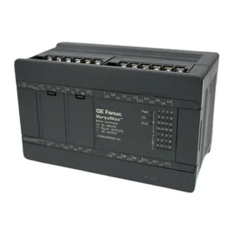
VersaMax I/O may be remotely located. Remote I/O interfaces for Genius, DeviceNet, Profibus, and Ethernet are available. 1.2 CPU Modules for VersaMax PLCs A VersaMax PLC consists of a group of VersaMax modules with a VersaMax CPU and attached power supply in the first position. VersaMax PLC CPU... - Page 19 CPU001 CPU005 CPU002 Status LEDs Serial Ports CPUE05 Ethernet Interface Introduction GFK-1503E User Manual 19 For public disclosure...
-
Page 20: Ez Program Store
1.2.3 EZ Program Store The EZ Program Store device (IC200ACC003) can be used to store and update the configuration, application program, and reference table data of a VersaMax PLC. A programmer and PLC CPU are used to initially write data to the device. -
Page 21: Available Power Supplies And Carrier
1.3.1 Available Power Supplies and Carrier The following VersaMax power supplies and carrier are available: 24VDC Power Supply IC200PWR001 24VDC Expanded 3.3V Power Supply IC200PWR002 120/240VAC Power Supply IC200PWR101 120/240VAC Expanded 3.3V Power Supply IC200PWR102 12VDC Power Supply IC200PWR201 12VDC Expanded 3.3V Power Supply IC200PWR202 Power Supply Booster Carrier IC200PWB001... -
Page 22: Available I/O Modules
Output 12/24VDC Positive Logic 0.5A per Point (2 Groups of 16) 32 Point IC200MDL750 Module Output Relay 2.0A per Point Isolated Form A 8 Point Module IC200MDL930 Output Relay 2.0A per Point Isolated Form A 16 Point Module IC200MDL940 GFK-1503E VersaMax PLC User Manual For public disclosure... - Page 23 Discrete Mixed I/O Modules Mixed 24VDC Positive Logic Input Grouped 20 Point / Output Relay 2.0A IC200MDD840 per Point Grouped 12 Point Module Mixed 24VDC Positive Logic Input 20 Point / Output 12 Point / (4) High IC200MDD841 Speed Counter, PWM, or Pulse Train Configurable Points Mixed 16 Point Grouped Input 24VDC Pos/Neg Logic / 16 Pt Grouped IC200MDD842 Output 24VDC Pos.
- Page 24 Analog Mixed Module, 0 to +10VDC Input 4 Channels, Output 0 to +10VDC IC200ALG431 2 Channels Analog Mixed Module, 12 Bit -10 to +10VDC, Input 4 Channels / Output -10 IC200ALG432 to +10VDC 2 Channels GFK-1503E VersaMax PLC User Manual For public disclosure...
-
Page 25: Carriers
1.5 Carriers Carriers provide mounting, backplane communications, and field wiring connections for all types of VersaMax modules. I/O modules can be installed on carriers or removed without disturbing field wiring. There are three basic I/O Carrier types: • Terminal-style I/O carriers. Modules mount parallel to the DIN rail. •... -
Page 26: Available Carriers And Terminal Strips
Auxiliary I/O Terminal Strips for use with Terminal-style I/O Carriers and Interposing Terminals Barrier-Style Auxiliary I/O Terminal Strip IC200TBM001 Box-Style Auxiliary I/O Terminal Strip IC200TBM002 Spring-Style Auxiliary I/O Terminal Strip IC200TBM005 Other Carriers Communications Carrier IC200CHS006 Power Supply Booster Carrier IC200PWB001 GFK-1503E VersaMax PLC User Manual For public disclosure... -
Page 27: Expansion Modules
1.6 Expansion Modules There are two basic types of VersaMax I/O expansion systems, Multi-Rack and Single-ended: Multi-Rack: A VersaMax PLC or NIU I/O Station with an Expansion Transmitter • Module (IC200ETM001) and one to seven expansion “racks”, each with an Expansion Receiver Module (IC200ERM001 or IC200ERM002). -
Page 28: Available Expansion Modules
IC200CBL615 Firmware Update Cable IC200CBL002 Terminator Plug (included with ETM) IC200ACC201 Connector Kit IC200ACC302 Refer to the VersaMax Modules, Power Supplies, and Carriers User Manual (GFK-1504) for information about VersaMax Expansion modules. GFK-1503E VersaMax PLC User Manual For public disclosure... -
Page 29: Communications Modules
1.7.2 Profibus-DP Network Slave Module The Profibus-DP Network Slave Module (IC200BEM002) is a communications module that exchanges PLC reference table data on the Profibus network. The VersaMax PLC CPU can read and write this data as though it were conventional bit- and word-type I/O data. -
Page 30: Devicenet Network Control Module
512 bytes of input data and 512 bytes of output data with other devices on the DeviceNet network. The VersaMax PLC CPU can read and write this data as though it were conventional bit- and word-type I/O data. -
Page 31: Cpu Module Datasheets: Cpu001, Cpu002, Cpu005
• IC200CPU005 CPU with 128kB configurable memory VersaMax PLC CPUs IC200CPU001, CPU002, and CPU005 provide powerful PLC functionality in a small, versatile system. They are designed to serve as the system controller for up to 64 modules with up to 2048 I/O points. Two serial ports provide RS-232 and RS-485 interfaces for SNP slave and RTU slave communications. -
Page 32: Features
Time of day clock accuracy 23ppm (0.0023%) or +/- 2sec/day @ 30C 100 ppm (0.01%) or +/- 9sec/day @ full temperature range † CPU005 requires a power supply with expanded 3.3V. GFK-1503E VersaMax PLC User Manual For public disclosure... -
Page 33: Versamax General Product Specifications
2.3 VersaMax General Product Specifications VersaMax products should be installed and used in conformance with product-specific guidelines as well as the following specifications: Environmental 1G @57-150Hz, 0.012in p–p @10-57Hz Vibration IEC68-2-6 15G, 11ms Shock IEC68-2-27 Operating Temp. 0 deg C to +60 deg C ambient Storage Temp. -
Page 34: Serial Ports
Defaults to SNP slave Defaults to SNP slave RTU master/slave, Serial I/O) Firmware Upgrade PLC in Stop/No I/O mode Smart module firmware PLC in Stop/No I/O mode PLC in Stop/No IO mode upgrade GFK-1503E VersaMax PLC User Manual For public disclosure... -
Page 35: Serial Port Baud Rates
2.4.1 Serial Port Baud Rates CPU001, CPU002 CPU005 †† RTU protocol 1200, 2400, 4800, 9600, 1200, 2400, 4800, 9600, 19.2K 19.2K, 38.4K † , 57.6K † 1200, 2400, 4800, 9600, Serial I/O protocol 1200, 2400, 4800, 9600, 19.2K 19.2K, 38.4K †... -
Page 36: Cpu Leds
OK LED is OFF, a fatal fault was detected during PLC powerup diagnostics. Contact PLC Field Service FORCE ON if an override is active on a bit reference. PORT 1 Blinking indicates activity on that port. PORT 2 GFK-1503E VersaMax PLC User Manual For public disclosure... -
Page 37: Configurable Memory
2.7 Configurable Memory CPU001 and CPU002 (release 2.0 or later) and CPU005 have configurable user memory. The configurable memory is the amount of memory required for the application program, hardware configuration, registers (%R), analog inputs (%AI), and analog outputs (%AQ). The amount of memory allocated to the application program and hardware configuration are automatically determined by the actual program and configuration entered from the programmer. - Page 38 Notes GFK-1503E VersaMax PLC User Manual For public disclosure...
-
Page 39: Cpu Module Datasheet: Cpue05
IC200CPUE05: CPU with two serial ports, embedded Ethernet interface, and 128K configurable memory CPU IC200CPUE05 shares the basic features of the other VersaMax PLC CPUs. It provides powerful PLC functionality in a small, versatile system. CPUE05 can serve as the system controller for up to 64 modules with up to 2048 I/O points. Two serial ports provide RS-232 and RS-485 interfaces for serial communications. -
Page 40: Features
Battery backup for program, data, and time of day clock • Run/Stop switch • Floating point (real) data functions • Embedded RS-232 and RS-485 communications • Embedded Ethernet interface • 70mm height when mounted on DIN rail with power supply GFK-1503E VersaMax PLC User Manual For public disclosure... -
Page 41: Module Specifications
3.2 Module Specifications 4.95” (126mm) x 5.04” (128mm) Size Program storage System flash, battery-backed RAM Super capacitor provides power to memory for 1 hour Battery backup for program, data, and Over 1 hour, backup battery protects memory contents up to 6 months. time-of-day clockl Backup battery has shelf life of 5 years when not in use. -
Page 42: Versamax General Product Specifications
Conducted RF EN 61000-4-6 Isolation UL508, UL840, Dielectric Withstand 1.5KV IEC664 Power Supply During Operation: Dips to 30% and 100%, Variation for AC Input Dips, Variations EN 61000-4-11 +/-10%, Variation for DC +/-20% GFK-1503E VersaMax PLC User Manual For public disclosure... -
Page 43: Serial Ports
3.4 Serial Ports The two serial ports are software-configurable for SNP slave or RTU master or slave operation. 4-wire and 2-wire RTU are supported. If a port is being used for RTU, it automatically switches to SNP slave mode if necessary. Port 1 can also be configured for Local Station Manager operation to provide access to diagnostic information about the Ethernet interface. -
Page 44: Cable Lengths
For RTU, an Unsupported Feature in Configuration fault is logged and the PLC transitions to Stop Faulted mode. For Serial I/O, the same fault is logged when the transition to Run mode occurs. The PLC will immediately transition to Stop Faulted mode. GFK-1503E VersaMax PLC User Manual For public disclosure... -
Page 45: Ethernet Lan Port
3.5 Ethernet LAN Port The Ethernet LAN port supports SRTP Server and Ethernet Global Data. This port connects directly to a 10BaseT (twisted pair shielded) network without an external transceiver. The 10BaseT twisted pair shielded cables must meet applicable IEEE 802 standards. -
Page 46: Cpu Leds
PLC powerup diagnostics. Contact PLC Field Service FORCE ON if an override is active on a bit reference. PORT 1 Blinking indicates activity on that port when controlled by PORT 2 the CPU. GFK-1503E VersaMax PLC User Manual For public disclosure... -
Page 47: Ethernet Restart Pushbutton
3.8 Ethernet Restart Pushbutton The Ethernet Restart pushbutton is located on the right side of the module. IP Address Writable Area Ethernet Restart Pushbutton Ethernet LEDs The Ethernet Restart pushbutton has two functions: • When pressed for less than 5 seconds, it resets the Ethernet hardware, tests the Ethernet LEDs, and restarts the Ethernet firmware. -
Page 48: Configurable Memory
Application program size (not configurable) 128 bytes minimum Hardware configuration size (not 528 bytes minimum configurable) Registers (%R) 256 bytes minimum Analog Inputs (%AI) 256 bytes minimum Analog Outputs (%AQ) 256 bytes minimum GFK-1503E VersaMax PLC User Manual For public disclosure... -
Page 49: Ethernet Interface Overview
Password security for commands that change station parameters or operation. Use of the Station Manager function requires a separate computer terminal or terminal emulator. Refer to the VersaMax PLC Ethernet Station Manager Manual (GFK-1876) for information about Station Manager operation. CPU Module Datasheet: CPUE05... - Page 50 Notes GFK-1503E VersaMax PLC User Manual For public disclosure...
-
Page 51: Installation
4 Installation This chapter describes: • Installing the CPU • Installing the power supply • Installing additional modules • Activating or replacing the backup battery • Serial port connections • Installing expansion modules • Ethernet connection for CPUE05 • CE Mark installation requirements System installation instructions, which give guidelines for carrier, power supply, and module installation, as well as information about field wiring and grounding, are located in the VersaMax Modules, Power Supplies, and Carriers Manual (GFK-1504). -
Page 52: Mounting Instructions
Using the module as a template, mark the location of the module’s panel-mount hole on the panel. Drill the hole in the panel. Install the module using an M3.5 (#6) screw in the panel-mount hole. GFK-1503E VersaMax PLC User Manual For public disclosure... - Page 53 Note 1. Tolerances on all dimensions are +/- 0.13mm +/-0.005in) noncumulative. Note 2. Apply 1.1 to 1.4Nm (10 to 12 in/lbs) of torque to the M3.5 (#6-32) steel screw threaded into material containing internal threads and having a minimum thickness of 2.4mm (0.093in).
-
Page 54: Installing An Expansion Transmitter Module
4.2 Installing an Expansion Transmitter Module If the VersaMax PLC will have more than one expansion rack or one expansion rack that uses an Isolated Expansion Receiver Module (IC200ERM001) as its interface to the expansion bus, an Expansion Transmitter Module must be installed to the left of the CPU. -
Page 55: Installing An Expansion Receiver Module
4.3 Installing an Expansion Receiver Module An Expansion Receiver Module (IC200ERM001 or 002) must be installed in the leftmost slot of each VersaMax expansion rack. Insert the label inside the small access door at the upper left corner of the module. Attach the module to the DIN rail at the left end of the expansion rack. -
Page 56: Connecting The Expansion Cable: Rs-485 Differential
Receivers are the Isolated type (IC200ERM001), the maximum overall cable length is 750 meters. If the expansion bus includes any non-isolated Expansion Receivers (IC200ERM002), the maximum overall cable length is 15 meters. VersaMax PLC or I/O Station Main Rack (0) CPU/NIU VersaMax ExpansionRack 1... -
Page 57: Connecting The Expansion Cable: Single-Ended
Expansion Receiver as shown below. The maximum cable length is one meter. Cables cannot be fabricated for this type of installation; cable IC200CBL600 must be ordered separately. VersaMax PLC or NIU I/O Station Main Rack CPU/NIU VersaMax Expansion Rack No Terminator Plug is needed in a single-ended installation; however, it will not impede system operation if installed. -
Page 58: Installing Power Supply Modules
Press the flexible panel on the lower edge of the power supply to disengage the tabs on the power supply from the holes in the carrier. Pull the power supply straight off. GFK-1503E VersaMax PLC User Manual For public disclosure... -
Page 59: Installing Additional Modules
4.5 Installing Additional Modules A CPU or Expansion Receiver Module can serve up to 8 additional I/O and option modules on the same section of DIN rail. Power must be off before adding a carrier to the rack. Before joining carriers to the CPU or ERM, remove the connector cover on the righthand side of the CPU/ERM. -
Page 60: Activating Or Replacing The Backup Battery
IC200ACC001 Panasonic BR2032 Use of another battery may present a risk of fire or explosion Battery may explode if mistreated. Caution Do not recharge, disassemble, heat above 100°C (212 °F) or incinerate. GFK-1503E VersaMax PLC User Manual For public disclosure... -
Page 61: Serial Port Connections
4.7 Serial Port Connections 4.7.1 Providing Power to an External Device from Port 2 If either port is set up for communications with a serial device that requires 100mA or less at 5VDC, the device can obtain power from Port 2. 4.7.2 Cable Lengths and Baud Rates Maximum cable lengths (the total number of feet from the CPU to the last device attached to the cable) are:... - Page 62 (2) TXD (3) TXD (3) RXD (5) GND (5) GND (7) RTS (7) CTS (8) CTS (8) RTS The shield must connect to shell of connectors on both ends of the cable. GFK-1503E VersaMax PLC User Manual For public disclosure...
- Page 63 4.7.3.3 Connector and Cable Specifications for Port 1 Vendor Part numbers below are provided for reference only. Any part that meets the same specification can be used. Computer cable, overall braid over foil shield Cable: 5 conductor † Belden 9610 30 Volt / 80°C (176°F) 24 AWG tinned copper, 7x32 stranding Type:...
- Page 64 24 AWG tinned copper, 7x32 stranding Velocity of Propagation = 78% Nominal Impedance = 100W † Type: Plug: Vendor: Pin: 15 Pin Male Crimp ITT/Cannon DAA15PK87F0 030-2487-017 Connector: 205206-1 66506-9 – ITT/Cannon ZDA15P Solder – 747908-2 GFK-1503E VersaMax PLC User Manual For public disclosure...
-
Page 65: Point-To-Point Connection With Handshaking
Kit* – ITT Cannon DA121073-50 [15-pin size backshell kit]: Metal-Plated Plastic (Plastic with Nickel over Copper) † Cable Grounding Clamp (included) Connector 40° cable exit design to maintain low-profile installation Shell: Plus – ITT Cannon 250-8501-009 [Extended Jackscrew]: Threaded with (metric) M3x0.5 for secure attachment †... - Page 66 9 and pin 10 inside the D-shell connector. Ground Potential: Multiple units not connected to the same power source must have common ground potential or ground isolation for proper operation of the system. GFK-1503E VersaMax PLC User Manual For public disclosure...
-
Page 67: Ethernet Connection For Cpue05
Connect the port to an external 10BaseT hub or switch or a hub or repeater with autosense of 10/100 using a twisted pair cable. Cables are readily available from commercial distributors. GE recommends purchasing rather than making cables. Your 10BaseT twisted pair shielded cables must meet the applicable IEEE 802 standards. -
Page 68: Ce Mark Installation Requirements
The following requirements for surge, electrostatic discharge (ESD), and fast transient burst (FTB) protection must be met for applications that require CE Mark listing: • The VersaMax PLC is considered to be open equipment and should therefore be installed in an enclosure (IP54). •... -
Page 69: Configuration
5 Configuration This chapter describes the process by which a VersaMax® CPU and the modules it serves are configured. Configuration determines certain characteristics of module operation and also establishes the program references that will used by each module in the system. •... -
Page 70: Using Autoconfiguration Or Programmer Configuration
CPU will read a previously-stored configuration from its Flash memory at powerup. If RAM is the choice, the CPU will read a configuration and application program from its RAM memory at powerup. GFK-1503E VersaMax PLC User Manual For public disclosure... -
Page 71: Configuring Racks And Slots
5.2 Configuring Racks and Slots Even though a VersaMax PLC does not have a module rack, both autoconfiguration and software configuration use the traditional convention of racks and slots to identify module locations in the system. Each logical rack consists of the CPU or an Expansion Receiver module plus up to 8 additional I/O and option modules mounted on the same DIN rail. -
Page 72: Software Configuration
5.3 Software Configuration The configuration software makes it possible to create a customized configuration for the VersaMax PLC system. For CPUE05, it is also used to configure Ethernet Global Data. When you enter Hardware Configuration for VersaMax equipment folders, the default view is the Rack (Main). - Page 73 Parameter Description Default Choices Scan Parameters Sweep Mode Normal: sweep runs until it is complete. Normal Normal, Constant Sweep Constant: sweep runs for time specified in Sweep Tmr. Sweep Times If Constant Sweep mode was selected, a 100mS 5–200mS (mSecs) Constant Sweep Time (in milliseconds) can be specified.
-
Page 74: Configurable Memory For Cpu Module Ic200Cpu001, Cpu002, Cpu005
Registers (%R) 256 bytes (128 words) minimum CPU001/002, for rel. 1.50 compatibility 4,096 bytes (2048 words) Analog Inputs (%AI) 256 bytes (128 words) minimum Analog Outputs (%AQ) 256 bytes (128 words) minimum GFK-1503E VersaMax PLC User Manual For public disclosure... -
Page 75: Configurable Memory For Cpu Module Ic200Cpue05
5.3.3 Configurable Memory for CPU Module IC200CPUE05 Configurable memory 128K bytes maximum Application program size (not configurable) 128 bytes minimum Hardware configuration size (not configurable) 528 bytes minimum Registers (%R) 256 bytes (128 words) minimum Analog Inputs (%AI) 256 bytes (128 words) minimum Analog Outputs (%AQ) 256 bytes (128 words) minimum If you reconfigure memory allocation from the default sizes, storing a hardware... -
Page 76: Configuring Serial Port Parameters
5.3.4 Configuring Serial Port Parameters Both ports on a VersaMax PLC CPU are configurable for SNP slave or RTU slave operation. 4-wire and 2-wire RTU are supported. For CPUE05 only, port 1 can also be configured (on another tab) for Local Station Manager operation. The Local Station Manager parameters may differ from the Port A parameters. -
Page 77: Rtu And Serial I/O Delays
The VersaPro software allows configuration of RTU and Serial I/O at 115.2K baud. However, these baud rates are not supported by the CPU. If a configuration using these baud rates is stored to the PLC: For RTU, an Unsupported Feature in Configuration fault is logged and the PLC transitions to Stop Faulted mode. -
Page 78: Configuration Required To Use Winloader
VersaMax CPU itself, however. 5.3.8 Storing a Configuration from a Programmer Ordinarily, a VersaMax PLC system is configured by creating a configuration file on the programmer (computer), then transferring the file from the programmer to the PLC CPU via the CPU port. -
Page 79: Autoconfiguration
5.4 Autoconfiguration When autoconfiguration is enabled and no previous autoconfiguration exists, at powerup the CPU automatically reads the configuration of the modules installed in the system and creates an overall system configuration. If a previous autoconfiguration is present at powerup, the configuration is processed as described on the the following sections. Modules that have software-configurable features use their default settings when autoconfigured. -
Page 80: Diagnostic Message Summary
2. An Expansion Transmitter Module (IC200ETM001) is configured but not present. mismatch expansion bus The expansion bus speed automatically calculated by the CPU during autoconfiguration has changed. speed change unsupported A module is present that is not supported by the CPU. feature GFK-1503E VersaMax PLC User Manual For public disclosure... -
Page 81: Ethernet Configuration
6 Ethernet Configuration This chapter describes the configuration needed for the Ethernet interface of VersaMax CPU module IC200CPUE05: • Ethernet configuration overview • Configuring the characteristics of the Ethernet interface • Configuring Ethernet Global Data • Configuring Advanced User Parameters The Ethernet interface configuration described in this chapter must be set up in addition to the basic CPU configuration described in chapter 5, Configuration. -
Page 82: Ethernet Configuration Overview
Station Manager. This changes the parameters that are stored in the Ethernet interface itself. If the PLC is power-cycled or cleared, the edited configuration will be retrieved by the CPU from the Ethernet interface. GFK-1503E VersaMax PLC User Manual For public disclosure... -
Page 83: Configuring The Ethernet Interface
6.2 Configuring the Ethernet Interface The CPU’s fundamental Ethernet operating characteristics must be correctly configured for proper operation over an Ethernet network. The default configuration cannot supply valid network address data. Description Parameters Configuration Mode This is fixed as TCP/IP. It cannot be changed. The IP Address is the unique address of the Ethernet interface as a node on the network. - Page 84 CPU instead. Refer to the section, Network Time Servers Timestamping of Ethernet Global Data Exchanges in chapter 13 for more information. (This feature is supported in IC200CPUE05-HK and previous versions only.) GFK-1503E VersaMax PLC User Manual For public disclosure...
-
Page 85: Configuring Ethernet Global Data
6.3 Configuring Ethernet Global Data VersaMax CPU IC200CPUE05 can be configured for up to 32 Ethernet Global Data exchanges (any combination of produced and consumed). (Refer to the section, Ethernet Global Data in chapter 13 for a discussion of this feature). Configuration defines both the content of an exchange, its data ranges, and its operational characteristics. -
Page 86: Configuring A Global Data Exchange For A Producer
1400 bytes. The list of data ranges to be sent in an exchange specifies: High Point Description Offset Reference Low Point example: Conveyor1 in PLC1 Conveyor1 limit switch in PLC1 GFK-1503E VersaMax PLC User Manual For public disclosure... -
Page 87: Configuring A Global Data Exchange For A Consumer
6.5 Configuring a Global Data Exchange for a Consumer To receive a Global Data Exchange, configure the following information: Description Parameters The address that uniquely identifies the CPUE05 as an Ethernet Global Data device across the Local Producer ID network. The default is the same as the IP address of the CPUE05. The default can be changed. A number that identifies that specific data exchange. -
Page 88: Selective Consumption
Failure to configure any ignored bytes in the consumed exchange will result in exchange exception log and fault table entries, error status in the exchange status data, and no data being transferred for the exchange. GFK-1503E VersaMax PLC User Manual For public disclosure... -
Page 89: Configuring Advanced User Parameters
6.6 Configuring Advanced User Parameters Advanced User Parameters are internal operating parameters used by the Ethernet interface. For most applications, the default Advanced User Parameters should not be changed. If it is necessary to modify any of these parameters, it must be done by creating an Advanced User Parameter file, using any ASCII text editor. - Page 90 NTP min. poll interval for host 3 (in log(2) of nmin_poll3 6 (0006H) = 64 sec. seconds) NTP max. poll interval for host 3 (in log(2) of nmax_poll3 10 (000aH) = 1024 sec. seconds) GFK-1503E VersaMax PLC User Manual For public disclosure...
- Page 91 Description Range Name Default NTP synchronization timeout period (in 150 – 65535 nsync_tout seconds). The max. time between network 300 (012cH) (0096H – ffffH) time updates to remain synchronized). Note: The NTP feature is supported in IC200CPUE05-HK and previous versions only. Ethernet Configuration GFK-1503E User Manual 91 For public disclosure...
- Page 92 Notes GFK-1503E VersaMax PLC User Manual For public disclosure...
-
Page 93: Cpu Operation
7 CPU Operation This chapter describes the operating modes of the VersaMax PLC CPUs, and shows the relationship between the application program execution and other tasks performed by the CPU. CPU Operating Modes The application program in a PLC executes repeatedly. In addition to executing the application program, the PLC CPU regularly obtains data from input devices, sends data to output devices, performs internal housekeeping, and performs communications tasks. -
Page 94: Parts Of The Cpu Sweep
Scan Time of Solution Execution Enabled Data Output Output Scan Programmer Programmer Service Communications System System Communications Communications Application Program Diagnostics Checksum Calculation and Verification of Physical and Programmed Configuration Start Next Sweep GFK-1503E VersaMax PLC User Manual For public disclosure... - Page 95 Parts of the CPU Sweep Housekeeping includes the tasks necessary to prepare for the start of the sweep. Before starting the actual sweep, the CPU: calculates the sweep time Schedules the start of the next sweep Determines the mode of the next sweep Start of Sweep Updates the fault reference tables Housekeeping...
- Page 96 Each sweep, the CPU verifies the physical configuration of one module against its programmed configuration. A missing, additional, or mismatched module causes a fault to be generated. GFK-1503E VersaMax PLC User Manual For public disclosure...
-
Page 97: Standard Cpu Sweep Operation
7.2 Standard CPU Sweep Operation Standard Sweep operation is the normal operating mode of the PLC CPU. In Standard Sweep operation, the CPU repeatedly executes the application program, updates I/O, and performs communications and other tasks shown in the diagram: The CPU performs its start-of-sweep housekeeping tasks. -
Page 98: Cpu Stop Modes
SVCREQ 13 can be used in the application program to stop the PLC at the end of the next sweep. All I/O will go to their configured default states, and a diagnostic message will be placed in the PLC Fault Table. GFK-1503E VersaMax PLC User Manual For public disclosure... -
Page 99: Flash Memory
7.4 Flash Memory A VersaMax PLC stores the current configuration and application in nonvolatile battery-backed RAM. The programmer software can be used to store a copy of the current configuration, application program, and reference tables (excluding overrides) to Flash memory. The programmer can also be used to read a previously-stored configuration, application program, or reference tables from Flash into RAM, or to verify that Flash and RAM contain identical data. -
Page 100: Run/Stop Mode Switch Operation
Stop to Run otherwise, the Run LED blinks for 5 seconds. Toggle switch from PLC goes to STOP–NO IO Run to Stop Toggle switch from PLC goes to STOP–IO Run to Stop GFK-1503E VersaMax PLC User Manual For public disclosure... -
Page 101: Privilege Levels And Passwords
7.7 Privilege Levels and Passwords Passwords are an optional configurable feature of the VersaMax PLC. Passwords provide different levels of access privilege to the PLC when the programmer is in Online or Monitor mode. Passwords are not used if the programmer is in Offline mode. Passwords can restrict: •... -
Page 102: Protection Level Request From Programmer
In this case, it is not necessary to reenter the password to gain access to a particular level. A Clear All does not clear user flash. GFK-1503E VersaMax PLC User Manual For public disclosure... -
Page 103: Elements Of An Application Program
8 Elements of an Application Program This chapter provides basic information about the application program for a VersaMax PLC. • Structure of an application program • Subroutines • Program languages • The Instruction Set 8.1 Structure of an Application Program The application program consists of all the logic needed to control the operations of the PLC CPU and the modules in the system. -
Page 104: Subroutines
The main program is level 1. The program can include up to eight additional nested call levels. 8.2.1 Declaring a Subroutine A subroutine must be declared through the block declaration editor of the programming software. GFK-1503E VersaMax PLC User Manual For public disclosure... -
Page 105: Calling A Subroutine
8.2.2 Calling a Subroutine A subroutine invoked in the program is using a CALL instruction. Up to 64 subroutine block declarations and 64 CALL instructions are allowed for each block in the program. %I0004 %Q0001 %I0006 CALL subroutine %I0003 %I0010 %Q0010 8.3 Program Languages Programs can be created in Ladder Diagram or Instruction List format. -
Page 106: Ladder Diagram
Some program functions, such as the Jump function and Master Control Relay, can be used to control the execution of the program itself. Together, this large group of Ladder Diagram relays, coils, and functions is called the Instruction Set of the CPU. GFK-1503E VersaMax PLC User Manual For public disclosure... -
Page 107: The Instruction Set
The VersaMax PLC CPU provides a powerful Instruction Set for building application programs. As a guide to the programming capabilities of the VersaMax PLC, all of the relays, coils, functions, and other elements of the Instruction Set are summarized on the following pages. -
Page 108: Timers And Counters
Finds the base 10 logarithm of a real value. Natural Logarithm Finds the natural logarithm base of a real number. Raises the natural logarithm base to the power specified by input. Power of e GFK-1503E VersaMax PLC User Manual For public disclosure... -
Page 109: Relational Functions
8.4.5 Relational Functions Equal Tests for equality between two numbers. Not Equal Tests for nonequality between two numbers. Tests whether one number is greater than another. Passes power Greater Than if the first number is greater than the second. Greater Than or Tests whether one number is greater than or equal to another Equal To Less Than... -
Page 110: Conversion Functions
Truncates to a 16bit signed number. The range is –32,768 to →→int (from REAL) +32,767. Truncate to Double Truncates to a 32bit signed number. The range is -2,147,483,648 Precision INT (from →→dint to +2,147,483,647. REAL) GFK-1503E VersaMax PLC User Manual For public disclosure... -
Page 111: Control Functions
8.4.10 Control Functions Causes a program execution to go to a specified subroutine block. call Call Services a specified range of inputs or outputs immediately (all inputs or outputs on a module will be serviced if any addresses on do io Do I/O that module are included in the function –... - Page 112 Notes GFK-1503E VersaMax PLC User Manual For public disclosure...
-
Page 113: Program Data
9 Program Data This chapter describes the types of data that can be used in an application program, and explains how that data is stored in the VersaMax PLC’s memory. • Data memory references • Retentiveness of data • Using names and descriptions for program references •... -
Page 114: Data Memory References
Word memory is represented below. The example below shows ten addresses. Each has 16 bits that together contain one value. The PLC cannot access individual bits in word memory. addresses 12467 12004 GFK-1503E VersaMax PLC User Manual For public disclosure... -
Page 115: Bit Memory References
9.1.2 Bit Memory References Each bit memory address (reference) is on a bit boundary. Data is stored in bit memory as represented below. The illustration shows 160 individually-addressed bits, with address 1 in the upper left and address 160 in the lower right. addresses ... -
Page 116: Retentiveness Of Data
%Q and %M references that have not been declared to be retentive. • %Q and %M references that are used with non-retentive coils: − -( )- coils − -(/)- negated coils − -(S)- SET coils − -(R)- RESET coils GFK-1503E VersaMax PLC User Manual For public disclosure... -
Page 117: System Status References
9.3 System Status References The PLC stores system status data in predefined references in %S, %SA, %SB, and %SC memory. Each system status reference has a descriptive name. For example, time tick references are named T_10MS, T_100MS, T_SEC, and T_MIN. Examples of convenience references include FST_SCN, ALW_ON, and ALW_OFF. -
Page 118: Sa, %Sb, And %Sc References
PLC power. %SA0028-30 reserved Set when an unrecoverable software fault is detected in an option SFT_SIO %SA0031 module. Cleared by cycling PLC power and when the configuration matches the hardware. GFK-1503E VersaMax PLC User Manual For public disclosure... - Page 119 %SB0001-9 reserved Set when the CPU detects corrupted RAM memory at powerup. BAD_RAM %SB0010 Cleared when RAM memory is valid at powerup. Set when a password access violation occurs. Cleared when the PLC BAD_PWD %SB0011 fault table is cleared. %SB0012 reserved Set when the CPU detects an unrecoverable error in the software.
-
Page 120: How Program Functions Handle Numerical Data
They are represented in 2's Precision complement notation. Bit 32 is the sign DINT Signed Integer bit, (0 = positive, 1 = negative). Their Two’s Complement Values range is -2,147,483,648 to +2,147,483,847. GFK-1503E VersaMax PLC User Manual For public disclosure... -
Page 121: Real Numbers
9.4.1 Real Numbers The REAL data type, which can be used for some Math functions and Numerical functions, is actually floating point data. Floating-point numbers are stored in single precision IEEE-standard format. This format requires 32 bits, which occupy two (adjacent) 16-bit PLC words. -
Page 122: Time-Tick Contacts
The contacts are referenced as T_10MS (0.01 second), T_100MS (0.1 second), T_SEC (1.0 second), and T_MIN (1 minute). The following timing diagram represents the on/off time duration of these contacts. T XXXXX These time-tick contacts represent specific locations in %S memory. GFK-1503E VersaMax PLC User Manual For public disclosure... -
Page 123: Instruction Set Reference
10 Instruction Set Reference This section is a reference to the functions in the VersaMax® PLC Instruction Set: Bit Operation Functions Math and Numerical Functions Logical AND, Logical OR Add, Subtract, Multiply, Divide Exclusive OR, Logical Invert (NOT) Modulo Division Scaling Shift Right/Shift Left Square Root... -
Page 124: Bit Operation Functions
0. The Logical AND function can also be used to clear an area of word memory by ANDing the bits with another bit string known to contain all 0s. The I1 and I2 bit strings specified may overlap. GFK-1503E VersaMax PLC User Manual For public disclosure... - Page 125 10.1.2.2 Logical OR If either or both bits examined by the Logical OR function is 1, a 1 is placed in the corresponding location in output string Q. If both bits are 0, a 0 is placed in string Q in that location.
-
Page 126: Bit Operation Functions Exclusive Or
The OK output is energized whenever enable is flow, none energized. I, Q, M, T, SA, SB, SC Output Q contains the result of the operation. (not S), G, R, AI, AQ GFK-1503E VersaMax PLC User Manual For public disclosure... -
Page 127: Bit Operation Functions Exclusive Or
10.1.4 Bit Operation Functions Exclusive OR 10.1.4.1 Example In the example, whenever %I0001 is set, the bit string represented by the nickname WORD3 is cleared (set to all zeros). %I0001 XOR_ WORD WORD3 I1 Q WORD3 WORD3 I1 (WORD3) I2 (WORD3) Q (WORD3) 10.1.5 Bit Operation Functions Logical Invert (NOT) The Logical Invert (NOT) function sets the state of each bit in the output bit string Q to... -
Page 128: Bit Operation Functions Shift Bits Right, Shift Bits Left
All 1s. To do this, use the special reference nickname ALW_ON as a permissive to input B1. • All 0s. To do this, use the special reference nickname ALW_OFF as a permissive to input B1. GFK-1503E VersaMax PLC User Manual For public disclosure... -
Page 129: Bit Operation Functions Rotate Bits Right, Rotate Bits Left
The function passes power flow to the right, unless the number of bits specified to be shifted is zero. Output Q is the shifted copy of the input string. If you want the input string to be shifted, the output parameter Q must use the same memory location as the input parameter IN. -
Page 130: Bit Operation Functions Bit Test
(1 < BIT < (16 * length) ), then Q is set OFF. A string length of 1 to 256 words can be selected. BIT_ Enable TEST_ WORD Bit to be tested Output Bit number of IN GFK-1503E VersaMax PLC User Manual For public disclosure... -
Page 131: Bit Operation Functions Bit Set And Bit Clear
10.1.8.1 Parameters of the Bit Test Function Input/ Output Description Choices When the function is enabled, the bit test is enable flow performed. IN contains the first word of the data to be I, Q, M, T, S, G, R, AI, AQ operated on. -
Page 132: 10Bit Operation Functions Masked Compare
When the function receives power flow, it begins comparing the bits in the first string with the corresponding bits in the second string. Comparison continues until a miscompare is found or until the end of the string is reached. GFK-1503E VersaMax PLC User Manual For public disclosure... - Page 133 The BIT input stores the bit number where the next comparison should start (a 0 indicates the first bit in the string). The BN output stores the bit number where the last comparison occurred (where a 1 indicates the first bit in the string). Using the same reference for BIT and BN causes the compare to start at the next bit position after a miscompare;...
-
Page 134: 11Bit Operation Functions Bit Position
A string length of 1 to 256 words can be selected. The function passes power flow to the right whenever enable is ON. BIT_ Enable POS_ WORD First word Position of non-zero bit or 0 GFK-1503E VersaMax PLC User Manual For public disclosure... -
Page 135: 12Bit Operation Functions Bit Sequencer
10.1.11.1 Parameters for the Bit Position Function Input/ Output Description Choices When the function is enabled, a bit search enable flow operation is performed. IN contains the first word of the data to be I, Q, M, T, S, G, R, AI, AQ operated on. - Page 136 Word 3 (the control word) stores the state of the boolean inputs and outputs of its associated function block, in the following format: 15 14 13 12 11 10 Reserved OK (status output) EN (enable input) GFK-1503E VersaMax PLC User Manual For public disclosure...
- Page 137 10.1.12.2 Parameters for the Bit Sequencer Function Input/ Output Description Choices Address is the location of the bit sequencer’s address current step, length, and the last enable and OK status. When the function is enabled, if it was not enabled on the previous sweep and if R is not enable flow energized, the bit sequence shift is performed.
-
Page 138: Control Functions
I, Q, AI, AQ The starting address of the I/O to be serviced. The ending address of the I/O to be serviced. I, Q, AI, AQ GFK-1503E VersaMax PLC User Manual For public disclosure... - Page 139 Input/ Output Description Choices For the input scan, ALT specifies the address to store scanned input point/word values. For the I, Q, M, T, G, R, AI, AQ, output scan, ALT specifies the address to get constant, none output point/word values from to send to the I/O modules.
-
Page 140: Control Functions Call
When the Call function receives power flow, it causes the scan to go immediately to the designated subroutine block and execute it. After the subroutine block execution is complete, control returns to the point in the logic immediately following the Call instruction. GFK-1503E VersaMax PLC User Manual For public disclosure... -
Page 141: Control Functions End Of Logic
10.2.2.1 Example %I0004 %T0001 %I0006 CALL (subroutine) %I0003 %I0010 %Q0010 %I0001 10.2.3 Control Functions End of Logic The End of Logic function provides a temporary end of logic. The program executes from the first rung to the last rung or the End of Logic function, whichever is encountered first. The End of Logic function unconditionally terminates program execution. -
Page 142: Control Functions Master Control Relay (Mcr) / End Mcr
Master Control Relay is enabled–even if %I0001 is ON–the Addition function block is executed without power flow (i.e., it does not add 1 to %R0001), and %Q0001 is turned OFF. If %I0003 and %I0004 are ON, %Q0003 is turned OFF and %Q0004 remains ON. GFK-1503E VersaMax PLC User Manual For public disclosure... -
Page 143: Control Functions Jump, Label
%I0002 %I0001 %Q0001 %R0001 %R0001 %I0003 %Q0003 %I0004 %Q0004 10.2.5 Control Functions Jump, Label The Nested Jump instruction causes a portion of the program logic to be bypassed. Program execution continues at the Label specified. When the Jump is active, all coils within its scope are left at their previous states. -
Page 144: Control Functions Comment
When the Enable input receives power flow and the Step input makes Step flow an Off to On transition, the Drum Sequencer moves one step. When Reset is active, the function ignores the Step input. GFK-1503E VersaMax PLC User Manual For public disclosure... - Page 145 Input/ Output Description Choices The Reset input can be used to select a specific step in the sequence. When Enable and Reset both receive power flow, the function copies the Preset Step value in the Control Block to the active Step Reset flow reference, also in the Control Block.
- Page 146 Step is in the correct range (between 1 and length of the Pattern array) and the Preset Step is not used, the drum will not function if the Preset Step is not in the proper range. GFK-1503E VersaMax PLC User Manual For public disclosure...
-
Page 147: Data Move Functions
10.3 Data Move Functions The Data Move functions of the Instruction Set provide basic data move capabilities. • Move Data. This function copies data as individual bits, so the new location does not have to be the same data type. •... - Page 148 For MOVE_BOOL, any discrete reference may be used; it For bit/ word does not need to be byte aligned. However, 16 bits, data: SA, SB, beginning with the reference address specified, are displayed online. For real data: R, AI, AQ GFK-1503E VersaMax PLC User Manual For public disclosure...
-
Page 149: Data Move Functions Block Move
10.3.1.2 Example 1 When enabling input %Q0014 is ON, 48 bits are moved from memory location %M0001 to memory location %M0033. (%M0001 and %M0003 are defined as WORD types if length 3.) %Q0014 MOVE WORD %M0001 %M0033 Even though the destination overlaps the source for 16 bits, the move is done correctly. Before using the Move function: INPUT (%M0001 through %M0048) %M0016... -
Page 150: Data Move Functions Block Clear
IN. When the data to be cleared is from discrete memory (%I, %Q, %M, % G, or %T), the transition information associated with the references is also cleared. The function passes power to the right whenever power is received. Enable Word to be cleared GFK-1503E VersaMax PLC User Manual For public disclosure... -
Page 151: Data Move Functions Shift Register
10.3.3.1 Parameters of the Block Clear Function Input/ Description Choices Output When the function is enabled, the array is enable flow cleared. IN contains the first word of the array to be I, Q, M, T, SA, SB, SC, cleared. The length of IN must be between 1 G, R, AI, AQ and 256 words. - Page 152 When the NXT_CYC reference is active and CLEAR is not active, the word from output status table location %Q0033 is shifted into the Shift Register at %R0001. The word shifted out of the Shift Register from %R0100 is stored in output %M0005. GFK-1503E VersaMax PLC User Manual For public disclosure...
-
Page 153: Data Move Functions Communication Request
NXT_CYC SHFR_ WORD CLEAR %M0005 %Q0033 %R0001 10.3.4.3 Example 2: In this example, the Shift Register operates on memory locations %M0001 through % M0100. (%M0001 is defined as type Boolean of length 100). When the reset reference CLEAR is active, the Shift Register function fills %M0001 through %M0100 with zeros. When NXT_CYC is active and CLEAR is not, the Shift Register function shifts the data in %M0001 to %M0100 down by one bit. - Page 154 + 2 Status Pointer Memory address + 3 Status Pointer Offset address + 4 Idle Timeout Value address + 5 Maximum Communication Time address + 6 to Data Block address + 133 GFK-1503E VersaMax PLC User Manual For public disclosure...
- Page 155 10.3.5.3 Example In the example, when enabling input %M0020 is ON, a Command Block starting at % R0016 is sent to communications task 1 in the device located at rack 1, slot 2 of the PLC. If an error occurs processing the COMMREQ, %Q0100 is set. %M0020 COMM_ %Q0100...
-
Page 156: Data Type Conversion Functions
In the example, whenever input %I0002 is set and no errors exist, the integer at input location %I0017 through %I0032 is converted to four BCD digits, and the result is stored in memory locations %Q0033 through %Q0048. Coil %Q1432 is used to check for successful conversion. GFK-1503E VersaMax PLC User Manual For public disclosure... -
Page 157: Data Type Conversion Functions Convert To Signed Integer
%I0002 %Q1432 IN Q %Q0033 %I0017 10.4.2 Data Type Conversion Functions Convert to Signed Integer The Convert to Signed Integer function outputs the integer equivalent of BCD-4 or Real data. The original data is not changed by this function. When the function receives power flow, it performs the conversion, making the result available via output Q. -
Page 158: Data Type Conversion Functions Convert To Double Precision Signed Integer
% R0001. The output %Q1001 is set whenever the function executes successfully. %I0002 %Q1001 IN Q %R0001 %I0017 GFK-1503E VersaMax PLC User Manual For public disclosure... -
Page 159: Data Type Conversion Functions Convert To Real Data
10.4.4 Data Type Conversion Functions Convert to Real Data The Convert to Real function outputs the real value equivalent of the input data. The original data is not changed by this function. When the function receives power flow, it performs the conversion, making the result available via output Q. -
Page 160: Data Type Conversion Functions Convert Real Data To Word Data
Q. The function passes power flow when power is received, unless the specified conversion would result in a value that is out of range or unless IN is not a number. Enable Value to be converted Output GFK-1503E VersaMax PLC User Manual For public disclosure... - Page 161 10.4.6.1 Parameters of the Truncate Function Input/ Output Description Choices When the function is enabled, the conversion is enable flow performed. IN contains a reference for the real value to be R, AI, AQ, constant truncated. The OK output is energized when the function is performed without error, unless the value is out of flow, none range or IN is NaN.
-
Page 162: Math And Numerical Functions
(I1 is on the left side constant of the mathematical expression, as in I1 + I2). INT data type only: I, Q, Range for constants in doubleprecision signed M, T, G integer operations is minimum/maximum DINT. GFK-1503E VersaMax PLC User Manual For public disclosure... - Page 163 Input/ Output Description Choices I2 contains a constant or reference for the All data types: R, AI, AQ, second value used in the operation. (I2 is on the constant right side of the mathematical expression, as in INT data type only: I, Q, I1 + I2).
-
Page 164: Math And Numerical Functions Modulo Division
OK is always ON when the function receives power flow, unless there is an attempt to divide by zero. In that case, it is set OFF. MOD_ Enable Input 1 Output I1 Q Input 2 GFK-1503E VersaMax PLC User Manual For public disclosure... -
Page 165: Math And Numerical Functions Scaling
10.5.2.1 Parameters of the Modulo Division Function Input/ Output Description Choices When the function is enabled, the operation is enable flow performed. All data types: R, AI, AQ, I1 contains a constant or reference for the value constant to be divided by I2. Range for constants in INT data type only: I, Q, M, double precision signed integer operations is T, G... -
Page 166: Math And Numerical Functions Square Root
The Square Root function operates on these types of data: Signed integer Double precision signed integer DINT Floating Point REAL OK is set ON if the function is performed without overflow, unless one of these invalid REAL operations occurs: GFK-1503E VersaMax PLC User Manual For public disclosure... -
Page 167: Math And Numerical Functions Trigonometric Functions
• IN < 0 • IN is NaN (Not a Number) Otherwise, OK is set OFF. Enable Input Output 10.5.4.1 Parameters of the Square Root Function Input/ Output Description Choices When the function is enabled, the operation is enable flow performed. - Page 168 IN is NaN. R, AI, AQ Output Q contains the trigonometric value of IN. 10.5.5.4 Example In the example, the Cosine of the value in %R0001 is placed in %R0033. GFK-1503E VersaMax PLC User Manual For public disclosure...
-
Page 169: Math And Numerical Functions Logarithmic / Exponential Functions
COS_ REAL %R0001 IN Q %R0033 +3.141500 -1.000000 10.5.6 Math and Numerical Functions Logarithmic / Exponential Functions When a Logarithmic or Exponential function receives power flow, it performs the appropriate logarithmic/exponential operation on the Real value in input IN and places the result in output Q. -
Page 170: Math And Numerical Functions Radian Conversion Functions
IN is NaN. R, AI, AQ Output Q contains the converted value of IN. 10.5.7.2 Example In the example, +1500 is converted to DEG and is placed in %R0001. RAD_ CONST %R0001 +1500.000 85943.67 GFK-1503E VersaMax PLC User Manual For public disclosure... -
Page 171: Relational Functions
10.6 Relational Functions The Relational functions can be used to compare two numbers and to determine whether a number lies within a specified range. • Equal Test two numbers for equality • Not Equal Test two numbers for non-equality • Greater Than Test whether one number is greater than another •... -
Page 172: Relational Functions Range
L1 and L2, inclusive, output parameter Q is set ON (1). Otherwise, Q is set OFF (0). RANGE Enable Limit 1 Output L1 Q Limit 2 Value to be compared GFK-1503E VersaMax PLC User Manual For public disclosure... - Page 173 10.6.2.2 Parameters for the Range Function Input/ Output Description Choices enable flow When the function is enabled, the operation is performed. R, AI, AQ, constant L1 contains the start point of the range. INT and WORD only: I, Constants must be integer values for double Q, M, T, G precision signed integer operations.
-
Page 174: Relay Functions
The example shows a rung with 10 elements having nicknames from E1 to E10. Coil E10 is ON when reference E1, E2, E5, E6, and E9 are ON and references E3, E4, E7, and E8 are OFF. GFK-1503E VersaMax PLC User Manual For public disclosure... -
Page 175: Relay Functions Coils
10.7.1.4 Continuation Coils and Contacts Continuation coils and continuation contacts are used to continue relay ladder rung logic beyond the last column. The state of the last executed continuation coil is the flow state used on the next executed continuation contact. If the flow of logic does not execute a continuation coil before it executes a continuation contact, the state of the contact is no flow. - Page 176 The negated retentive coil sets a discrete reference ON when it does not receive power flow. The state of the negated retentive coil is retained across power failure. Therefore, it cannot be used with references from strictly non-retentive memory (%T). GFK-1503E VersaMax PLC User Manual For public disclosure...
- Page 177 10.7.2.6 Positive Transition Coil If the reference associated with a positive transition coil was OFF , when the coil receives power flow it is set to ON until the next time the coil is executed. (If the rung containing the coil is skipped on subsequent sweeps, it will remain ON.) This coil can be used as a one-shot.
- Page 178 This coil sets a discrete reference OFF if it receives power flow. The reference remains OFF until set by a retentive SET coil. The state of this coil is retained across power failure or when the PLC transitions from Stop to Run mode. GFK-1503E VersaMax PLC User Manual For public disclosure...
-
Page 179: Table Functions
10.8 Table Functions The Table functions are used to: • Copy array data: ARRAY MOVE • Search for values in an array The maximum length allowed for these functions is 32,767 for any type. Data Types for the Table Functions Table functions operate on these types of data: Signed integer Double precision signed integer... - Page 180 Using bit memory for SR and DS, %M0011 - %M0017 of the array %M0009 - %M0024 is read and then written to %Q0026 - %Q0032 of the array %Q0022 - %Q0037. (%M009 and %Q0022 are declared as type BOOL of length 16). GFK-1503E VersaMax PLC User Manual For public disclosure...
-
Page 181: Table Functions Search For Array Values
%I0001 ARRAY MOVE_ BOOL %Q0022 %M0009 CONST 00003 CONST 00005 CONST 00007 10.8.1.4 Example 3: Using word memory, for SR and DS, the third least significant bit of %R0001 through the second least significant bit of %R0002 of the array containing all 16 bits of %R0001 and four bits of %R0002 is read and then written into the fifth least significant bit of %R0100 through the fourth least significant bit of %R0101 of the array containing all 16 bits of % R0100 and four bits of %R0101. - Page 182 IN. If %R0001 = 7, %R0002 = 9, %R0003 = 6, %R0004 = 7, %R0005 = 7, and %R0100 = 7, then the search will begin at %R0004 and conclude at %R0004 when FD is set ON and a 4 is written to %R0101. GFK-1503E VersaMax PLC User Manual For public disclosure...
- Page 183 %I0001 SRCH_ EQ__ %Q0001 %R0001 CONST %R0101 00003 %R0100 10.8.2.3 Example 2: Array AR is defined as memory addresses %AI001 - %AI016. The values of the array elements are 100, 20, 0, 5, 90, 200, 0, 79, 102, 80, 24, 34, 987, 8, 0, and 500. Initially, % AQ001 is 5.
-
Page 184: Timer And Counter Functions
Down Counter Time-tick Contacts In addition to the Timer functions of the Instruction Set, the VersaMax PLC has four time-tick contacts. These contacts can be used to provide regular pulses of power flow to other program functions. The four time-tick contacts have time durations of 0.01 second, 0.1 second, 1.0 second, and 1 minute. -
Page 185: Timer And Counter Functions On Delay Stopwatch Timer
The control word stores the state of the boolean inputs and outputs of its associated function block in the following format: 15 14 13 12 11 10 Reserved Reset input Enable input, previous execution Q (counter/timer status output) EN (enable input) Bits 0 through 11 are used for timer accuracy;... - Page 186 Current value becomes equal to preset value PV; Q goes high. Timer continues to accumulate time until ENABLE goes low, RESET goes high or current value becomes equal to the maximum time ENABLE goes low; timer stops accumulating time. GFK-1503E VersaMax PLC User Manual For public disclosure...
-
Page 187: Timer And Counter Functions On Delay Timer
When power flow to the timer stops, the current value stops incrementing and is retained. Output Q, if energized, will remain energized. When the function receives power flow again, the current value again increments, beginning at the retained value. When reset R receives power flow, the current value is set back to zero and output Q is de-energized unless PV equals zero. - Page 188 In the example, a delay timer (with address) TMRID is used to control the length of time that coil is on. This coil has been assigned the Nickname DWELL . When the normally open (momentary) contact with the Nickname DO_DWL is on, coil DWELL is energized. GFK-1503E VersaMax PLC User Manual For public disclosure...
-
Page 189: Timer And Counter Functions Off-Delay Timer
The contact of coil DWELL keeps coil DWELL energized (when contact DO_DWL is released), and also starts the timer TMRID. When TMRID reaches its preset value of one-half second, coil REL energizes, interrupting the latched-on condition of coil DWELL. The contact DWELL interrupts power flow to TMRID, resetting its current value and de-energizing coil REL. - Page 190 • Control word = word 3. Do not use this address with other instructions. Careful: Overlapping references cause erratic operation of the timer. When enable receives power flow, the timer’s enable flow current value is incremented. GFK-1503E VersaMax PLC User Manual For public disclosure...
-
Page 191: Timer And Counter Functions Up Counter
Input/ Output Description Choices PV is the value to copy into the timer’s preset value when the timer is enabled or reset. For a register (%R) OV reference, the PV parameter is I Q, M, T, G, R, AI, AQ, specified as the second word of the address constant, none parameter. -
Page 192: Timer And Counter Functions Down Counter
The output is ON whenever the Current Value is less than or equal to zero. The Current Value of the Down Counter is retentive on power failure; no automatic initialization occurs at power-up. Enable Reset Preset Value Address GFK-1503E VersaMax PLC User Manual For public disclosure... - Page 193 10.9.5.1 Parameters of the Down Counter Function Input/ Output Description Choices The function uses three consecutive words (registers) of %R memory to store the following: • Current value (CV) = word 1. • Preset value (PV) = word 2. • Control word = word 3. address Do not use this address with another down counter, up counter, or any other instruction or...
- Page 194 %I00003 %I00002 %I00009 CONST +00005 %R0104 %I00002 MOVE_ %I00003 %R0100 %R0104 Refer to the sections on Math functions for an example of using the Addition and Subtraction functions to provide storage tracking. GFK-1503E VersaMax PLC User Manual For public disclosure...
-
Page 195: The Service Request Function
11 The Service Request Function This chapter explains the Service Request (SVCREQ) function, which requests a special PLC service. It describes SVCREQ parameters for the VersaMax CPU. • SVCREQ Function Numbers • Format of the SVCREQ Function • SVCREQ 1: Change/Read Constant Sweep Timer •... -
Page 196: Svcreq Function Numbers
Read Last-Logged Fault Table Entry Read Elapsed Time Clock reserved Read I/O Override Status 19-22 reserved Read Master Checksum Interrogate I/O 26/30 27, 28 reserved Read Elapsed Power Down Time 31-255 reserved GFK-1503E VersaMax PLC User Manual For public disclosure... -
Page 197: Format Of The Svcreq Function
11.2 Format of the SVCREQ Function The SVCREQ function has three inputs and one output. enable Function number Beginning reference PARM When the SVCREQ receives power flow, the PLC is requested to perform the function number FNC indicated. Parameters for the function are located beginning at the reference given for PARM. -
Page 198: Svcreq 1: Change/Read Constant Sweep Timer
A number other than 0, 1, 2, or 3 is entered as the requested operation. The sweep time value is greater than 500ms (0.5 seconds). Constant sweep time is enabled with no timer value programmed or with an old value of 0 for the timer. GFK-1503E VersaMax PLC User Manual For public disclosure... - Page 199 After the function executes, the function returns the timer state and value in the same parameter block references: 0 = disabled address 1 = enabled address + 1 current timer value 11.3.1.5 Example of SVCREQ 1 In this example, if contact OV_SWP is set, the Constant SweepTimer is read, the timer is increased by two milliseconds, and the new timer value is sent back to the PLC.
-
Page 200: Svcreq 2: Read Window Times
11.4.1.1 Example of SVCREQ 2 In the following example, when enabling output %Q00102 is set, the CPU places the current time values of the windows in the parameter block starting at location %R0010. SVC_ GFK-1503E VersaMax PLC User Manual For public disclosure... -
Page 201: Svcreq 3: Change Programmer Communications Window Mode
11.5 SVCREQ 3: Change Programmer Communications Window Mode Use SVCREQ 3 to change the programmer communications window mode (Limited or Run-to-Completion). The change occurs during the next CPU sweep after the function is called. The time of the window cannot be changed; it is always 6ms. SVCREQ 3 passes power flow to the right unless a mode other than 0 (Limited) or 2 (Run-to-Completion) is selected. -
Page 202: Svcreq 4: Change System Communications Window Mode
11.6.1.1 Example of SVCREQ 4 In the following example, when enabling input %I0003 is ON the system communications window is changed to Run-to-Completion mode. The parameter block is at location % R0025. SVC_ GFK-1503E VersaMax PLC User Manual For public disclosure... -
Page 203: Change/Read Number Of Words To Checksum
11.7 Change/Read Number of Words to Checksum Use SVCREQ 6 to read or change the number of words in the program to be checksummed. The function is successful unless some number other than 0 or 1 is entered as the requested operation. 11.7.1 Parameter Block Formats for SVCREQ 6 The parameter block has a length of 2 words. - Page 204 %R00152-153. The second SVCREQ then changes to the new word count specified in %R0153. FST_SCN XOR_ MOVE %R0150 CONST IN Q %R0152 %R0150 00001 %R0150 %I0137 SVC_ SVC_ ADD_ CONST %R0151 %R0153 CONST 00006 00006 CONST %R0152 %R0150 PARM PARM 00032 GFK-1503E VersaMax PLC User Manual For public disclosure...
-
Page 205: Svcreq 7: Read Or Change The Time-Of-Day Clock
11.8 SVCREQ 7: Read or Change the Time-of-Day Clock Use SVCREQ 7 to read or change the time of day clock in the PLC. The data can be either BCD or ASCII. Either 2-digit-year or 4-digit-year format is available. The function is successful unless some number other than 0 (read) or 1 (change) is entered for the requested operation, or an invalid data format is specified, or data is provided in an unexpected format. -
Page 206: Svcreq 7 Parameter Block Content: Bcd Format
+ 2 day of 03 (day) 07 (July) month address + 3 month 45 (minutes) 14 (hours) minutes hours address + 4 day of week 06 (Friday) 30 (seconds) seconds address + 5 GFK-1503E VersaMax PLC User Manual For public disclosure... -
Page 207: Svcreq 7 Parameter Block Content: Packed Ascii Format
11.8.3 SVCREQ 7 Parameter Block Content: Packed ASCII Format In Packed ASCII format, each digit of the time and date items is an ASCII formatted byte. Spaces and colons are embedded into the data to format it for printing or display. ASCII format requires 12 words in the parameter block (13 words for 4-digit year). - Page 208 3A ( : ) address + 10 (tens) (space) seconds (ones) 20 (space) 30 (0) address + 11 day of week day of week 32 (2: Mon.) 30 (leading 0) address + 12 (ones) (tens) GFK-1503E VersaMax PLC User Manual For public disclosure...
- Page 209 11.8.3.3 Example of SVCREQ 7 In the example, when called for by previous logic, a parameter block for the time-of-day clock is built. It requests the current date and time, then sets the clock to 12 noon using BCD format. The parameter block is located at location %R0300. Array NOON has been set up elsewhere in the program to contain the values 12, 0, and 0.
-
Page 210: Svcreq 8: Reset Watchdog Timer
11.9.2 Example of SVCREQ 8 In this example, power flow through enabling output %Q0027 or input %I1476 or internal coil %M00010 causes the watchdog timer to be reset. %Q0127 SVC_ %I1476 %M0010 GFK-1503E VersaMax PLC User Manual For public disclosure... -
Page 211: Svcreq 9: Read Sweep Time From Beginning Of Sweep
11.10 SVCREQ 9: Read Sweep Time from Beginning of Sweep Use SVCREQ 9 to read the time in milliseconds since the start of the sweep. The data format is unsigned 16-bit integer. 11.10.1 Output Parameter Block Format for SVCREQ 9 The parameter block is an output parameter block only;... -
Page 212: Svcreq 10: Read Folder Name
10, which is the function code for the Read Folder Name function. The Program Block READ_ID is then called to retrieve the folder name. The parameter block is located at address %R0100. %I0301 READ_ID MOVE UINT SVC_ GFK-1503E VersaMax PLC User Manual For public disclosure... -
Page 213: Svcreq 11: Read Plc Id
11.12 SVCREQ 11: Read PLC ID Use SVCREQ 11 to read the name of the PLC executing the program. 11.12.1 Output Parameter Block Format for SVCREQ The output parameter block has a length of four words. It returns eight ASCII characters; the last is a null character (00h). -
Page 214: Svcreq 13: Shut Down (Stop) Plc
PLC function executes successfully. This JUMP and LABEL are needed because the transition to Stop mode does not occur until the end of the sweep in which the function executes. LOS_MD %T0001 %T0001 >> END_PRG SVC_ CONST 00013 PARM END_PRG GFK-1503E VersaMax PLC User Manual For public disclosure... -
Page 215: Svcreq 14: Clear Fault
11.14 SVCREQ 14: Clear Fault Use SVCREQ 14 to clear either the PLC fault table or the I/O fault table. The SVCREQ output is set ON unless some number other than 0 or 1 is entered as the requested operation. 11.14.1 Input Parameter Block for SVCREQ 14 For this function, the parameter block has a length of 1 word. -
Page 216: Svcreq 15: Read Last-Logged Fault Table Entry
+ 20 hour 2-Digit Year year year month address + 21 month Format spare spare 4-Digit Year month address + 21 month year year Format address + 22 GFK-1503E VersaMax PLC User Manual For public disclosure... -
Page 217: 2Long/Short Value
11.15.2 Long/Short Value The first byte of word address +1 contains a number that indicates the length of the fault-specific data in the fault entry. These possible values are: 00 = 8 bytes (short) PLC fault table 01 = 24 bytes (long) 02 = 5 bytes (short) I/O fault table 03 = 21 bytes (long) -
Page 218: Svcreq 16: Read Elapsed Time Clock
The difference between the two readings is placed in memory location %R0250. %M0234 %M0223 SVC_ CONST 00016 PARM %R0127 %M0234 %M0233 %M0234 SVC_ SUB_ D INT %R0250 CONST %R0131 00016 %R0127 %R0131 PARM GFK-1503E VersaMax PLC User Manual For public disclosure... -
Page 219: Svcreq 18: Read I/O Override Status
11.17 SVCREQ 18: Read I/O Override Status Use SVCREQ 18 to check for any overrides in the CPU's %I and %Q memories. 11.17.1 Output Parameter Block for SVCREQ 18 This function has an output parameter block only. Its length is 1 word. address 0 = No overrides are set. -
Page 220: Svcreq 23: Read Master Checksum
In the example, when input %I0251 is ON, the master checksum information is placed into the parameter block at %R0050 and the output coil (%Q0001) is turned on. %I0251 %Q0001 SVC_ CONST 00023 %R0050 PARM GFK-1503E VersaMax PLC User Manual For public disclosure... -
Page 221: Svcreq 24: Reset Ethernet Daughter Board
11.19 SVCREQ 24: Reset Ethernet Daughter Board Service request #24 is added for user to reset Ethernet daughterboard from ladder. The FNC number “24” is the instruction number to reset Ethernet daughterboard on IC200CPUE05. The first WORD in the parameter block for the SVC_REQ #24 should be “0”... -
Page 222: Svcreq 26/30: Interrogate I/O
In the example, when input %I0251 is ON, the SVCREQ checks the installed modules and compares them to the software configuration. Output %Q0001 is turned on after the SVCREQ is complete. %I0251 %Q0001 SVC_ CONST 00026 %R0050 PARM GFK-1503E VersaMax PLC User Manual For public disclosure... -
Page 223: Svcreq 29: Read Elapsed Power Down Time
11.21 SVCREQ 29: Read Elapsed Power Down Time Use SVCREQ 29 to read the amount of time elapsed between the last power-down and the most recent powerup. If the watchdog timer expired before power-down, the PLC is not able to calculate the power down elapsed time, so the time is set to 0. The SVCREQ output is always ON. - Page 224 Notes GFK-1503E VersaMax PLC User Manual For public disclosure...
-
Page 225: Serial I/O / Snp / Rtu Protocols
12 Serial I/O / SNP / RTU Protocols This chapter describes the VersaMax® CPU’s Serial I/O feature, which can be used to control the read/write activities of one of the CPU ports directly from the application program. This chapter also contains instructions for using COMMREQs to configure the CPU serial ports for SNP, RTU, or Serial I/O protocol. -
Page 226: Format Of The Communication Request Function
• The specified task is not valid for the device (TASK). • The data length is 0. • The device’s status pointer address (in the command block) does not exist. GFK-1503E VersaMax PLC User Manual For public disclosure... -
Page 227: Command Block For The Commreq Function
12.1.2 Command Block for the COMMREQ Function The Command Block starts at the reference specified in COMMREQ parameter IN. The length of the Command Block depends on the amount of data sent to the device. The Command Block contains the data to be communicated to the other device, plus information related to the execution of the COMMREQ. -
Page 228: Configuring Serial Ports Using The Commreq Function
This applies to a new protocol installed by Storing a new hardware configuration or by a port configuration COMMREQ. If the port is configured for Serial I/O, this waiting period must also follow any Stop to Run mode transition of the CPU. GFK-1503E VersaMax PLC User Manual For public disclosure... -
Page 229: Invalid Port Configuration Combinations
12.2.3 Invalid Port Configuration Combinations The configurations of both ports must be compatible. One port must be available for PLC programmer connection. The CPU rejects the following combinations: Port 1 Port 2 Disabled Disabled Serial I/O Disabled (CPU Run/Stop switch disabled) Serial I/O Disabled (CPU Run/Stop switch disabled) -
Page 230: Example Commreq Command Block For Configuring Snp Protocol
† Device identifier bytes 1 and 2 Address + 18 user-provided † Device identifier bytes 3 and 4 Address + 19 user-provided † Device identifier bytes 5 and 6 Address + 20 GFK-1503E VersaMax PLC User Manual For public disclosure... -
Page 231: Example Commreq Data Block For Configuring Rtu Protocol
Meaning Values user-provided † Device identifier bytes 7 and 8 Address + 21 † The device identifier for SNP Slave ports is packed into words with the least significant character in the least significant byte of the word. For example, if the first two characters are “A”... -
Page 232: Example Commreq Data Block For Configuring Serial I/O Protocol
Note If Serial I/O is configured for 115.2K baud. a major error code 12 (0cH) and a minor error code 2 (02H) is returned in the COMMREQ status word. This will occur for any unsupported baud rate. GFK-1503E VersaMax PLC User Manual For public disclosure... -
Page 233: Calling Serial I/O Commreqs From The Plc Sweep
12.3 Calling Serial I/O COMMREQs from the PLC Sweep Implementing a serial protocol using Serial I/O COMMREQs may be restricted by the PLC sweep time. For example, if the protocol requires that a reply to a certain message from the remote device be initiated within 5mS of receiving the message, this method may not be successful if the PLC sweep time is 5mS or longer, since timely response is not guaranteed. - Page 234 Check the modem connections and the telephone line. Modem responded with ERROR. Modem is unable to 9 (09h) complete the requested command. Check the modem command string and modem. GFK-1503E VersaMax PLC User Manual For public disclosure...
- Page 235 Major Error Description Code Modem responded with RING, indicating that the modem is being called by another modem. Modem is unable to 10 (0Ah) complete the requested command. Retry the modem command later. Unknown response received from the modem. Modem 11 (0Bh) unable to complete the request.
-
Page 236: Serial I/O Commreq Commands
Initialize Port (4300) • Set Up Input Buffer (4301) • Flush Input Buffer (4302) • Read Port Status (4303) • Write Port Control (4304) • Cancel Operation (4399) • Serial Port Setup (FFF0) GFK-1503E VersaMax PLC User Manual For public disclosure... -
Page 237: Commreqs That Can Be Pending While Others Execute
12.4.3 COMMREQs that Can be Pending While Others Execute The table below shows whether Write Bytes, Read Bytes and Read String COMMREQs can be pending when other COMMREQs are executed. NEW COMMREQ Set Up Flush Read Write Serial Write Initialize Read Read Cancel... -
Page 238: Set Up Input Buffer Function (4301)
12.4.6 Flush Input Buffer Function (4302) This operation empties the input buffer of any characters received through the serial port but not yet retrieved using a read command. All such characters are lost. GFK-1503E VersaMax PLC User Manual For public disclosure... -
Page 239: Read Port Status Function (4303)
12.4.6.1 Example Command Block for the Flush Input Buffer Function VALUE VALUE (hexadeci- MEANING (decimal) mal) Data block length address 0001 0001 address +1 0000 0000 NOWAIT mode Status word memory type (%R) address +2 0008 0008 Status word address minus 1 (% address +3 0000 0000... - Page 240 The port status consists of a status word and the number of characters in the input buffer that have not been retrieved by the application (characters which have been received and are available). Port status word (see below) word 1 Characters available in the input buffer word 2 GFK-1503E VersaMax PLC User Manual For public disclosure...
- Page 241 The Port Status Word can be: Meaning Name Definition Read In progress Read Bytes or Read String invoked Previous Read bytes or String has Cleared timed out, been canceled, or finished Read Bytes or Read String has Read Success successfully completed New Read Bytes or Read String Cleared invoked...
-
Page 242: Write Port Control Function (4304)
4-wire Duplex Mode) when data is being transmitted. For point-to-point Duplex Mode, the transmit driver is always enabled. Therefore, in point-to-point Duplex Mode, RTS on the serial line will always reflect what is chosen with the Write Port Control COMMREQ. GFK-1503E VersaMax PLC User Manual For public disclosure... -
Page 243: Cancel Commreq Function (4399)
12.4.9 Cancel Commreq Function (4399) This function cancels the current operations in progress. It can be used to cancel both read operations and write operations. If a read operation is in progress and there are unprocessed characters in the input buffer, those characters are left in the input buffer and available for future reads. - Page 244 A (41h), T (54h) 5441h D (44h), T (54h) 5444h Phone 2 (32h), 3 (33h) 3332h number: 4 (34h), 5 (35h) 3534h 6 (36h), 7 (37h) 3736h 8 (38h) <CR> (0Dh) 0D38h GFK-1503E VersaMax PLC User Manual For public disclosure...
-
Page 245: 11Write Bytes Function (4401)
12.4.11 Write Bytes Function (4401) This operation can be used to transmit one or more characters to the remote device through the specified serial port. The character(s) to be transmitted must be in a word reference memory . They should not be changed until the operation is complete. Up to 250 characters can be transmitted with a single invocation of this operation. -
Page 246: 12Read Bytes Function (4402)
Read time-out (30 seconds) address +7 0030 001E Number of bytes to read address +8 0005 0005 Input data memory type (%R). address +9 0008 0008 Input data memory address (%R0100) address +10 0100 0064 GFK-1503E VersaMax PLC User Manual For public disclosure... -
Page 247: 13Read String Function (4403)
12.4.12.2 Return Data Format for the Read Bytes Function The return data consists of the number of characters actually read, the number of characters still available in the input buffer after the read is complete (if any), and the actual input characters. Number of characters actually read Address Number of characters still available in the input... - Page 248 As data is received from the serial port it is placed in the internal input buffer. If the buffer becomes full, then any additional data received from the serial port is discarded and the Overflow Error bit in the Port Status word (See Read Port Status Function) is set. GFK-1503E VersaMax PLC User Manual For public disclosure...
-
Page 249: Ethernet Communications
13 Ethernet Communications This chapter describes the Ethernet communications features of VersaMax® CPU model IC200CPUE05. • Overview of the Ethernet interface • IP Addressing • Routers • Ethernet Global Data • Checking the status of an Ethernet Global Data exchange •... -
Page 250: Overview Of The Ethernet Interface
Maintain compatibility with other devices. CPUE05 is compatible with the GE • Series 90-30 Ethernet Interface, Series 90-30 CPU364 Embedded Ethernet Interface, and Series 90-70 Ethernet Interface (Type 2). It is also compatible with GE programming packages supporting TCP/IP Ethernet communications. 13.1.1 Ethernet Global Data CPUE05 also supports up to 32 simultaneous Ethernet Global Data exchanges. -
Page 251: Srtp Server
13.1.2 SRTP Server CPUE05 supports up to eight simultaneous SRTP Server connections for use by other devices on the Ethernet network, such as the PLC programmer, CIMPLICITY HMI, SRTP channels for Series 90 PLCs, and Host Communications Toolkit applications. No PLC programming is required for server operation. -
Page 252: Ip Addressing
RFC 1918 reserves IP addresses in the following ranges for private networks. 10.0.0.0 – 10.255.255.255 (Class A) 172.16.0.0 – 172.31.255.255 (Class B) 192.168.0.0 – 192.168.255.255 (Class C) x.y.z.1 is reserved for gateways. x.y.z.255 is reserved for subnet broadcast GFK-1503E VersaMax PLC User Manual For public disclosure... -
Page 253: Routers
13.3 Routers Routers connect individual physical networks into a system of networks. When a node on one network needs to communicate with a node on another network, a Router transfers the data between the two networks. Example: Networks Connected by a Router The following figure shows Network 1 and Network 2 connected by Router R. -
Page 254: Ethernet Global Data
The range is 0 for no timeout detection, or 10 to 3,600,000 milliseconds. The consumer’s timeout period should be greater than the producer’s repetition period. GE recommends that the consumer timeout be set to no lower than twice the production period,... -
Page 255: Ethernet Global Data Groups
13.4.3 Ethernet Global Data Groups If more than one device on the network should consume a Global Data exchange, those devices can be set up as a group. The network can include up to 32 numbered groups. Groups allow each sample from the producer to be seen simultaneously by all consumers in the group. - Page 256 CPU. Because the clocks in the other devices on the network are not synchronized with the CPUE05, their timestamps cannot be compared accurately. Ethernet CPUE05 interface time CPU Time clock time timestamp clock GFK-1503E VersaMax PLC User Manual For public disclosure...
-
Page 257: Configuring Ntp For The Cpue05 Ethernet Interface
NTP Server Time Clock: If time servers are configured and present on the • network (see chapter 6 for configuration details), the Ethernet interface’s built-in clock is periodically synchronized to the clock from one to three NTP servers on the network. -
Page 258: The Content Of An Ethernet Global Data Exchange
A consumer does not have to consume all of the data from a produced exchange. A consumed exchange may be configured to ignore specified data ranges. (See “Selective Consumption” in chapter 6.) GFK-1503E VersaMax PLC User Manual For public disclosure... -
Page 259: Effect Of Plc Modes And Actions On Ethernet Global Data
13.4.8 Effect of PLC Modes and Actions on Ethernet Global Data The usual PLC mode for Ethernet Global Data operation is Run with I/O enabled. In that mode, Ethernet Global Data remains configured and exchanges are both produced and consumed. If the PLC mode is set to Stop with I/O disabled, the Producer ID remains configured, but production and consumption stops. - Page 260 More than one sample can be produced per producer period expiration and stale samples are produced to the network. Producer Period = 2/3 Time of CPU Sweep Producer PLC Output Scan Ethernet Global Data Production Timer Expires Sample on Network Stale Data is Produced GFK-1503E VersaMax PLC User Manual For public disclosure...
-
Page 261: Diagnostic Tools
Station Manager. 13.5.1 What to do if you Cannot Solve the Problem If you still cannot solve your problem, call GE Automation – NA, 1- 800-433–2682. Please have the following information available when you call. - Page 262 OFF if the module is not connected to the network. If the STAT LED is amber, check the PLC Fault Table. With the Station Manager feature, you can also use the LOG command as explained in the VersaMax PLC Ethernet Station Manager Manual ( GFK-1876).
- Page 263 Ethernet LEDs Indications Actions Waiting for Ethernet configuration ▪ Use the PLC programmer to update the data from CPU. configuration, then store the configuration to PORT 1: PLC CPU is controlling Port the PLC. ▪ Power cycle the PLC. ▪ Clear faults and press the Restart pushbutton for less than 5 seconds to restart the Ethernet interface.
-
Page 264: Using The Plc Fault Table
Event This information can be used to refer directly to detailed fault descriptions included in the Log event table under the LOG command in the VersaMax PLC Station Manager Manual (GFK-1876). Please note some internal system errors display error messages as ASCII text in the fault extra data. -
Page 265: Checking The Status Of The Ethernet Interface
LAN system-software fault; restarted LAN IF LAN system-software fault; resuming Module software corrupted; requesting reload Catastrophic internal system error. Contact GE Automation – NA. COMMREQ received when Ethernet interface cannot process Module state doesn’t permit Comm_Req; discarded COMMREQ. Make sure Ethernet interface is configured and online. -
Page 266: Checking The Status Of An Ethernet Global Data Exchange
Ethernet Global Data configuration is stored to the PLC • the PLC powers up and it has an Ethernet Global Data configuration • the Ethernet interface configured for Ethernet Global Data is restarted GFK-1503E VersaMax PLC User Manual For public disclosure... - Page 267 If the application program uses the Exchange Status word to check exchange status, it must clear this word to 0 once a non-zero value is written to it. That allows the application program to detect a new exchange status in subsequent sweeps. The Exchange Status word uses the error codes below to report exchange status.
-
Page 268: Using The Ethernet Station Manager Function
Unlike some Series 90 Ethernet products, CPUE05 cannot send or receive remote Station Manager messages that have been sent to a specified MAC address. For a detailed description of Station Manager functions, refer to the VersaMax PLC Ethernet Station Manager User Manual (GFK-1876). -
Page 269: Troubleshooting Common Ethernet Difficulties
13.6 Troubleshooting Common Ethernet Difficulties Some common Ethernet errors are described below. Ethernet errors are generally indicated in the PLC Fault Table and the Ethernet exception log. As previously explained in Using the PLC Fault Table, PLC Faults generated by the Ethernet interface contain Ethernet exception events within the extra fault data. -
Page 270: Unexpected Ethernet Restart Or Runtime Errors
CPUE05 is connected to a repeater-type network hub, the primary remedy is to replace the repeater-type hub with a switching-type network hub. A secondary remedy is to reduce the number, size, or frequency of the EGD exchanges and/or transfers over SRTP connections. GFK-1503E VersaMax PLC User Manual For public disclosure... -
Page 271: Egd Configuration Mismatch Errors
13.6.3 EGD Configuration Mismatch Errors When using Ethernet Global Data, the produced exchange (defined at the producer) must agree with the consumed exchange (defined at the consumer). The consumer generates an error when the size of an exchange received from the network differs from the configured size for that consumed exchange. -
Page 272: Station Manager Lockout Under Heavy Load
SRTP client connection must wait until the TCP reconnect time expires on an existing connection. The SRTP connection timeout is normal expected behavior, and is consistent with other GE PLC products. GFK-1503E VersaMax PLC User Manual For public disclosure... -
Page 273: Pid Built-In Function Block
14 PID Built-in Function Block This chapter describes the PID (Proportional plus Integral plus Derivative) built-in function block, which is used for closed-loop process control. • Operands of the PID Function • Reference Array for the PID Function • PID Algorithm Selection and Gain Calculations •... -
Page 274: Operands Of The Pid Function
1 CV count per Flow solution of the PID function. The control variable output to the INT, BOOL array of All except %S and process. Often a %AQ output. length 16 or more constant GFK-1503E VersaMax PLC User Manual For public disclosure... -
Page 275: Reference Array For The Pid Function
14.2 Reference Array for the PID Function This parameter block for the PID function occupies 40 words of memory, located at the starting Address specified in the PID function block operands. Some of the words are configurable. Other words are used by the CPU for internal PID storage and are normally not changed. - Page 276 PID_ISA: The ISA derivative time in seconds, Td, is entered and displayed in the same way as Kd. Total derivative contribution to PID Output is Kc * Td * Δ Error / dt. GFK-1503E VersaMax PLC User Manual For public disclosure...
- Page 277 Words Parameter/Description Low Bit Range Units 0 to 32.767 PID_IND: Integral Rate (Ki) Repeats/ (Address + 7) repeats/sec PID_ISA: Integral Rate (1/Ti = Ki) 0.001 Sec. PID_IND: Rate of change in the control variable in CV Counts per second when the Error is a constant 1 PV Count. Entered as an integer representing a fixed-point decimal rate with three decimal places.
- Page 278 PID calculation is forced to be zero. If, however, the error value is outside the deadband limits, the magnitude of the error used for the PID calculation is reduced by the deadband limit (|error| = |error – deadband limit|). GFK-1503E VersaMax PLC User Manual For public disclosure...
- Page 279 Words Parameter/Description Low Bit Range Units Bit 4: Antireset windup action. When this bit is 0, the Low 6 bits Boolean (Address + 12) antireset-windup action uses a reset (integral term) used back-calculation. When the output is clamped, the accumulated integral term is replaced with whatever value is necessary to produce the clamped output exactly.
- Page 280 Tracks PV input. Must be set externally if Override bit is set to maintained by unless bit 10 the CPU, (Override) of Control unless bit 10 Word is set to 1. (Override) of Control Word is set to 1. GFK-1503E VersaMax PLC User Manual For public disclosure...
- Page 281 Words Parameter/Description Low Bit Range Units Output Set and Non-configurable. (Address + 18) Signed word value representing the output of the function maintained by block before the optional inversion. If the output polarity bit in the CPU. the Config Word is set to 0, this value equals the CV output. If the output polarity bit is set to 1, this value equals the negative of the CV output.
-
Page 282: Operation Of The Pid Function
Command value in Manual mode, the CV output cannot change any faster than the slew rate limit set by the Minimum Slew Time, and the CV cannot go above the CV Upper Clamp limit or below the CV Lower Clamp limit. GFK-1503E VersaMax PLC User Manual For public disclosure... -
Page 283: Time Interval For The Pid Function
14.3.3 Time Interval for the PID Function The start time of each PLC sweep is used as the current time when calculating the time interval between solutions of the PID function. The times and time intervals have a resolution of 100 microseconds. When an application uses multiple PID functions, all of them use the same time value. -
Page 284: Pid Algorithm Selection (Pidisa Or Pidind) And Gain Calculations
Reverse -Acting mode is used if you want the CV output to move in the opposite direction from PV input changes (CV down for PV up) instead of the normal CV up for PV up. GFK-1503E VersaMax PLC User Manual For public disclosure... -
Page 285: Derivative Term
Bit 0 of Config Word Error Term Mode Error Term (Word 13) Normal SP – PV Reverse Acting PV – SP 14.4.2 Derivative Term The Derivative Term is Kd (word 7 of the reference array) multiplied by the time rate of change of the Error term in the interval since the last PID solution. -
Page 286: Cv Amplitude And Rate Limits
This assures that the Manual Command cannot change the output above the CV Upper Clamp or below the CV Lower Clamp, and the output cannot change faster than allowed by the Minimum Slew Time. GFK-1503E VersaMax PLC User Manual For public disclosure... -
Page 287: Sample Period And Pid Function Block Scheduling
14.4.5 Sample Period and PID Function Block Scheduling The PID function block is a digital implementation of an analog control function, so the dt sample time in the PID Output equation is not the infinitesimally small sample time available with analog controls. The majority of processes being controlled can be approximated as a gain with a first or second order lag, and (possibly) a pure time delay. -
Page 288: Determining The Process Characteristics
PV, but not so large that it disrupts the process being measured. A good step size may be from 2 to 10% of the difference between the CV Upper and CV Lower Clamp values. GFK-1503E VersaMax PLC User Manual For public disclosure... -
Page 289: Setting Tuning Loop Gains
14.6 Setting Tuning Loop Gains 14.6.1 Basic Iterative Tuning Approach Because PID parameters are dependent on the process being controlled, there are no predetermined values that will work. However, a simple iterative process can be used to find acceptable values for Kp, Ki, and Kd gains. Set all the reference array parameters to 0, then set the CV Upper and CV Lower Clamps to the highest and lowest CV expected. -
Page 290: Ideal Tuning Method
Word Function Address Value Sample Period %R102 + Dead Band %R103 - Dead Band %R104 %R105 %R106 %R107 1500 CV Bias %R108 CV Upper Clamp %R109 2000 CV Lower Clamp %R110 GFK-1503E VersaMax PLC User Manual For public disclosure... - Page 291 Word Function Address Value Minimum Slew Time %R111 Config Word %R112 Manual Command %R113 Control Word %R114 Internal SP %R115 PID Built-in Function Block GFK-1503E User Manual 291 For public disclosure...
- Page 292 Notes GFK-1503E VersaMax PLC User Manual For public disclosure...
-
Page 293: The Ez Program Store Device
Write Data to a PLC CPU without a Programmer Present The EZ Program Store device (IC200ACC003) can be used to store and update the configuration, application program, and reference tables data of a VersaMax PLC. The update can include Ethernet Global Data and Advanced User Parameters for Ethernet. A programmer and PLC CPU are used to initially write data to the device. - Page 294 The EZ Program Store device plugs directly into port 2 on a VersaMax PLC. No cables or connectors are required. Power for the device comes from port 2. Because the EZ Program Store device is not used during normal operation, it does not need to be screwed down to the PLC.
-
Page 295: Read/Write/Verify Data With A Programmer Present
15.1 Read/Write/Verify Data with a Programmer Present With a programmer present, the PLC CPU can read, write, or verify a program, configuration and tables in the EZ Program Store device. When reading or verifying data, it is possible to select hardware configuration, logic, and/or reference tables data. However, when writing data to the EZ Program Store device, all three data types must be written. -
Page 296: Writing Data To Ram Or Flash
To read/write or verify some or all of the data, follow these steps: Plug the EZ Program Store device into port 2 of the VersaMax PLC CPU. The device’s LED turns green after about 2 seconds. The delay allows time for proper seating of the device. - Page 297 This blinking indicates that the Run/Stop switch is enabled, regardless of the configuration of the switch. If the EZ Program Store device’s LED is green and the PLC’s Run LED is blinking, stop the PLC by moving the Run/Stop switch from the On/Run position to the Stop/Off position.
-
Page 298: Update A Plc Cpu Without A Programmer Present
PLC CPUs of the same type. All the data stored in the EZ Program Store device will be updated in the PLC CPU. To update all of the data in a VersaMax PLC CPU, follow these steps: Plug the EZ Program Store device into port 2 of the VersaMax PLC CPU. - Page 299 Pushbutton The LED on the EZ Program Store device turns amber and the Port 2 LED on the PLC blinks. Wait for the update to complete. Reading and writing large programs, hardware configurations, and reference tables to or from the EZ Program Store device may take 30 seconds or more to complete.
-
Page 300: Error During Update
Update errors are reported as USD Flash Read faults in the PLC Fault Table. The first two bytes of extra fault data describe the fault. GFK-1503E VersaMax PLC User Manual For public disclosure... -
Page 301: Appendix A Performance Data
Appendix A Performance Data This section presents performance data collected on the VersaMax CPUs IC200CPU001, CPU002, CPU005, and CPUE05. The data includes base sweep time, sweep impact of boolean instructions, function block sweep impact times, function block sizes, and I/O module scan time data. -
Page 302: Function Block Timing
Increment Size Enabled Disabled Enabled Disabled OnDelay Timer – Timers – Timer OffDelay Timer – Up Counter – Counters – Down Counter Addition (INT) – Math Addition (DINT) – Addition (REAL) – GFK-1503E VersaMax PLC User Manual For public disclosure... - Page 303 Subtraction (INT) – Subtraction (DINT) – Subtraction (REAL) – Multiplication (INT) – Multiplication (DINT) – Multiplication (REAL) – Division (INT) – Division (DINT) – Division (REAL) – Modulo Division (INT) – Modulo Division (DINT) – Square Root (INT) – Square Root (DINT) –...
-
Page 304: Sizes Of Exponential Functions, Radian Conversion, Relational Functions
Less Than (INT) – Less Than (DINT) – Less Than (REAL) – Less Than/Equal (INT) – Less Than/Equal (DINT) – Less Than/Equal (REAL) – Range (INT) – Range (DINT) – Range (WORD) – GFK-1503E VersaMax PLC User Manual For public disclosure... -
Page 305: Sizes Of Bit Operations, Data Move Functions
Sizes of Bit Operations, Data Move Functions The size of a function is the number of bytes consumed in user logic space for each instance of the function in a ladder diagram application program. CPU001/002 CPU005/E05 Group Function Increment Size Enabled Disabled Enabled... -
Page 306: Sizes Of Table Functions
DINT 7.12 BYTE 2.58 WORD 6.69 Search Greater Than/Equal 6.79 DINT 7.15 BYTE 2.56 WORD 6.79 Search Less Than 6.59 DINT 7.13 BYTE 2.58 WORD 6.66 Search Less Than/Equal 6.66 DINT 7.13 GFK-1503E VersaMax PLC User Manual For public disclosure... - Page 307 BYTE 2.59 WORD 6.66 Appendix A Performance Data GFK-1503E User Manual 307 For public disclosure...
-
Page 308: Sizes Of Conversion And Control Functions
Service Request #14 (Clear Fault Table) timing was done when fault table contained no faults. ††† Service Request #26/30 (Interrogate I/O) timing was done when I/O configuration was empty and both an MDL740 (16pt out) and MDL640 (16pt in) were physically present. GFK-1503E VersaMax PLC User Manual For public disclosure... -
Page 309: I/O Module Scan Times
I/O Module Scan Times The tables that follow show typical scan times for modules in a VersaMax PLC. Each module was configured with its default settings and user power was applied when applicable. Four tables are included: • Modules Located in Main Rack •... -
Page 310: Modules Located In Main Plc Rack
†† †† †† DeviceNet Network Master/Slave † Mixed modules have both and input and output scan time values. †† Network Communications Modules (NCM) Scan Impact Times vary depending upon the network configuration. GFK-1503E VersaMax PLC User Manual For public disclosure... -
Page 311: Modules Located In Single-Ended Expansion Rack
Modules Located in Single-ended Expansion Rack The table below shows timing for modules located in a single-ended expansion rack with a non-isolated Expansion Receiver module ((C200ERM002). This type of system does NOT have an Expansion Transmitter module (IC200ETM001) in the main rack. CPU005/CPUE05 CPU001/CPU002 Local Single Rack... -
Page 312: Modules Located In Multiple Remote Expansion Rack
†† †† †† DeviceNet Network Master/Slave † Mixed modules have both and input and output scan time values. †† Network Communications Modules (NCM) Scan Impact Times vary depending upon the network configuration. GFK-1503E VersaMax PLC User Manual For public disclosure... -
Page 313: Modules Located In Single-Ended Isolated Expansion Rack
Modules Located in Single-ended Isolated Expansion Rack The table below shows timing for modules located in an expansion rack in a single-ended expansion system that has an Isolated Expansion Receiver Module (IC200ERM001) in the expansion rack and an Expansion Transmitter module (IC200ETM001) in the CPU rack. -
Page 314: Ethernet Global Data Sweep Impact
Consumed Exchange Produced Exchange Byte Transfer Time † 1 (3.6 †† † Times are in microseconds. †† Represents transfer time if memory type supports overrides. GFK-1503E VersaMax PLC User Manual For public disclosure... -
Page 315: Support For Large Ethernet Global Data Configurations
Support for Large Ethernet Global Data Configurations The VersaMax CPUE05 Ethernet Global Data (EGD) feature supports a configuration of up to 32 exchanges, at periods as short as 10 ms, with data sizes as large as 1400 bytes. However, the CPUE05 cannot support a configuration in which every aspect of EGD is maximized. - Page 316 Notes GFK-1503E VersaMax PLC User Manual For public disclosure...
- Page 318 1-800-433-2682 GE Intelligent Platforms 1-434-978-5100 www.ge-ip.com GFK-1503E For public disclosure...
Need help?
Do you have a question about the VersaMax PLC and is the answer not in the manual?
Questions and answers