
Related Manuals for GE Becker VRP-SB-PID Series


Summary of Contents for GE Becker VRP-SB-PID Series
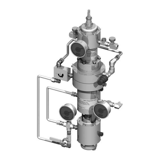
- Page 1 GE Oil & Gas Becker* VRP-SB-PID Series Natural Gas Controllers Instruction Manual GE Data Classification : Public...
- Page 2 REFERENCE INFORMATION IN ADDITION TO THE CUSTOMER/OPERATOR’S NORMAL OPERATION AND MAINTENANCE PROCEDURES. SINCE OPERATION AND MAINTENANCE PHILOSOPHIES VARY, GE (GENERAL ELECTRIC COMPANY AND ITS SUBSIDIARIES AND AFFILIATES) DOES NOT ATTEMPT TO DICTATE SPECIFIC PROCEDURES, BUT TO PROVIDE BASIC LIMITATIONS AND REQUIREMENTS CREATED BY THE TYPE OF EQUIPMENT PROVIDED.
-
Page 3: Table Of Contents
Diaghragm ......................... 50 O-Rings ......................... 51 Introduction Description GE’s Becker VRP-SB-PID series Natural Gas Controller The Becker VRP-SB-PID is a proportional-integral-derivative represents a breakthrough in pressure control technology for the controller. This concept will be further explained in the natural gas industry. Built to exacting specifications, this easily operations section of this manual. -
Page 4: Scope Of This Manual
PID = Proportional, Integral, Derivative Control Technical Assistance 40 = Maximum power gas Should you have any questions, please contact your local GE sales Each unit has a stainless steel control tag fastened under one representative or technical assistance at: of the bolts of the spring cartridge. - Page 5 1C and 1D represent the Top Balance Valve direction of gas flow. Bottom Balance Valve Figure 1 - Principles of Operation Direct Acting VRP-600-SB-PID-40 (High Gain) Yellow Spring 3 | GE Oil & Gas © 2016 General Electric Company. All rights reserved.
-
Page 6: Principles Of Operation
If the restriction is too great, the feedback delay will be too long and the system will become unstable. © 2016 General Electric Company. All rights reserved. Becker VRP-SB-PID Series Natural Gas Controllers Instruction Manual | 4... - Page 7 Pressure Derivative Integral Integral Output Output Feedback Module Exhaust Power Exhaust Output Block Valve Figure 2 - Direct Acting VRP-SB-PID Figure 3 - Reverse Acting VRP-SB-PID 5 | GE Oil & Gas © 2016 General Electric Company. All rights reserved.
-
Page 8: Control Spring Range Selection For Vrp-Sb-Pid Controllers
Output Range 12 psig = 0.522 Proportional Band 23 psig Output Range 30 psig - 6 psig = 24 psig (165 kPa) © 2016 General Electric Company. All rights reserved. Becker VRP-SB-PID Series Natural Gas Controllers Instruction Manual | 6... - Page 9 VRP-600-SB-PID-80, Low Gain (No Rings), Yellow Spring Controller Gain (K) Output Range 24 psig = 0.235 Proportional Band 102 psig Output Range 30 psig - 6 psig = 24 psig (165 kPa) 7 | GE Oil & Gas © 2016 General Electric Company. All rights reserved.
- Page 10 Output Range 30 psig = 0.235 Proportional Band 127.5 psig Output Range 30 psig - 6 psig = 24 psig (165 kPa) © 2016 General Electric Company. All rights reserved. Becker VRP-SB-PID Series Natural Gas Controllers Instruction Manual | 8...
-
Page 11: Conversion To Vrp-Sb-Pd Controller
Power gas is fed Block Valve Output into the integral Block Valve chamber Figure 4 - Direct Acting VRP-SB-PID Controller Figure 5 - Reverse Acting VRP-SB-PID Controller 9 | GE Oil & Gas © 2016 General Electric Company. All rights reserved. -
Page 12: Control Spring Range Selection For Vrp-Sb-Pd Controllers
1050-1500 psig 276psig (25-8073) (7584-10342 kPa) (7584-10342 kPa) (7239-10342 kPa) (1903 kPa) Note: Refer to motor information specified in Tables 3 and 4. © 2016 General Electric Company. All rights reserved. Becker VRP-SB-PID Series Natural Gas Controllers Instruction Manual | 10... -
Page 13: Pid-40, Pid-80, Pid-125 Explanations
At this point the gauge may increase to the maximum power gas very quickly. 11 | GE Oil & Gas © 2016 General Electric Company. All rights reserved. - Page 14 This should take 10-20 seconds if the integral valve is wide open, 90 psig respectively. and 1-2 minutes if it is at #7. © 2016 General Electric Company. All rights reserved. Becker VRP-SB-PID Series Natural Gas Controllers Instruction Manual | 12...
-
Page 15: Applications
The reset metering valve can be adjusted between 4 and 15 on the outer barrel. Four represents the smallest reset value (the slowest correction rate). 13 | GE Oil & Gas © 2016 General Electric Company. All rights reserved. -
Page 16: Power Plant Control Station With Start-Up/Trimming Regulator
This is accomplished by an inherent characteristic of the flexible element, and by a proportional only controller in the case of Globe valves. © 2016 General Electric Company. All rights reserved. Becker VRP-SB-PID Series Natural Gas Controllers Instruction Manual | 14... -
Page 17: Power Plant Station With Globe Style Control Valve
SPRING TO OPEN GLOBE VALVE WORKING REGULATOR MONITOR REGULATOR POWER GAS LINE JACKET LINE OUTPUT LINE SENSING LINE ALL LINES ARE SEPARATE, INTERSECTING LINES DO NOT IMPLY CONNECTIONS 15 | GE Oil & Gas © 2016 General Electric Company. All rights reserved. -
Page 18: Power Plant Station With T-Ball Style Control Valve
SPRING TO OPEN BALL VALVE MONITOR REGULATOR WORKING REGULATOR POWER GAS LINE OUTPUT LINE SENSING LINE ALL LINES ARE SEPARATE, INTERSECTING LINES DO NOT IMPLY CONNECTIONS © 2016 General Electric Company. All rights reserved. Becker VRP-SB-PID Series Natural Gas Controllers Instruction Manual | 16... -
Page 19: Power Plant Station With Globe Style Control Valve
SPRING TO CLOSE BALL VALVE WORKING REGULATOR MONITOR REGULATOR POWER GAS LINE OUTPUT LINE SENSING LINE ALL LINES ARE SEPARATE, INTERSECTING LINES DO NOT IMPLY CONNECTIONS 17 | GE Oil & Gas © 2016 General Electric Company. All rights reserved. -
Page 20: Power Plant Station With Globe Style Control Valve
SPRING TO OPEN GLOBE VALVE MONITOR REGULATOR WORKING REGULATOR OUTPUT PRESSURE SENSING PRESSURE ALL LINES ARE SEPARATE, INTERSECTING LINES DO NOT IMPLY CONNECTIONS © 2016 General Electric Company. All rights reserved. Becker VRP-SB-PID Series Natural Gas Controllers Instruction Manual | 18... -
Page 21: Fuel Regulator To Compressor Turbine
TO COMPRESSOR FLOW TURBINE SPRING TO CLOSE GLOBE VALVE SPRING TO OPEN GLOBE VALVE FIRST STAGE CUT REGULATOR SECOND STAGE CUT REGULATOR OUTPUT PRESSURE SENSING PRESSURE 19 | GE Oil & Gas © 2016 General Electric Company. All rights reserved. -
Page 22: Double Stage Cut With Working Monitor
TO COMPRESSOR FLOW TURBINE SPRING TO CLOSE GLOBE VALVE SPRING TO OPEN GLOBE VALVE WORKING MONITOR REGULATOR WORKING REGULATOR OUTPUT PRESSURE SENSING PRESSURE © 2016 General Electric Company. All rights reserved. Becker VRP-SB-PID Series Natural Gas Controllers Instruction Manual | 20... -
Page 23: Annual Maintenance Checklist
C. Shut of the supply pressure and bleed the system down at the pilot. D. Take careful note of derivative orifice settings and all connections of tubes and fittings. 21 | GE Oil & Gas © 2016 General Electric Company. All rights reserved. -
Page 24: Parts Lists And Part Numbers
95-2671 1/4-20 x 3" SHCS 98-3231 Inner Tube 30-7003 8-32 x 1/2" SHCS Alloy (1500 only) 98-3269 600-1000 Inner Tube Cap 30-7007 © 2016 General Electric Company. All rights reserved. Becker VRP-SB-PID Series Natural Gas Controllers Instruction Manual | 22... - Page 25 600 Top Space 30-7050 1/4" NPT Vent Elbow 01-2572 1/4" NPT Vent Elbow 01-2572 O-Ring-012 95-2615 Diaphragm w/Hole 30-7011 1/4" NPT Vent Elbow 01-2572 1000-1500 Top Spacer 30-7058 23 | GE Oil & Gas © 2016 General Electric Company. All rights reserved.
- Page 26 1/4 x 2 1/2" SHCS 98-3232 Small w/Hole 30-7010 PID Spring Spacer 30-7046 Fixed Spring 30-7054 Spring Nut SS 30-7048 Spring Support Plate 30-7047 © 2016 General Electric Company. All rights reserved. Becker VRP-SB-PID Series Natural Gas Controllers Instruction Manual | 24...
- Page 27 Lexan Cover 25-1034 Seat Spacer 35-1526 Adjusting Drum 35-1534 Seat Assembly 01-7082 Thrust Bearing 25-1062 8-32 x 1/2" SHCS 98-2614 1/4" NPT Bottom Body 35-1558 O-Ring-010 95-2609 25 | GE Oil & Gas © 2016 General Electric Company. All rights reserved.
- Page 28 3/8-16 x 3/4’ HHCS 98-2580 Spring Seat 11-2503 Spring Comp. Screw 30-7070 3/8 SS Lock Washer 98-2782 3/8 SS Flat Washer 98-2780 © 2016 General Electric Company. All rights reserved. Becker VRP-SB-PID Series Natural Gas Controllers Instruction Manual | 26...
-
Page 29: Accessories
The main supply valve is worn out or defective. VB-250 VB-250 Volume Booster Close-up From Power Actuator Power From Output Exhaust VRP-SB-PID Spring to Open Ball Valve (Direct Acting) 27 | GE Oil & Gas © 2016 General Electric Company. All rights reserved. -
Page 30: Assembly Manual
Seat Cover (E) and 2, 10-32 x 3/8” FHMS (F). Seat Cover (E) and 2, 10-32 x 3/8” FHMS (F). Figures 1, 2 and 3 © 2016 General Electric Company. All rights reserved. Becker VRP-SB-PID Series Natural Gas Controllers Instruction Manual | 28... - Page 31 Top Body (G) Soap test Pressurize here this port Pressurize this port Bottom Body (H) Bottom Body (H) Soap test here Soap test here Figure 5 29 | GE Oil & Gas © 2016 General Electric Company. All rights reserved.
-
Page 32: Top Body Piston Assembly
Piston (J) with 2, 8-32 x 1/2” SHCS (I). Piston (M) with 2, 8-32 x 1/2” SHCS (I). Figure 6 Figure 7 © 2016 General Electric Company. All rights reserved. Becker VRP-SB-PID Series Natural Gas Controllers Instruction Manual | 30... -
Page 33: Top Body Diaphragm Assembly
Outside Piston (J). Down Torque Nuts in Steps 25 and 26 to 140-160 in.-lbs. Convolute Convolute Convolute Down Convolute Down Orientation Figure 8 Figure 9 Convolute 31 | GE Oil & Gas © 2016 General Electric Company. All rights reserved. -
Page 34: Sensitivity Drum Assembly
Apply lube here. Confirm this orientation before pressfit! Figure 10 Figure 11 Use pistons J and O Step to turn assemblies. Step © 2016 General Electric Company. All rights reserved. Becker VRP-SB-PID Series Natural Gas Controllers Instruction Manual | 32... -
Page 35: Centering The Diaphragms
Diaphragm (R) as shown in Figure 14. STEP Figure 12 STEP STEP STEP STEP STEP STEP STEP Figure 13 Step Step Step Step Figure 14 33 | GE Oil & Gas © 2016 General Electric Company. All rights reserved. -
Page 36: Sensitivity Spacer Assembly
Make sure these numbers are aligned as shown in Figure 16, before the assembly is fastened together. Note: (2) Do not use for VRP-PID-125. GGGG GGGG Figure 16 © 2016 General Electric Company. All rights reserved. Becker VRP-SB-PID Series Natural Gas Controllers Instruction Manual | 34... -
Page 37: Bottom Cap Assembly
(DD) by fastening the Bottom Spring Cartridge (CC) to the Bottom Body(H) with 6, 1/4-20 x 3/4” HHCS (Z). Torque to 100-110 in.-lbs. Seat Orientation Figure 17 Figure 18 Figure 19 Seat Orientation Seat Orientation 35 | GE Oil & Gas © 2016 General Electric Company. All rights reserved. -
Page 38: Bracket Mounting
3/8-16 x 3/4 HHCS (FFFF). VRP-SB-PID-80 VRP-SB-PID-40 VRP-SB-PID-125 CCCC CCCC CCCC DDDD DDDD EEEE EEEE DDDD FFFF EEEE FFFF FFFF Figure 20 Figure 21 Figure 22 © 2016 General Electric Company. All rights reserved. Becker VRP-SB-PID Series Natural Gas Controllers Instruction Manual | 36... -
Page 39: Diaphragm Assembly #1
Aluminum Washer Nut (QQ). Make sure the Washer Nut (QQ) is secured tightly, with the undercut side facing the Diaphragm (PP). Torque to 100-110 in-lb. Figure 25 37 | GE Oil & Gas © 2016 General Electric Company. All rights reserved. -
Page 40: Spring Support Plate Assembly
Piston (J) of the Top Body (G), thereby compressing the spring. Spring Diaphragm Support Assembly Plate (RR) Orientation Serrated Surface Down Figure 26 Figure 27 Figure 28 © 2016 General Electric Company. All rights reserved. Becker VRP-SB-PID Series Natural Gas Controllers Instruction Manual | 38... - Page 41 Assembly Orientation Figure 29 Large Large Chamfer Chamfer Faces Faces Down Down Diaphragm Diaphragm Assembly Assembly Large Large Chamfer Chamfer Faces Faces Figure 30 Figure 31 39 | GE Oil & Gas © 2016 General Electric Company. All rights reserved.
-
Page 42: Spring Cartridge Assembly
(EEE) while holding it in a vise. Torque to 140-160 in.-lbs. Move to Step 52. CONVOLUTE DOWN HOLD WITH VISE Figure 32 HOLD WITH VISE Figure 33 Figure 34 © 2016 General Electric Company. All rights reserved. Becker VRP-SB-PID Series Natural Gas Controllers Instruction Manual | 40... - Page 43 NUT (P). Torque to 180-220 in.-lbs. Move to Step 52. CONVOLUTE PISTON HAS DOWN THREADED HOLE Figure 35 ADAPTER BLOCK (HHH) ORIENTATION FROM SIDE VIEW HOLD STEP WITH SERRATED VISE SIDE DOWN Figure 36 41 | GE Oil & Gas © 2016 General Electric Company. All rights reserved.
-
Page 44: Adjusting Screw Assembly
SHOULD BE TIGHTENED AGAINST EACH OTHER THE BOTTOM FACE OF THIS NUT(MMM) MUST BE FLUSH WITH THE BOTTOM OF THE ADJUSTING SCREW(JJJ). Figure 39 © 2016 General Electric Company. All rights reserved. Becker VRP-SB-PID Series Natural Gas Controllers Instruction Manual | 42... -
Page 45: Spring Chamber Assembly
10 O’CLOCK (PPP) ASSEMBLY 10:00 ORIENTATION FROM STEP 51A SIDE VIEW TOP VIEW DIAPHRAGM ASSEMBLY #1 FRONT VIEW Figure 41 ASSEMBLY FROM STEP 56A Figure 42 43 | GE Oil & Gas © 2016 General Electric Company. All rights reserved. - Page 46 ORIENTATION ASSEMBLY FROM STEP 51D SIDE VIEW TOP VIEW DIAPHRAGM ASSEMBLY #1 FRONT VIEW Figure 43 ASSEMBLY FROM STEP 56C Figure 44 © 2016 General Electric Company. All rights reserved. Becker VRP-SB-PID Series Natural Gas Controllers Instruction Manual | 44...
-
Page 47: Cap Assembly
Seal Neck (VVV). Thread the Seal Neck (VVV) into the Cartridge Cap (XXX or YYY). LUBRICATE ADJUSTING SCREW(JJJ) DDD or FFF Figure 45 Figure 46 Figure 47 45 | GE Oil & Gas © 2016 General Electric Company. All rights reserved. - Page 48 VRP-600-SB-PID or 12, 1/4-20 x 3/4” HHCS (Z) for a VRP-1000/1500-SB-PID. AAAA BBBB Figure 48 Figure 50 AAAA BBBB Figure 49 Figure 51 © 2016 General Electric Company. All rights reserved. Becker VRP-SB-PID Series Natural Gas Controllers Instruction Manual | 46...
-
Page 49: Appendix A - List Of Recommended Tools
5. Screwdrivers Philips head, standard 6. Soft blow hammer 7. O-ring pik 8. Pen (centering of diaphragm) 9. General assembly grease 10. 3/8” drive torque wrench 47 | GE Oil & Gas © 2016 General Electric Company. All rights reserved. -
Page 50: Appendix B - Parts Silhouettes
Appendix B - Parts Silhouettes Bolts and Washers 98-3231 98-3232 98-3230 98-3238 98-2614 98-3269 98-3237 98-2684 (316) SS (Alloy) 98-3181 98-3227 98-2761 © 2016 General Electric Company. All rights reserved. Becker VRP-SB-PID Series Natural Gas Controllers Instruction Manual | 48... -
Page 51: Washers And Nuts
Appendix B - Parts Silhouettes (Cont’d) Washers and Nuts 30-7053 30-7014 25-1016 30-7017 25-1065 98-2500 98-3056 98-3213 49 | GE Oil & Gas © 2016 General Electric Company. All rights reserved. -
Page 52: Diaghragm
Appendix B - Parts Silhouettes (Cont’d) Diaghragm 30-7011 25-1027 30-7032 © 2016 General Electric Company. All rights reserved. Becker VRP-SB-PID Series Natural Gas Controllers Instruction Manual | 50... -
Page 53: O-Rings
Appendix B - Parts Silhouettes (Cont’d) O-Rings 95-2670 95-2615 95-2609 95-2674 95-2672 95-2665 95-2671 51 | GE Oil & Gas © 2016 General Electric Company. All rights reserved. - Page 54 DIRECT SALES OFFICE LOCATIONS AUSTRALIA ITALY SOUTH AFRICA Brisbane: Phone: +39-081-7892-111 Phone: +27-11-452-1550 Phone: +61-7-3001-4319 Fax: +39-081-7892-208 Fax: +27-11-452-6542 Fax: +61-7-3001-4399 JAPAN SOUTH AND CENTRAL Perth: Tokyo AMERICA AND THE CARIBBEAN Phone: +61-8-6595-7018 Phone: +81-03-6871-9008 Phone: +55-12-2134-1201 Fax: +61 8 6595-7299 Fax: +81-03-6890-4620 Fax:...