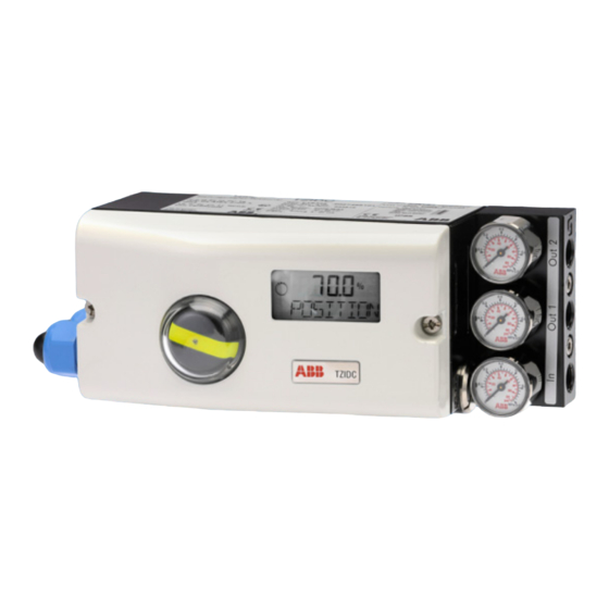
ABB TZIDC Commissioning Instructions
Electro-pneumatic positioner
for 4...20 ma two-wire technology,
hart, profibus pa,
foundation fieldbus
Hide thumbs
Also See for TZIDC:
- Operating instructions manual (88 pages) ,
- Commissioning instruction (60 pages) ,
- Manual (49 pages)

Related Manuals for ABB TZIDC


Summary of Contents for ABB TZIDC
- Page 1 Commissioning Instruction Electro-Pneumatic Positioner CI/TZIDC/110/120-EN TZIDC, TZIDC-110, TZIDC-120 For 4 ... 20 mA two-wire technology, HART, PROFIBUS PA, FOUNDATION fieldbus...
- Page 2 Fax: +49 621 381 931-29031 automation.service@de.abb.com © Copyright 2013 by ABB Automation Products GmbH Subject to changes without notice This document is protected by copyright. It assists the user in safe and efficient operation of the device. The contents of this document, whether whole or in part, may not be copied or reproduced without prior approval by the copyright holder.
-
Page 3: Table Of Contents
Cable entry ..............................24 "TZIDC with remote position sensor" ......................25 4.4.1 Electrical connection of TZIDC with remote position sensor ..............26 "TZIDC for remote position sensor" ......................27 4.5.1 Electrical connection of TZIDC for remote position sensor ..............28 ... - Page 4 Contents 7.1.8 FM Approvals ............................44 7.1.9 FM Control Document ........................... 45 TZIDC-110 ..............................49 7.2.1 ATEX Ex i .............................. 49 7.2.2 ATEX Ex n ............................. 50 7.2.3 IECEx ..............................51 ...
-
Page 5: Safety
Prior to using corrosive and abrasive materials for measurement purposes, the operator must check the level of resistance of all parts coming into contact with the materials to be measured. ABB Automation Products GmbH will gladly support you in selecting the materials, but cannot accept any liability in doing so. -
Page 6: Warranty Provisions
Failure to observe this safety information may result in damage to or destruction of the product and/or other system components. IMPORTANT (NOTE) This symbol indicates operator tips, particularly useful information, or important information about the product or its further uses. It does not indicate a dangerous or damaging situation. TZIDC, TZIDC-110, TZIDC-120 CI/TZIDC/110/120-EN... -
Page 7: Name Plate
Supplypress: 20 ... 90 psi Zuluftdruck: 1,4 ... 6 bar Input: analog 4 - 20 mA Eingang: ABB Automation Products GmbH D - 32425 Minden Made in Germany M00406 Fig. 1: Name plate 1 Complete model name 6... -
Page 8: Installation Safety Information
Incorrect parameter values can cause the valve to move unexpectedly. This can lead to process failures and result in injuries. Before recommissioning a TZIDC, TZIDC-110, TZIDC-120 positioner that was used at another location, the device must always be reset to factory settings. Never start Autoadjust before restoring factory settings. -
Page 9: 1.11 Returning Devices
Proper disposal prevents negative effects on people and the environment, and supports the reuse of valuable raw materials. If it is not possible to dispose of old equipment properly, ABB Service can accept and dispose of returns for a fee. CI/TZIDC/110/120-EN... -
Page 10: 1.13.2 Rohs Directive 2002/95/Ec
• Exception: The version of the TZIDC that is designed for operation with flammable gas, group IIA, temperature class T1 ((see IMPORTANT (NOTE) in 7 "Ex relevant specifications“ ). -
Page 11: Mounting
Incorrect parameter values can cause the valve to move unexpectedly. This can lead to process failures and result in injuries. Before recommissioning a TZIDC, TZIDC-110, TZIDC-120 positioner that was used at another location, the device must always be reset to factory settings. Never start Autoadjust before restoring factory settings. - Page 12 During installation make sure that the actuator travel or rotation angle for position feedback is implemented correctly. The maximum rotation angle for position feedback is 60° when installed on linear actuators and 120° on part-turn actuators. The minimum angle is always 25°. TZIDC, TZIDC-110, TZIDC-120 CI/TZIDC/110/120-EN...
-
Page 13: Mounting On Linear Actuators
Screw (1) and shim (2) for mounting to cast iron yoke • Two U-bolts (7) with two shims (8) and two nuts (9) for mounting to columnar yoke Required tools: Wrench, size 10 / 13 Allen key, size 4 CI/TZIDC/110/120-EN TZIDC, TZIDC-110, TZIDC-120... - Page 14 Attach the mount bracket (1) with screws (2) and shims (3) to the proper holes on the positioner housing. Tighten the screws as evenly as possible to ensure subsequent linearity. Align the mount bracket in the oblong hole to ensure that the operating range is symmetrical (lever moves between the arrows (4)) TZIDC, TZIDC-110, TZIDC-120 CI/TZIDC/110/120-EN...
- Page 15 Add the washers (4) and nuts (5). Hand tighten the nuts IMPORTANT (NOTE) Adjust the height of the positioner on the cast iron yoke or columnar yoke until the lever is horizontal (based on visual check) at half stroke of the valve. CI/TZIDC/110/120-EN TZIDC, TZIDC-110, TZIDC-120...
- Page 16 Adjust the actuator stroke to make use of as large an angle of rotation as possible (symmetrical around the center position). Recommended range for linear actuators: between -28 ... 28° Minimum angle: 25° IMPORTANT (NOTE) After mounting the unit check whether the positioner is operating within the sensor range. TZIDC, TZIDC-110, TZIDC-120 CI/TZIDC/110/120-EN...
-
Page 17: Mounting On Rotary Actuators
M6 (4), spring washers (3) and shim (2) to attach the mounting bracket (6) on the positioner • each four screws M5 (7), spring washers (8) and shim (9) to attach the mounting bracket on the actuator Required tools: Wrench, size 10 / 13 Allen key, size 3 CI/TZIDC/110/120-EN TZIDC, TZIDC-110, TZIDC-120... - Page 18 • Place the adapter in the proper position on the feedback shaft and fasten with set screws (3). One of the set screws must be locked in place on the flat side of the feedback shaft TZIDC, TZIDC-110, TZIDC-120 CI/TZIDC/110/120-EN...
- Page 19 2. Attach mounting bracket on the positioner Fig. 12 1 Mounting bracket 3. Attach positioner to the actuator Fig. 13 IMPORTANT (NOTE) After mounting the unit check whether the operating range for the actuator matches the sensor range on the positioner. CI/TZIDC/110/120-EN TZIDC, TZIDC-110, TZIDC-120...
-
Page 20: Electrical Connections
Electrical connections Electrical connections DANGER! Risk of explosion! (TZIDC only) It is prohibited to use the integrated communication interface (LKS) in an Ex area. Never use the integrated communication interface (LKS) on the mainboard with a positioner that is being used in an explosion risk area. - Page 21 Limit 1 Limit 2 M00767 Fig. 15: Remote sensor connection diagram A Basic device 1 Control unit B Options 2 Proximity switches 3 Microswitches IMPORTANT (NOTE) Keep cable shields as short as possible and connect on both sides. CI/TZIDC/110/120-EN TZIDC, TZIDC-110, TZIDC-120...
-
Page 22: Screw Terminal Assignments
3 Module for digital position feedback or terminals of 9 Grounding screw the shutdown module 4 Installation kit for digital position feedback, either proximity switches or 24 V microswitches 5 Same as 4 1) TZIDC only TZIDC, TZIDC-110, TZIDC-120 CI/TZIDC/110/120-EN... -
Page 23: Jumper Configuration On Mainboard (Tzidc-120 Only)
Electrical connections Jumper configuration on mainboard (TZIDC-120 only) M00494 Fig. 17 1 Simulation 2 Write access There are two jumpers on the mainboard that can be used to activate or block simulation mode and write access. Set the jumpers as shown below: M00495 Fig. -
Page 24: Cable Entry
- Cable: thread G 1/2, air pipe: thread Rc 1/4 As an option, one thread can be fitted with a cable gland and the other with a pipe plug if necessary. Fig. 19: Cable entry 1 Pipe plug 2 Cable gland TZIDC, TZIDC-110, TZIDC-120 CI/TZIDC/110/120-EN... -
Page 25: Tzidc With Remote Position Sensor
Electrical connections "TZIDC with remote position sensor" In the TZIDC designed with a remote position sensor, the components are accommodated in two housings, which together form one harmonized unit. Housing 1 (control unit) contains the electronics and pneumatics along with the following options (where applicable): •... -
Page 26: Electrical Connection Of Tzidc With Remote Position Sensor
Electrical connections 4.4.1 Electrical connection of TZIDC with remote position sensor TZIDC control unit TZIDC remote sensor M00759 Fig. 21 1 Analog position feedback 7 Binary output 2 Digital position feedback switch 1 8 Binary input 3 Digital position feedback switch 2... -
Page 27: Tzidc For Remote Position Sensor
Electrical connections "TZIDC for remote position sensor" With the TZIDC designed for remote position sensors, the positioner is supplied without position detection. The housing (control unit) contains the electronics and pneumatics along with the following options (where applicable): • Analog position feedback •... -
Page 28: Electrical Connection Of Tzidc For Remote Position Sensor
Electrical connections 4.5.1 Electrical connection of TZIDC for remote position sensor M00760 Fig. 23: TZIDC control unit 1 Analog position feedback 7 Binary output 2 Digital position feedback switch 1 8 Binary input 3 Digital position feedback switch 2 9 Setpoint input... -
Page 29: Pneumatic Connection
Pneumatic connection Pneumatic connection IMPORTANT (NOTE) The TZIDC, TZIDC-110, TZIDC-120 positioner must be supplied with instrument air that is free of oil, water and dust. The purity and oil content should meet the requirements of Class 3 according to DIN/ISO 8573-1. - Page 30 Join the pipe connections according to the following designation: Designation Pipe connection Supply air, pressure 1.4 ... 6 bar (20 ... 90 psi) OUT1 Actuating pressure for actuator OUT2 Actuating pressure for actuator (2nd connection with double-acting actuator) TZIDC, TZIDC-110, TZIDC-120 CI/TZIDC/110/120-EN...
-
Page 31: Commissioning
Autoadjust then runs again. IMPORTANT (NOTE) Autoadjust does not always result in optimum control conditions. 1) The zero position is determined automatically and saved during Autoadjust (counter-clockwise (CTCLOCKW) for linear actuators and clockwise (CLOCKW) for part-turn actuators). CI/TZIDC/110/120-EN TZIDC, TZIDC-110, TZIDC-120... -
Page 32: Operating Modes
1) Since self-optimization in operating mode 1.0 is subject to several factors during control operation with adaptation, incorrect adjustments could be made over an extended period. 2) Position not active 3) For high-speed mode: Press simultaneously TZIDC, TZIDC-110, TZIDC-120 CI/TZIDC/110/120-EN... -
Page 33: Tzidc-110 / Tzidc-120
Commissioning TZIDC-110 / TZIDC-120 bieten 1. Feed in pneumatic supply power 2. Connect the bus to the bus terminals with any polarity (or supply power 9 ... 32 V DC) ° is displayed 3. Check mount: • Press and hold down ;... -
Page 34: Operating Modes
° ° Manual adjustment in the operating range Adjust with conf conf ° ° Manual adjustment in the sensor range Adjust with conf conf 1) Positioning not active. 2) for high-speed mode: Press simultaneously. TZIDC, TZIDC-110, TZIDC-120 CI/TZIDC/110/120-EN... -
Page 35: Ex Relevant Specifications
-40 ... 35 °C. II 2 D Housing surface temperature Ambient temperature range (II 2 D) T81 °C -40 ... 70 °C T61 °C -40 ... 50 °C T51 °C -40 ... 40 °C CI/TZIDC/110/120-EN TZIDC, TZIDC-110, TZIDC-120... - Page 36 Ex ia or Ex ib type of ignition protection IIC: = 5mH = 2 µF IIB: = 5mH = 10 µF Local communication Only for connection to a programmer outside the potentially interface (LKS) explosive area. (See special conditions) TZIDC, TZIDC-110, TZIDC-120 CI/TZIDC/110/120-EN...
- Page 37 • When used with gases from group IIA and a temperature class of T1 for auxiliary power, the TZIDC positioner may only be used outdoors or inside sufficiently ventilated buildings. • The gas supplied must be kept sufficiently free of air and oxygen to prevent an ignitable atmosphere from forming.
-
Page 38: Atex Ex N
Only use suitable cable entries which meet the requirements of IEC 60079-15. • If the SJ2_S1N (NO) proximity switch is used, the positioner may only be operated at an ambient temperature range from -25 ... 85 °C. TZIDC, TZIDC-110, TZIDC-120 CI/TZIDC/110/120-EN... -
Page 39: Iecex
Intrinsic safety "i" or "n" type of protection Standards: IEC 60079-0:2011 IEC 60079-11:2011 IEC 60079-15:2010 Type and TZIDC Ex ia IIC or Ex ib IIC designation Temperature class Ambient temperature range -40 ... 85 °C -40 ... 85 °C -40 ... 40 °C -40 ... -
Page 40: Iecex I
7.1.4 IECEx i Electrical data for a TZIDC designated as Ex ia IIC or Ex ib IIC With the intrinsically safe Ex ib IIC or Ex ia IIC type of ignition protection, only for connection to a certified intrinsically safe circuit. -
Page 41: Iecex N
Switch output U = 11 V DC (terminal +83 / -84) The following modules may be operated with the TZIDC as an option: Plug-in module for digital position feedback U = 5 ... 11 V DC (terminal +51 / -52 or +41 / -42) Plug-in module for analog position feedback U = 10 ... - Page 42 Class I, Div 1, Groups A, B, C and D; Class II, Div 1, Groups E, F and G Class III, Enclosure Type 4X: Model TZIDC, P/N V18345-x0x2x2xx0x Intelligent Positioner intrinsically safe with entity parameters of: Terminals 11 / 12...
-
Page 43: Csa Certification Record
Class I, Div 1, Groups A, B, C and D; Class II, Div 1, Groups E, F, and G, Class III, Div 1, Enclosure Type 4X: Model TZIDC, P/N V18345-x0x2x2xx0x Intelligent Positioner Input rated 30 V DC; max.4 … 20 mA Output pressure Max. -
Page 44: Fm Approvals
Ex relevant specifications 7.1.8 FM Approvals TZIDC Positioner, Model V18345-a0b2c2de0f IS/I,II,III/1/ABCDEFG/T4 Ta = 85 °C – 901064/7/4; Enity; NI/I/2/ABCD/T4 Ta = 85 °C; S/II,III/2/FG/T4 Ta =85 °C; Type 4XMax Enity Parameters: Per Control Drawings a = Case/mounting – 1, 2, 3, 4 or 9 b = Input/communication port –... -
Page 45: Fm Control Document
Ex relevant specifications 7.1.9 FM Control Document CI/TZIDC/110/120-EN TZIDC, TZIDC-110, TZIDC-120... - Page 46 Ex relevant specifications TZIDC, TZIDC-110, TZIDC-120 CI/TZIDC/110/120-EN...
- Page 47 Ex relevant specifications CI/TZIDC/110/120-EN TZIDC, TZIDC-110, TZIDC-120...
- Page 48 Ex relevant specifications TZIDC, TZIDC-110, TZIDC-120 CI/TZIDC/110/120-EN...
-
Page 49: Tzidc-110
(terminal +85 / -86) = 3.7 nF negligibly small Mechanical digital feedback For max. values, see EC type examination test certificate (terminal limit1 +51 / -52 or number PTB 00 ATEX 2049 X limit2 +41 / -42) CI/TZIDC/110/120-EN TZIDC, TZIDC-110, TZIDC-120... -
Page 50: Atex Ex N
Only use suitable cable entries which meet the requirements of IEC 60079-15. • If the SJ2_S1N (NO) proximity switch is used, the positioner may only be operated at an ambient temperature range from -25 ... 85 °C. TZIDC, TZIDC-110, TZIDC-120 CI/TZIDC/110/120-EN... -
Page 51: Iecex
-40 ... 50 °C 7.2.4 IECEx i Electrical data for TZIDC-110 for ia/ib/ic designated as Ex i IIC T6 or T4 Gb With the intrinsically safe Ex i IIC type of ignition protection, only for connection to a certified FISCO... -
Page 52: Iecex N
Ex relevant specifications 7.2.5 IECEx n Electrical data for TZIDC-110 designated as Ex nA IIC T6 or T4 Gc Signal circuit U = 9 ... 32 V DC (terminal +11 / -12) I = 10.5 mA Mechanical digital feedback U = 5 ... 11 V DC... -
Page 53: Csa International
Class I, Div 2, Groups A, B, C and D; Class II, Div 2, Groups E, F, and G, Class III, Enclosure Type 4X: Model TZIDC-110, P/N V18346-x032x2xx0x Intelligent Positioner Input rated 32 V DC; max.15 mA (powered by a SELV... -
Page 54: Csa Certification Record
Class I, Div 1, Groups A, B, C and D; Class II, Div 1, Groups E, F, and G, Class III, Div 1, Enclosure Type 4X: Model TZIDC-110, P/N V18346-x032x2xx0x Intelligent Positioner Input rated 32 V DC; max. 15 mA (powered by a SELV... -
Page 55: Fm Approvals
Ex relevant specifications 7.2.8 FM Approvals TZIDC-110 Positioner, Model V18346-a032b2cd0e IS/I,II,III/1/ABCDEFG/T6,T5,T4 Ta = 40 °C, 55 °C, 85 °C-901265 Entity, FISCO Entity and FISCO Parameters Terminals Type Groups Parameters Vmax Imax +11 / -12 Entity 24 V 250 mA 1.2 W 2.8 nF... -
Page 56: Fm Control Document
Ex relevant specifications 7.2.9 FM Control Document TZIDC, TZIDC-110, TZIDC-120 CI/TZIDC/110/120-EN... -
Page 57: Tzidc-120
Ex relevant specifications CI/TZIDC/110/120-EN TZIDC, TZIDC-110, TZIDC-120... - Page 58 Ex relevant specifications TZIDC, TZIDC-110, TZIDC-120 CI/TZIDC/110/120-EN...
-
Page 59: Atex Ex I
(terminal +85 / -86) = 3.7 nF negligibly small Mechanical digital feedback For maximum values, see EC type examination test certificate (terminal limit1 +51 / -52 or number PTB 00 ATEX 2049 X limit2 +41 / -42) CI/TZIDC/110/120-EN TZIDC, TZIDC-110, TZIDC-120... -
Page 60: Atex Ex N
Only use suitable cable entries which meet the requirements of IEC 60079-15. • If the SJ2_S1N (NO) proximity switch is used, the positioner may only be operated at an ambient temperature range from -25 ... 85 °C. TZIDC, TZIDC-110, TZIDC-120 CI/TZIDC/110/120-EN... -
Page 61: Iecex
-40 … 50 °C 7.3.4 IECEx i Electrical data for TZIDC-110 for ia/ib/ic designated as Ex i IIC T6 or T4 Gb With the intrinsically safe Ex i IIC type of ignition protection, only for connection to a certified FISCO... -
Page 62: Iecex N
Ex relevant specifications 7.3.5 IECEx n Electrical data for TZIDC-120 designated as Ex nA IIC T6 or T4 Gc Signal circuit U = 9 ... 32 V DC (terminal +11 / -12) I = 11.5 mA Mechanical digital feedback U = 5 to 11 V DC... -
Page 63: Csa International
Class I, Div 2, Groups A, B, C and D; Class II, Div 2, Groups E, F, and G, Class III, Enclosure Type 4X: Model TZIDC-120, P/N V18347-x042x2xx0x Intelligent Positioner Input rated 32 V DC; max.15 mA (powered by a SELV... -
Page 64: Csa Certification Record
Class I, Div 1, Groups A, B, C and D; Class II, Div 1, Groups E, F, and G, Class III, Div 1, Enclosure Type 4X: Model TZIDC-120, P/N V18347-x042x2xx0x Intelligent Positioner Input rated 32 V DC; max. 15 mA (powered by a SELV... -
Page 65: Fm Approvals
Ex relevant specifications 7.3.8 FM Approvals TZIDC-120 Positioner, Model V18347-a042b2cd0e IS/I,II,III/1/ABCDEFG/T6,T5,T4 Ta = 40 °C, 55 °C, 85 °C-901265 Entity, FISCO Entity and FISCO Parameters Terminals Type Groups Parameters Vmax Imax +11 / -12 Entity 24 V 250 mA 1.2 W 2.8 nF... -
Page 66: Fm Control Document
Ex relevant specifications 7.3.9 FM Control Document TZIDC, TZIDC-110, TZIDC-120 CI/TZIDC/110/120-EN... - Page 67 Ex relevant specifications CI/TZIDC/110/120-EN TZIDC, TZIDC-110, TZIDC-120...
- Page 68 Ex relevant specifications TZIDC, TZIDC-110, TZIDC-120 CI/TZIDC/110/120-EN...
-
Page 69: Appendix
Identification for intended use in potentially explosive atmospheres according Protection ATEX directive (marking in addition to CE marking) IEC standards FM Approvals (US) CSA International (Canada) IMPORTANT (NOTE) All documentation, declarations of conformity and certificates are available in ABB's download area. www.abb.com/instrumentation CI/TZIDC/110/120-EN TZIDC, TZIDC-110, TZIDC-120... - Page 70 Appendix TZIDC, TZIDC-110, TZIDC-120 CI/TZIDC/110/120-EN...
- Page 71 Which substances have come into contact with the device? We hereby state that the devices / components shipped have been cleaned and are free from any dangerous or poisonous substances. Town/city, date Signature and company stamp CI/TZIDC/110/120-EN TZIDC, TZIDC-110, TZIDC-120...
- Page 72 ABB has Sales & Customer Support expertise in over The Company’s policy is one of continuous product 100 countries worldwide. improvement and the right is reserved to modify the information contained herein without notice. www.abb.com/instrumentation Printed in the Fed. Rep. of Germany (03.2013) ©...