ABB TZIDC Manual
Hide thumbs
Also See for TZIDC:
- Operating instructions manual (88 pages) ,
- Commissioning instructions (72 pages) ,
- Commissioning instruction (60 pages)
Table of Contents
Advertisement
Quick Links
—
A B B M E A S U R E M E N T & A N A L Y T I C S | C O M M I S S I O N I N G I N S T R U C T I O N | C I / T Z I D C / A T E X / I E C E X - E N R E V . C
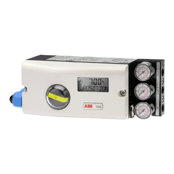
TZIDC
Digital Positioner
Introduction
—
TZIDC
The TZIDC is an intelligent digital positioner for
communication via HART within the positioner
product range. Unsurpassed shock absorption and
vibration compensation from 10 g to 80 Hz
distinguishes the TZIDC from other products and
guarantees reliable operation in nearly any area
under the harshest ambient conditions.
Non-Ex / ATEX / IECEx
Digital Positioner for the
positioning of pneumatically
controlled final control elements.
Additional Information
Additional documentation on TZIDC is available for
download free of charge at
www.abb.com/positioners.
Alternatively simply scan this code:
Advertisement
Table of Contents

Related Manuals for ABB TZIDC


Summary of Contents for ABB TZIDC
- Page 1 Introduction Additional Information — TZIDC The TZIDC is an intelligent digital positioner for Additional documentation on TZIDC is available for communication via HART within the positioner download free of charge at product range. Unsurpassed shock absorption and www.abb.com/positioners.
-
Page 2: Table Of Contents
Electrical data for inputs and outputs ......21 Connection on the device ..........23 Connection on device - TZIDC Control Unit with TZIDC Remote Sensor ..............25 Connection on device - TZIDC Control Unit for remote position sensor ..............26 ... -
Page 3: Safety
TZIDC DIGITAL POSITIONER | CI/TZIDC/ATEX/IECEX-EN REV. C Change from one to two columns 1 Safety General information and instructions Warnings The warnings in these instructions are structured as follows: These instructions are an important part of the product and must be retained for future reference. -
Page 4: Intended Use
/ or theft of data or information. ABB Automation Products GmbH and its affiliates are not liable for damages and / or losses related to such security breaches, any unauthorized access, interference, intrusion, leakage and / or theft of data or information. -
Page 5: Use In Potentially Explosive Atmospheres
The electric circuits of the positioner must be put into operation in all zones by persons qualified in accordance The TZIDC is approved for proper and intended use only. In case with TRBS 1203. The details on the type label are of non-compliance, the warranty and manufacturer’s liability do... -
Page 6: Maintenance, Repair
TZIDC DIGITAL POSITIONER | CI/TZIDC/ATEX/IECEX-EN REV. C … 2 Use in potentially explosive atmospheres Maintenance, repair Definition of terms according to IEC 60079-17: • Maintenance and exchange work may be conducted by Maintenance qualified specialists only, i.e., qualified personnel in Defines a combination of actions performed to maintain or accordance with TRBS 1203 or similar. -
Page 7: Product Identification
TZIDC DIGITAL POSITIONER | CI/TZIDC/ATEX/IECEX-EN REV. C Product identification Depending on the type of explosion protection, Ex-marking is Cable gland attached to the positioner on the right, next to the main name Limited temperature range of the M20 × 1.5 plastic cable gland plate. -
Page 8: Atex / Eac Tr-Cu-012
= 5 mH = 10 μF Local communication Only for connection to a programming device interface (LCI) using an ABB LCI adapter (Um ≤ 30 V DC) outside the hazardous area. Special conditions • Prevent electrostatic charging due to propagating brush discharge when the equipment is used for applications involving combustible dust. -
Page 9: Iecex Ex I
= 320 mA = negligibly small = 500 mW Local communication Only for connection to a programming device using interface (LCI) an ABB LCI adapter (Um ≤ 30 V DC) outside the hazardous area. Change from two to one column... -
Page 10: Product Identification
TZIDC DIGITAL POSITIONER | CI/TZIDC/ATEX/IECEX-EN REV. C 3 Product identification Name plate 1 Full type designation 8 Supply air pressure 2 Master number 9 Input signal 3 Hardware rev. j Mode of action of the pneumatic system 4 Software rev. -
Page 11: Transport And Storage
All devices delivered to ABB must be free from any hazardous materials (acids, alkalis, solvents, etc.). Please contact Customer Center Service acc. to page 4 for... -
Page 12: Installation
TZIDC DIGITAL POSITIONER | CI/TZIDC/ATEX/IECEX-EN REV. C 5 Installation Safety instructions External position sensors CAUTION Risk of injury due to incorrect parameter values! Incorrect parameter values can cause the valve to move unexpectedly. This can lead to process failures and result in injuries. -
Page 13: Mechanical Mounting
The electrical connection is performed as described in Connection on device - TZIDC Control Unit for remote position sensor on page 26. Note To connect the TZIDC Remote Sensor, a cable with the following specifications needs to be used: Figure 4: Operating range ²... -
Page 14: Mounting On Linear Actuators
TZIDC DIGITAL POSITIONER | CI/TZIDC/ATEX/IECEX-EN REV. C … 5 Installation … Mechanical mounting Operating range of rotary actuators: The usable span is 90°, which must be entirely within the measuring range, but does not necessarily need to run symmetrically to the longitudinal axis. - Page 15 TZIDC DIGITAL POSITIONER | CI/TZIDC/ATEX/IECEX-EN REV. C 5. Secure the mount bracket with screws and washers Note using the relevant tap holes on the positioner housing. Adjust the height of the positioner on the cast iron yoke or Tighten the screws as evenly as possible to ensure columnar yoke until the lever is horizontal (based on a visual subsequent linearity.
-
Page 16: Mounting On Rotary Actuator
TZIDC DIGITAL POSITIONER | CI/TZIDC/ATEX/IECEX-EN REV. C … 5 Installation … Mechanical mounting Position of actuator bolt Mounting on rotary actuator The actuator bolt for moving the potentiometer lever can be For mounting on part-turn actuators in accordance with mounted permanently on the lever itself or on the valve stem. - Page 17 TZIDC DIGITAL POSITIONER | CI/TZIDC/ATEX/IECEX-EN REV. C 1 Attachment bracket Figure 16: Screwing the attachment bracket onto the positioner Figure 15: Mounting the adapter on the positioner 1. Determine the mounting position (parallel to actuator or at 90° angle) 2. Calculate the rotational direction of the actuator (right or left).
-
Page 18: Electrical Connections
TZIDC DIGITAL POSITIONER | CI/TZIDC/ATEX/IECEX-EN REV. C … 5 Installation Electrical connections Safety instructions DANGER Risk of explosion for devices with local communication interface (LCI) A local communication interface (LCI) may not be operated in hazardous areas. • Never use the local communication interface (LCI) on the... -
Page 19: Positioner / Tzidc Control Unit Electrical Connection
TZIDC DIGITAL POSITIONER | CI/TZIDC/ATEX/IECEX-EN REV. C Positioner / TZIDC Control Unit Electrical Connection A Basic device C Connection TZIDC Remote Sensor / remote position sensor (only for TZIDC Control Unit version) B Options D Options, limit value monitor with proximity switches or microswitches... -
Page 20: Tzidc Remote Sensor Electrical Connection
41 / 42 / 43 Microswitches Limit 1 (Option) 51 / 52 / 53 Microswitches Limit 2 (Option) Note The TZIDC Remote Sensor can be fitted either with proximity switches or microswitches as limit switches. It is not possible to combine both variants. -
Page 21: Electrical Data For Inputs And Outputs
TZIDC DIGITAL POSITIONER | CI/TZIDC/ATEX/IECEX-EN REV. C Electrical data for inputs and outputs Binary output Output configurable as alarm output by software. Note When using the device in potentially explosive atmospheres, Binary output DO note the additional connection data in Use in potentially Terminals +83 / −84... - Page 22 TZIDC DIGITAL POSITIONER | CI/TZIDC/ATEX/IECEX-EN REV. C … 5 Installation … Electrical connections Limit monitor with proximity switches Limit 1, Limit 2 Module for digital feedback SW1, SW2* Terminals +41 / −42, +51 / −52 Terminals +41 / −42, +51 / −52...
-
Page 23: Connection On The Device
TZIDC DIGITAL POSITIONER | CI/TZIDC/ATEX/IECEX-EN REV. C Connection on the device 1 Cable gland 4 Terminal attachment kit for digital feedback 2 Blind plug 5 Terminals for basic unit 3 Terminals for option modules Figure 20: Connection to device (example) Change from one to two columns 2 tap holes ½- 14 NPT or M20 ×... - Page 24 TZIDC DIGITAL POSITIONER | CI/TZIDC/ATEX/IECEX-EN REV. C … 5 Installation … Electrical connections Wire cross-sectional areas Basic device Option modules Electrical connections Cross section 4 to 20 mA input Screw terminals max. 2.5 mm (AWG14) Rigid / flexible wires 0.14 to 1.5 mm...
-
Page 25: Connection On Device - Tzidc Control Unit With Tzidc Remote Sensor
TZIDC Control Unit Electrical Connection on page 19. If necessary, the following options can be installed if required: • If the TZIDC Control Unit is fastened so that it is it non- • Optical position indicator conductive, the housing must be grounded (TZIDC Control •... -
Page 26: Connection On Device - Tzidc Control Unit For Remote Position Sensor
Positioner / TZIDC Control Unit Electrical Connection on page 19. • If the TZIDC Control Unit is fastened such that it is it non- conductive, the housing must be grounded (TZIDC Control Unit and remote position sensor housing with the same electric potential);... -
Page 27: Pneumatic Connections
TZIDC DIGITAL POSITIONER | CI/TZIDC/ATEX/IECEX-EN REV. C Pneumatic connections Connection on the device Note The positioner must only be supplied with instrument air that is free of oil, water, and dust. The purity and oil content must meet the requirements of Class 3 in accordance with DIN/ISO 8573-1. -
Page 28: Air Supply
TZIDC DIGITAL POSITIONER | CI/TZIDC/ATEX/IECEX-EN REV. C … 5 Installation 6 Commissioning … Pneumatic connections Note The electrical power supply and supply air pressure data Air supply indicated on the name plate must be complied with during commissioning. Instrument air*... -
Page 29: Operating Modes
TZIDC DIGITAL POSITIONER | CI/TZIDC/ATEX/IECEX-EN REV. C Operating modes Standard automatic adjustment Selection from the operating level Note 1. Press and hold down MODE. Standard Auto Adjust does not always result in optimum control 2. Also press and release rapidly as often as required. The conditions. -
Page 30: Sample Parameters
TZIDC DIGITAL POSITIONER | CI/TZIDC/ATEX/IECEX-EN REV. C … 6 Commissioning Sample parameters ‘Change the zero position of the LCD display from clockwise (CLOCKW) to counter-clockwise limit stop (CTCLOCKW)’ Initial situation: the positioner is in bus operation on the 4. Changing parameter settings: operating level. -
Page 31: Setting The Mechanical Limit Switch With Proximity Switches
TZIDC DIGITAL POSITIONER | CI/TZIDC/ATEX/IECEX-EN REV. C Setting the mechanical limit switch with proximity Setting the mechanical limit switch with 24 V switches microswitches 1. Loosen the screws for the housing cover and remove it. 1. Loosen the screws for the housing cover and remove it. -
Page 32: Operation
TZIDC DIGITAL POSITIONER | CI/TZIDC/ATEX/IECEX-EN REV. C 7 Operation Safety instructions CAUTION Value display with unit This 7-segment display with four digits indicates parameter Risk of injury due to incorrect parameter values! values or parameter reference numbers. For values, the physical Incorrect parameter values can cause the valve to move unit (°C, %, mA) is also displayed. -
Page 33: Menu Levels
TZIDC DIGITAL POSITIONER | CI/TZIDC/ATEX/IECEX-EN REV. C Operating button functions Menu levels The positioner has two operating levels. Operating level Control button Meaning On the operating level the positioner operates in one of four ENTER • Acknowledge message possible operating modes (two for automatic control and •... -
Page 34: Maintenance
TZIDC DIGITAL POSITIONER | CI/TZIDC/ATEX/IECEX-EN REV. C 8 Maintenance 10 Additional documents The positioner does not require any maintenance if it is used as Note intended under normal operating conditions. All documentation, declarations of conformity and certificates are available in ABB's download area. -
Page 35: Appendix
TZIDC DIGITAL POSITIONER | CI/TZIDC/ATEX/IECEX-EN REV. C Change from two to one column 11 Appendix Return form Statement on the contamination of devices and components Repair and/or maintenance work will only be performed on devices and components if a statement form has been completed and submitted. - Page 36 We reserve the right to make technical changes or modify the contents of this document without prior notice. With regard to purchase orders, the agreed particulars shall prevail. ABB does not accept any responsibility whatsoever for potential errors or possible lack of information in this document.