ABB TZIDC Manual
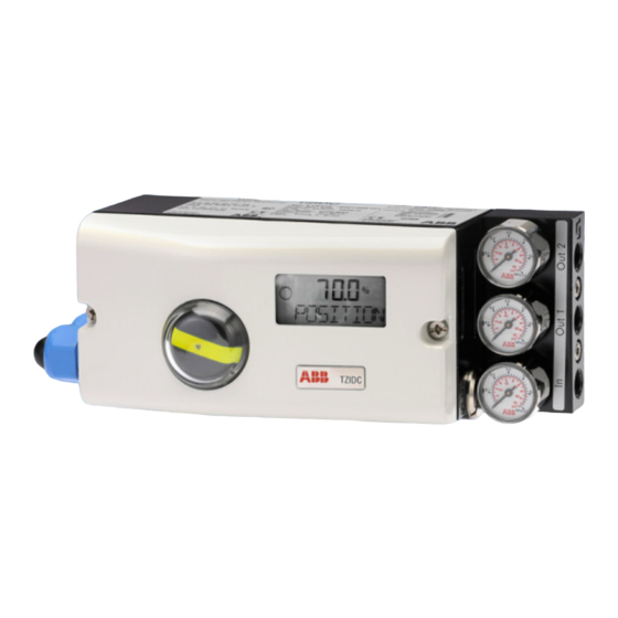
Digital positioner for the positioning of pneumatically controlled actuators
Hide thumbs
Also See for TZIDC:
- Operating instructions manual (88 pages) ,
- Commissioning instructions (72 pages) ,
- Commissioning instruction (60 pages)
Table of Contents
Advertisement
—
ABB MEASUREMENT & ANALYTICS | CONFIGURATION-, PARAMETERIZATION INSTRUCTION | COI/TZIDC/TZIDC-200-EN REV. B
TZIDC, TZIDC-200
Digital positioner
—
Introduction
TZIDC
TZIDC-200
Intelligent digital positioner builds the link
between the control system and the valve. Digital
positioners from ABB make an automatic
adjustment to shorten commissioning time, while
an adaptation program guarantees optimal
control of the position until the set point is
reached.
Digital positioner for the
positioning of pneumatically
controlled actuators.
Additional Information
Additional documentation on TZIDC, TZIDC-200 is
available for download free of charge at
www.abb.com/positioners.
Alternatively simply scan this code:
Advertisement
Table of Contents

Related Manuals for ABB TZIDC


Summary of Contents for ABB TZIDC
- Page 1 — ABB MEASUREMENT & ANALYTICS | CONFIGURATION-, PARAMETERIZATION INSTRUCTION | COI/TZIDC/TZIDC-200-EN REV. B TZIDC, TZIDC-200 Digital positioner Digital positioner for the positioning of pneumatically controlled actuators. — Introduction Additional Information TZIDC TZIDC-200 Intelligent digital positioner builds the link Additional documentation on TZIDC, TZIDC-200 is between the control system and the valve.
-
Page 2: Table Of Contents
TZIDC, TZIDC-200 DIGITAL POSITIONER | COI/TZIDC/TZIDC-200-EN REV. B Table of contents Safety ................4 Parameter group 4: Messages ..........22 General information and instructions ........4 TIME_OUT – stroke time monitoring ......22 Warnings ..................4 POS_SW1 – switching point SW1 ........22 Intended use ................ - Page 3 TZIDC, TZIDC-200 DIGITAL POSITIONER | COI/TZIDC/TZIDC-200-EN REV. B Parameter group 9: Digital output........34 ALRM_LOG – Alarm output logic ........34 SW1_LOG – Logic ............... 34 SW2_LOG – Logic ............... 35 ALARM DO – Logic ............. 35 EXIT – Back to work level ..........35 Parameter group 10: Digital input ........
-
Page 4: Safety
TZIDC, TZIDC-200 DIGITAL POSITIONER | COI/TZIDC/TZIDC-200-EN REV. B 1 Safety General information and instructions Intended use These instructions are an important part of the product and Positioning of pneumatically controlled actuators; designed for must be retained for future reference. mounting on linear and rotary actuators. -
Page 5: Cyber Security Disclaimer
Customer service center leakage and/or theft of data or information. Tel: +49 180 5 222 580 ABB and its affiliates are not liable for damages and/or losses Email: automation.service@de.abb.com related to such security breaches, any unauthorized access, interference, intrusion, leakage and/or theft of data or information. -
Page 6: Operation
TZIDC, TZIDC-200 DIGITAL POSITIONER | COI/TZIDC/TZIDC-200-EN REV. B 2 Operation Safety instructions Description of symbols CAUTION Risk of injury due to incorrect parameter values! Symbol Description Incorrect parameter values can cause the valve to move Operation or access is restricted. -
Page 7: Menu Levels
TZIDC, TZIDC-200 DIGITAL POSITIONER | COI/TZIDC/TZIDC-200-EN REV. B Menu levels Operating modes Operating mode 1.0: Control with adaptation The positioner has two operating levels. Operating level On the operating level the positioner operates in one of four possible operating modes (two for automatic control and two for manual mode). -
Page 8: Operating Mode 1.2: Manual Adjustment In The Stroke Range
TZIDC, TZIDC-200 DIGITAL POSITIONER | COI/TZIDC/TZIDC-200-EN REV. B … 2 Operation … Operating modes In both control modes 1.0 and 1.1, several values can be Operating mode 1.2: Manual adjustment in the stroke displayed besides the current actuator position: range Setpoint display The valve is adjusted manually using the direction buttons ... -
Page 9: Locks
TZIDC, TZIDC-200 DIGITAL POSITIONER | COI/TZIDC/TZIDC-200-EN REV. B Locks Positioner operation can be inhibited completely or partially via the digital input and the FUNCTION parameter in parameter group 10 (DIG_IN (digital input)). This allows the user to prevent or restrict operating actions of unauthorized personnel as desired. -
Page 10: Configuration
TZIDC, TZIDC-200 DIGITAL POSITIONER | COI/TZIDC/TZIDC-200-EN REV. B 3 Configuration General information Most parameters for the positioner can be set locally, meaning Designator Name that configuration only needs to be performed via the local P1._ STANDARD Standard communication interface (LCI) or FSK modem and PC in P2._... -
Page 11: Parameter Description Hart
TZIDC, TZIDC-200 DIGITAL POSITIONER | COI/TZIDC/TZIDC-200-EN REV. B Parameter description HART® Parameter Display Function Possible parameter setting Unit Factory setting P1._ STANDARD P1.0 ACTUATOR Actuator type Actuator type LINEAR, ROTARY LINEAR P1.1 AUTO_ADJ Auto adjust Autoadjust Function P1.2 ADJ_MODE Auto adjust mode... - Page 12 TZIDC, TZIDC-200 DIGITAL POSITIONER | COI/TZIDC/TZIDC-200-EN REV. B … 3 Configuration … Parameter description HART® Parameter Display Function Possible parameter setting Unit Factory setting P6._ MAN_ADJ P6.0 MIN_VR Min. valve range Operating range, min. 0.0 to 100.0 P6.1 MAX_VR Max. valve range Operating range, max.
- Page 13 TZIDC, TZIDC-200 DIGITAL POSITIONER | COI/TZIDC/TZIDC-200-EN REV. B Parameter Display Function Possible parameter setting Unit Factory setting P8._ ANLG_OUT P8.0 MIN_RGE Min. range Min. current range 4.0 to 18.4 P8.1 MAX_RGE Max. range Max. current range 20.0 to 5.7 20.0 P8.2...
-
Page 14: Hart Parameter Overview (Graphic)
TZIDC, TZIDC-200 DIGITAL POSITIONER | COI/TZIDC/TZIDC-200-EN REV. B … 3 Configuration HART parameter overview (graphic) Figure 2: HART® Parameter Overview... -
Page 15: Parametergroup 1: Standard
TZIDC, TZIDC-200 DIGITAL POSITIONER | COI/TZIDC/TZIDC-200-EN REV. B Parametergroup 1: Standard To start the Autoadjust, press and hold ENTER until the countdown from 3 to 0 is finished. During the countdown, the automatic adjustment mode selected with the ADJ_MODE parameter is displayed. While Autoadjust is running, the control loop symbol flashes in the display, and the current state of Autoadjust is indicated with the messages listed below. -
Page 16: Adj_Mode - Automatic Adjustment Mode
TZIDC, TZIDC-200 DIGITAL POSITIONER | COI/TZIDC/TZIDC-200-EN REV. B … 3 Configuration … Parametergroup 1: Standard ADJ_MODE – Automatic adjustment mode Once Autoadjust has finished running without encountering any errors, the device displays the message "RUN" in the bottom line and a code number in the top line, indicating the step that is currently being executed: Air is completely evacuated from actuator (OUT1). -
Page 17: Find_Dev - Find Device
TZIDC, TZIDC-200 DIGITAL POSITIONER | COI/TZIDC/TZIDC-200-EN REV. B Parameter group 2: Set point FIND_DEV – find device MIN_RGE – min. set point range This function is only available with HART®7 and enables the affected device to be identified in the system. -
Page 18: Charact - Characteristic Curve
TZIDC, TZIDC-200 DIGITAL POSITIONER | COI/TZIDC/TZIDC-200-EN REV. B … 3 Configuration … Parameter group 2: Set point CHARACT – characteristic curve SHUT_CLS – Shut-off value 0 % Use this parameter to select a function that adjusts the behavior The shut-off value SHUT_CLS is a percentage of the operating... -
Page 19: Ramp Up - Set Point Ramp (Up)
TZIDC, TZIDC-200 DIGITAL POSITIONER | COI/TZIDC/TZIDC-200-EN REV. B Note RAMP UP – set point ramp (up) To display the stroke time (stroke time up), press and hold the ENTER button. Here the stroke time for the actuator can be increased. A setpoint change is not directly transferred to the positioner;... -
Page 20: Parameter Group 3: Working Range
TZIDC, TZIDC-200 DIGITAL POSITIONER | COI/TZIDC/TZIDC-200-EN REV. B … 3 Configuration Parameter group 3: Working range MAX_RGE – max. operating range MIN_RGE – min. operating range The working range can be configured to be smaller than the maximum mechanical working range. -
Page 21: Zero_Pos - Zero Point Position
TZIDC, TZIDC-200 DIGITAL POSITIONER | COI/TZIDC/TZIDC-200-EN REV. B ZERO_POS – zero point position EXIT – Back to work level With this parameter you can assign the zero position of the With this parameter you can leave the configuration level. The display to the zero position of the valves and fittings. -
Page 22: Parameter Group 4: Messages
TZIDC, TZIDC-200 DIGITAL POSITIONER | COI/TZIDC/TZIDC-200-EN REV. B … 3 Configuration Parameter group 4: Messages POS_SW1 – switching point SW1 TIME_OUT – stroke time monitoring With this parameter you can define the switching point SW1 as a percentage of the operating range. -
Page 23: Sw1_Actv - Active Direction Sw1
TZIDC, TZIDC-200 DIGITAL POSITIONER | COI/TZIDC/TZIDC-200-EN REV. B SW1_ACTV – Active Direction SW1 EXIT – Back to work level With this parameter you define whether a message is to be With this parameter you can leave the configuration level. The triggered for exceeding or falling below switching point SW1. -
Page 24: Parameter Group 5: Alarms
TZIDC, TZIDC-200 DIGITAL POSITIONER | COI/TZIDC/TZIDC-200-EN REV. B … 3 Configuration Parameter group 5: Alarms SENS_RGE – operating range up-scaled Note Active alarms are signaled at the digital output and using the With this parameter you can determine that an alarm is signaled "Analog feedback"... -
Page 25: Time_Out - Stroke Time Monitoring
TZIDC, TZIDC-200 DIGITAL POSITIONER | COI/TZIDC/TZIDC-200-EN REV. B TIME_OUT – stroke time monitoring TRAVEL – travel counter Use this parameter to activate the "Dead band time limit" With this parameter you can determine that an alarm is signaled function. when the travel counter exceeds the specified limit value. The limit value is edited remotely via PC. -
Page 26: Parameter Group 6: Manual Adjustment
TZIDC, TZIDC-200 DIGITAL POSITIONER | COI/TZIDC/TZIDC-200-EN REV. B … 3 Configuration Parameter group 6: Manual adjustment MAX_VR – max. operating range MIN_VR - min. working range Normally, the operating range is determined automatically during Autoadjust. A partial run of automatic adjustment that is... -
Page 27: Actuator - Actuator Type
TZIDC, TZIDC-200 DIGITAL POSITIONER | COI/TZIDC/TZIDC-200-EN REV. B ACTUATOR – actuator type DANG_DN – Dead Angle Close With this parameter you can configure the positioner for Use this parameter to cut off the unusable range of the valve operation on a linear actuator (sensor range ±30°) or on a part- flow characteristic curve from the point of view of control. -
Page 28: Exit - Back To Work Level
TZIDC, TZIDC-200 DIGITAL POSITIONER | COI/TZIDC/TZIDC-200-EN REV. B … 3 Configuration Parameter group 7: Controller parameters … Parameter group 6: Manual adjustment EXIT – Back to work level KP UP – KP value (up) With this parameter you can leave the configuration level. The positioner returns to the operating level. -
Page 29: Kp Dn - Kp Value (Down)
TZIDC, TZIDC-200 DIGITAL POSITIONER | COI/TZIDC/TZIDC-200-EN REV. B KP DN – KP value (down) The TV value is the derivative time of the controller. The control speed and stability are affected by the TV value in such a way that it counteracts the KP value dynamically. The control speed decreases as the TV value increases. -
Page 30: Y-Ofs Up - Y Offset (Up)
TZIDC, TZIDC-200 DIGITAL POSITIONER | COI/TZIDC/TZIDC-200-EN REV. B … 3 Configuration … Parameter group 7: Controller parameters Y-OFS UP – Y offset (up) Y-OFS DN – Offset (down) Note Note In the case of most actuators, all control parameters can be In the case of most actuators, all control parameters can be optimized by using Auto Adjust. -
Page 31: Tol_Band - Tolerance Band
TZIDC, TZIDC-200 DIGITAL POSITIONER | COI/TZIDC/TZIDC-200-EN REV. B TOL_BAND – Tolerance band TEST – Test The "tolerance band" (TOL_BAND) defines a ± range around the The test is used to activate the controller, and you can check the position setpoint. When the position of the valves and fittings effects of the changes to this parameter group, e.g., by... -
Page 32: Leak_Sen - Leak Sensitivity
TZIDC, TZIDC-200 DIGITAL POSITIONER | COI/TZIDC/TZIDC-200-EN REV. B … 3 Configuration Parameter group 8: Analog output … Parameter group 7: Controller parameters (on the plug-in module for analog feedback) LEAK_SEN – Leak Sensitivity MIN_RGE – Current range min. Determination of a possible leakage between the output positioner and the pneumatic actuator. -
Page 33: Alarm - Alarm
TZIDC, TZIDC-200 DIGITAL POSITIONER | COI/TZIDC/TZIDC-200-EN REV. B ALARM – Alarm TEST – Test When an alarm / message is generated in the positioner, it is Test is for simulation of the analog output. The test allows you signaled via the digital and analog outputs. You can use the... -
Page 34: Exit - Back To Work Level
TZIDC, TZIDC-200 DIGITAL POSITIONER | COI/TZIDC/TZIDC-200-EN REV. B … 3 Configuration Parameter group 9: Digital output … Parameter group 8: Analog output EXIT – Back to work level ALRM_LOG – Alarm output logic With this parameter you can leave the configuration level. The Note positioner returns to the operating level. -
Page 35: Sw2_Log - Logic
TZIDC, TZIDC-200 DIGITAL POSITIONER | COI/TZIDC/TZIDC-200-EN REV. B SW2_LOG – Logic EXIT – Back to work level You can use this parameter to define the active state for switch With this parameter you can leave the configuration level. The output SW2 (on the plug-in module for digital feedback). -
Page 36: Parameter Group 10: Digital Input
TZIDC, TZIDC-200 DIGITAL POSITIONER | COI/TZIDC/TZIDC-200-EN REV. B … 3 Configuration Parameter group 10: Digital input Note The lock CNF_LOCK, OP_LOCK or ALL_LOCK is displayed only if the voltage is connected to the digital input. CNF_LOCK Local access to the configuration level is inhibited. However, FUNCTION –... -
Page 37: Exit - Back To Work Level
TZIDC, TZIDC-200 DIGITAL POSITIONER | COI/TZIDC/TZIDC-200-EN REV. B Parameter group 11: Safety position EXIT – Back to work level FAIL_POS – Safety position With this parameter you can leave the configuration level. The positioner returns to the operating level. Here you can either save data in the non-volatile memory or discard all previously made changes (also the changes in other parameter groups). -
Page 38: Fact_Set - Factory Setting
Press and hold the ENTER button, until the countdown displayed on it has run from 3 to 0 and finished. This function is reserved for use by ABB Service only. The positioner is reset to the factory settings. The message COMPLETE is displayed. -
Page 39: Hart_Rev - Hart® Revision
TZIDC, TZIDC-200 DIGITAL POSITIONER | COI/TZIDC/TZIDC-200-EN REV. B HART_REV – HART® Revision As of the firmware Rev. 5, the positioner provides communication through the HART®5 standard as well as the HART®7 standard. The selection is made using the arrow buttons ... -
Page 40: Diagnosis / Error Messages
TZIDC, TZIDC-200 DIGITAL POSITIONER | COI/TZIDC/TZIDC-200-EN REV. B 4 Diagnosis / error messages Error codes Error code Possible cause Impact Troubleshooting the Instrument The supply voltage was interrupted for at – Check the power source and the wiring. least 20 ms. - Page 41 TZIDC, TZIDC-200 DIGITAL POSITIONER | COI/TZIDC/TZIDC-200-EN REV. B Error code Possible cause Impact Troubleshooting the Instrument Error while processing the measured The actuator is moved to the safe position. If the error persists even after the positioner values, pointing to an error in the working After approx.
-
Page 42: Alarm Codes
TZIDC, TZIDC-200 DIGITAL POSITIONER | COI/TZIDC/TZIDC-200-EN REV. B … 4 Diagnosis / error messages Alarm codes Alarm code Possible cause Impact Troubleshooting the Instrument Leakage between positioner and actuator Depending on how well the leakage can be Check the piping. -
Page 43: Message Codes
TZIDC, TZIDC-200 DIGITAL POSITIONER | COI/TZIDC/TZIDC-200-EN REV. B Message codes Message codes Message description Action stopped by operator. Error during plausibility check. Action completed, acknowledgment required. Memory error, data could not be saved. Safe position is active, action cannot be executed. -
Page 44: Error Handling
TZIDC, TZIDC-200 DIGITAL POSITIONER | COI/TZIDC/TZIDC-200-EN REV. B … 4 Diagnosis / error messages Error handling Positioner oscillates The positioner oscillates in control modes and 1.1. Press the button. Is the current value Check power source or PLS. -
Page 45: Positioner Without Function
TZIDC, TZIDC-200 DIGITAL POSITIONER | COI/TZIDC/TZIDC-200-EN REV. B Positioner without function Connect 4 to 20 mA. Swap the connection wires + and −. Now Good job! Is the display active? is the display active? The work activities are completed. - Page 46 TZIDC, TZIDC-200 DIGITAL POSITIONER | COI/TZIDC/TZIDC-200-EN REV. B Trademarks HART is a registered trademark of FieldComm Group, Austin, Texas, USA...
- Page 47 TZIDC, TZIDC-200 DIGITAL POSITIONER | COI/TZIDC/TZIDC-200-EN REV. B Notes...
- Page 48 We reserve the right to make technical changes or modify the contents of this document without prior notice. With regard to purchase orders, the agreed particulars shall prevail. ABB does not accept any responsibility whatsoever for potential errors or possible lack of information in this document.