ABB TZIDC Commissioning Instruction
Digital positioner
Hide thumbs
Also See for TZIDC:
- Operating instructions manual (88 pages) ,
- Commissioning instructions (72 pages) ,
- Manual (49 pages)
Table of Contents
Advertisement
Quick Links
—
A B B M E A S U R E M E N T & A N A L Y T I C S | C O M M I S S I O N I N G I N S T R U C T I O N
TZIDC, TZIDC-110, TZIDC-120
Digital Positioner
Introduction
—
TZIDC
TZIDC-110
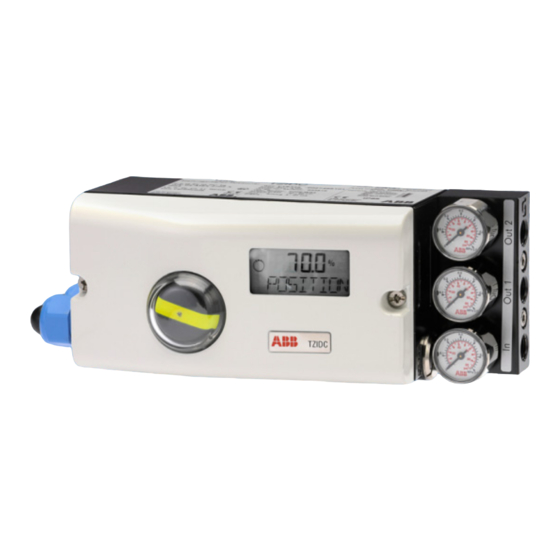
The TZIDC, TZIDC-110, TZIDC-120 is an electronically
TZIDC-120
configurable positioner with communication
capabilities designed for mounting on pneumatic
linear or rotary actuators.
Fully automatic determination of the control
parameters and adaptation to the positioner allow
for considerable time savings as well as optimum
control behavior.
Digital Positioner for the
positioning of pneumatically
controlled final control elements.
Additional Information
Additional documentation on TZIDC, TZIDC-110,
TZIDC-120 is available for download free of charge at
www.abb.com/positioners.
Alternatively simply scan this code:
Advertisement
Table of Contents

Related Manuals for ABB TZIDC


Summary of Contents for ABB TZIDC
- Page 1 The TZIDC, TZIDC-110, TZIDC-120 is an electronically Additional documentation on TZIDC, TZIDC-110, TZIDC-120 configurable positioner with communication TZIDC-120 is available for download free of charge at capabilities designed for mounting on pneumatic www.abb.com/positioners. linear or rotary actuators. Alternatively simply scan this code:...
-
Page 2: Table Of Contents
TZIDC, TZIDC-110, TZIDC-120 DIGITAL POSITIONER | CI/TZIDC/110/120-EN REV. E Table of contents Change from one to two columns Connection on the device ............. 38 Safety ................3 Conductor cross-section ..........39 General information and instructions ........3 ... -
Page 3: Safety
TZIDC, TZIDC-110, TZIDC-120 DIGITAL POSITIONER | CI/TZIDC/110/120-EN REV. E 1 Safety General information and instructions Warnings These instructions are an important part of the product and The warnings in these instructions are structured as follows: must be retained for future reference. -
Page 4: Intended Use
TZIDC, TZIDC-110, TZIDC-120 DIGITAL POSITIONER | CI/TZIDC/110/120-EN REV. E … 1 Safety Manufacturer’s address Intended use ABB Automation Products GmbH Positioning of pneumatically controlled actuators; designed for Measurement & Analytics mounting on linear and rotary actuators. Schillerstr. 72 The device is designed for use exclusively within the stated 32425 Minden values on the name plate and in the data sheet. -
Page 5: Use In Potentially Explosive Atmospheres
Commissioning, Installation Notes for operation The ABB positioner has to be mounted in a major system. • The positioner must be integrated in the local potential Depending on the degrees of IP-protection, an interval for equalization system. -
Page 6: Maintenance, Repair
TZIDC, TZIDC-110, TZIDC-120 DIGITAL POSITIONER | CI/TZIDC/110/120-EN REV. E … 2 Use in potentially explosive atmospheres Maintenance, repair Definition of terms according to IEC 60079-17: • Maintenance and exchange work may be conducted by Maintenance qualified specialists only, i.e., qualified personnel in Defines a combination of actions performed to maintain or accordance with TRBS 1203 or similar. -
Page 7: Preconditions For Safe Operation Of The Positioner
TZIDC, TZIDC-110, TZIDC-120 DIGITAL POSITIONER | CI/TZIDC/110/120-EN REV. E Preconditions for safe operation of the positioner Cable gland DANGER Limited temperature range of the M20 × 1.5 plastic cable gland Risk of explosion due to hot parts for explosion protection variants. -
Page 8: Tzidc - Ex Relevant Specification
TZIDC, TZIDC-110, TZIDC-120 DIGITAL POSITIONER | CI/TZIDC/110/120-EN REV. E … 2 Use in potentially explosive atmospheres TZIDC – Ex relevant specification Note Electrical Data The values indicated here are taken from the respective In intrinsically safe types of protection Ex ib IIC / Ex ia IIC or certificates. -
Page 9: Atex - 'Ex N' Type Of Protection
• When used with gases from group IIA and a temperature Type ’n’ type of protection class of T1 for power supply, the TZIDC positioner may only Device class II 3 G be used outdoors or inside sufficiently ventilated buildings. -
Page 10: Iecex - 'Ex I' And 'Ex N' Type Of Protection
T6, the maximum permissible ambient temperature range is −40 to 35 °C. Electrical Data Electric data for TZIDC with Ex ia IIC or Ex ib IIC marking. In ‘intrinsic safety Ex ib IIC / Ex ia IIC’ type of protection, only for connection to a certified intrinsically safe circuit. - Page 11 Note: It is considered very Electric data for TZIDC with Ex nA IIC T6 or T4 Gc marking unlikely that a potentially hazardous atmosphere would be present in zone 2 at the same time that installation or...
-
Page 12: Fm / Csa
TZIDC, TZIDC-110, TZIDC-120 DIGITAL POSITIONER | CI/TZIDC/110/120-EN REV. E … 2 Use in potentially explosive atmospheres … TZIDC – Ex relevant specification FM / CSA Note • The “x” in P/N denotes minor mechanical variations or CSA International optional features. - Page 13 TZIDC, TZIDC-110, TZIDC-120 DIGITAL POSITIONER | CI/TZIDC/110/120-EN REV. E Note CSA certification record • The ‘x’ in P/N denotes minor mechanical variations or optional features. Certificate • Local communication interface LCI shall not be used in Certificate 1649904 (LR 20312) hazardous location.
-
Page 14: Tzidc-110 - Ex Relevant Specification
TZIDC, TZIDC-110, TZIDC-120 DIGITAL POSITIONER | CI/TZIDC/110/120-EN REV. E … 2 Use in potentially explosive atmospheres TZIDC-110 – Ex relevant specification Note ATEX – ‘Ex n’ type of protection The values indicated here are taken from the respective Ex marking certificates. -
Page 15: Iecex - 'Ex I' And 'Ex N' Type Of Protection
−40 to 50 °C Electrical Data TZIDC-110 for ia / ib / ic with Ex i IIC T6 or T4 Gb marking With the intrinsically safe Ex i IIC type of protection, only for connection to a certified FISCO power supply unit, a barrier or a... -
Page 16: Fm / Csa
TZIDC, TZIDC-110, TZIDC-120 DIGITAL POSITIONER | CI/TZIDC/110/120-EN REV. E … 2 Use in potentially explosive atmospheres … TZIDC-110 – Ex relevant specification TZIDC-110 with Ex nA IIC T6 or T4 Gc marking FM / CSA CSA International Current circuit (terminal) - Page 17 TZIDC, TZIDC-110, TZIDC-120 DIGITAL POSITIONER | CI/TZIDC/110/120-EN REV. E CSA certification record FM approvals TZIDC-110 Positioner, Model V18346-a032b2cd0e Certificate IS/I,II,III/1/ABCDEFG/T6,T5,T4 Ta = 40 °C, 55 °C, 85 °C-901265 Entity, FISCO Certificate 1649904 (LR 20312) Class 2258 04 PROCESS CONTROL EQUIPMENT –...
- Page 18 TZIDC, TZIDC-110, TZIDC-120 DIGITAL POSITIONER | CI/TZIDC/110/120-EN REV. E … 2 Use in potentially explosive atmospheres … TZIDC-110 – Ex relevant specification Equipment Ratings: TZIDC-110 Intrinsically safe, Entity and FISCO, for Class I, II and III, Division 1, Applicable Groups A, B, C, D, E, F, G; non-Incendive for Class I,...
-
Page 19: Tzidc-120 - Ex Relevant Specification
TZIDC, TZIDC-110, TZIDC-120 DIGITAL POSITIONER | CI/TZIDC/110/120-EN REV. E TZIDC-120 – Ex relevant specification Note ATEX – ‘Ex n’ type of protection The values indicated here are taken from the respective Ex marking certificates. Always observe the specifications and supplements in the explosion protection certificates. -
Page 20: Iecex - 'Ex I' And 'Ex N' Type Of Protection
−40 to 50 °C Electrical Data TZIDC-120 for ia / ib / ic with Ex i IIC T6 or T4 Gb marking With the intrinsically safe Ex i IIC type of protection, only for connection to a certified FISCO power supply unit, a barrier or a... -
Page 21: Fm / Csa
TZIDC, TZIDC-110, TZIDC-120 DIGITAL POSITIONER | CI/TZIDC/110/120-EN REV. E TZIDC-120 with Ex nA IIC T6 or T4 Gc marking FM / CSA CSA International Current circuit (terminal) System bus, computer interfaces Signal circuit U = 9 to 32 V DC Certificate (+11 / −12) - Page 22 TZIDC, TZIDC-110, TZIDC-120 DIGITAL POSITIONER | CI/TZIDC/110/120-EN REV. E … 2 Use in potentially explosive atmospheres … TZIDC-120 – Ex relevant specification CSA certification record FM approvals TZIDC-120 Positioner, Model V18347-a042b2cd0e Certificate IS/I,II,III/1/ABCDEFG/T6,T5,T4 Ta = 40 °C, 55 °C, 85 °C-901265 Entity, FISCO...
-
Page 23: Product Identification
TZIDC, TZIDC-110, TZIDC-120 DIGITAL POSITIONER | CI/TZIDC/110/120-EN REV. E Change from two to one column 3 Product identification Name plate 1 Full type designation 6 Supply air pressure 2 Software revision 7 Input 3 Serial number 8 Output 4 NL number... -
Page 24: Transport And Storage
Transporting the device purposes: All devices delivered to ABB must be free from any hazardous Observe the following instructions: materials (acids, alkalis, solvents, etc.). •... -
Page 25: Installation
TZIDC, TZIDC-110, TZIDC-120 DIGITAL POSITIONER | CI/TZIDC/110/120-EN REV. E 5 Installation Safety instructions CAUTION Risk of injury due to incorrect parameter values! Incorrect parameter values can cause the valve to move unexpectedly. This can lead to process failures and result in injuries. -
Page 26: External Position Sensors
Remote Sensor on page 40. M10904 Note 1 TZIDC Control Unit 5 Compressed air supply To connect the TZIDC Remote Sensor, a cable with the following 2 Connection cable 6 Set point signal specifications needs to be used: 3 TZIDC Remote Sensor 7 Remote position sensor ²... -
Page 27: Mechanical Mounting
TZIDC, TZIDC-110, TZIDC-120 DIGITAL POSITIONER | CI/TZIDC/110/120-EN REV. E Mechanical mounting General Operating range of rotary actuators: The usable span is 90°, which must be entirely within the measuring range, but does not necessarily need to run symmetrically to the longitudinal axis. -
Page 28: Mounting On Linear Actuators
TZIDC, TZIDC-110, TZIDC-120 DIGITAL POSITIONER | CI/TZIDC/110/120-EN REV. E … 5 Installation … Mechanical mounting Mounting on linear actuators For mounting on a linear actuator in accordance with DIN / IEC 534 (lateral mounting as per NAMUR), the following attachment... - Page 29 TZIDC, TZIDC-110, TZIDC-120 DIGITAL POSITIONER | CI/TZIDC/110/120-EN REV. E 5. Secure the mount bracket with screws and washers Note using the relevant tap holes on the positioner housing. Adjust the height of the positioner on the cast iron yoke or ...
-
Page 30: Mounting On Rotary Actuator
TZIDC, TZIDC-110, TZIDC-120 DIGITAL POSITIONER | CI/TZIDC/110/120-EN REV. E … 5 Installation … Mechanical mounting Position of actuator bolt Mounting on rotary actuator The actuator bolt for moving the potentiometer lever can be For mounting on part-turn actuators in accordance with mounted permanently on the lever itself or on the valve stem. - Page 31 TZIDC, TZIDC-110, TZIDC-120 DIGITAL POSITIONER | CI/TZIDC/110/120-EN REV. E M10421-01 1 Attachment bracket M10424-01 Figure 15: Screwing the attachment bracket onto the positioner Figure 14: Mounting the adapter on the positioner 1. Determine the mounting position (parallel to actuator or at 90° angle) 2....
-
Page 32: Electrical Connections
TZIDC, TZIDC-110, TZIDC-120 DIGITAL POSITIONER | CI/TZIDC/110/120-EN REV. E 6 Electrical connections Safety instructions DANGER Risk of explosion for devices with local communication interface (LCI) A local communication interface (LCI) may not be operated in hazardous areas. • Never use the local communication interface (LCI) on the... -
Page 33: Tzidc / Tzidc Control Unit Terminal Assignment
It is not position sensor) possible to combine both variants. For the version TZIDC Control Unit with TZIDC Remote Sensor, the limit switches are located in the TZIDC Remote Sensor. Change from two to one column... -
Page 34: Tzidc Remote Sensor Terminal Assignment
Figure 18: TZIDC Remote Sensor Electrical Connection Change from one to two columns Connections for inputs and outputs Note The TZIDC Remote Sensor can be fitted either with proximity Terminal Function / comments switches or microswitches as limit switches. It is not possible to... -
Page 35: Tzidc-110, Tzidc-120 Terminal Assignment
Digital feedback Limit 1 with microswitch (optional) 51 / 52 / 53 Digital feedback Limit 2 with microswitch (optional) Note The TZIDC-1x0, TZIDC-210 or TZIDC-220 can be fitted either with proximity switches or microswitches as limit switches. It is not possible to combine both variants. -
Page 36: Electrical Data For Inputs And Outputs
TZIDC, TZIDC-110, TZIDC-120 DIGITAL POSITIONER | CI/TZIDC/110/120-EN REV. E … 6 Electrical connections Electrical data for inputs and outputs Note Digital input When using the device in potentially explosive atmospheres, Only for devices with HART® Communication. note the additional connection data in Use in potentially... -
Page 37: Option Modules
TZIDC, TZIDC-110, TZIDC-120 DIGITAL POSITIONER | CI/TZIDC/110/120-EN REV. E Option modules Assembly kits for digital feedback Module for analog feedback AO* Two proximity switches or microswitches for independent Only for devices with HART® Communication. signaling of the actuator position, switching points are Without any signal from the positioner (e.g. -
Page 38: Connection On The Device
TZIDC, TZIDC-110, TZIDC-120 DIGITAL POSITIONER | CI/TZIDC/110/120-EN REV. E hange from two to one column … 6 Electrical connections Connection on the device M 20 mm / NPT 1/2" M10901 1 Cable gland 4 Terminal attachment kit for digital feedback... -
Page 39: Conductor Cross-Section
TZIDC, TZIDC-110, TZIDC-120 DIGITAL POSITIONER | CI/TZIDC/110/120-EN REV. E Conductor cross-section Option modules Basic device Cross section Electrical connections Rigid / flexible wires 0.14 to 1.5 mm (AWG26 to AWG17) 4 to 20 mA input Screw terminals max. 2.5 mm... -
Page 40: Connection On Device - Tzidc Control Unit With Tzidc Remote Sensor
If necessary, the following options can be installed if required: • Optical position indicator • If the TZIDC Control Unit is fastened so that it is it non- • Mechanical feedback contacts designed as proximity conductive, the housing must be grounded (TZIDC Control switches or microswitches. -
Page 41: Connection On Device - Tzidc Control Unit For Remote Position Sensor
TZIDC / TZIDC Control Unit terminal assignment on page 33. • If the TZIDC Control Unit is fastened such that it is it non- conductive, the housing must be grounded (TZIDC Control Unit and remote position sensor housing with the same electric potential);... -
Page 42: Pneumatic Connections
TZIDC, TZIDC-110, TZIDC-120 DIGITAL POSITIONER | CI/TZIDC/110/120-EN REV. E 7 Pneumatic Connections Connection on the device Note The positioner must only be supplied with instrument air that is free of oil, water, and dust. The purity and oil content must meet the requirements of Class 3 in accordance with DIN/ISO 8573-1. -
Page 43: Air Supply
TZIDC, TZIDC-110, TZIDC-120 DIGITAL POSITIONER | CI/TZIDC/110/120-EN REV. E 8 Commissioning Air supply Note The electrical power supply and supply air pressure data Instrument air* indicated on the name plate must be complied with during commissioning. Purity Maximum particle size: 5 μm... -
Page 44: Operating Modes
TZIDC, TZIDC-110, TZIDC-120 DIGITAL POSITIONER | CI/TZIDC/110/120-EN REV. E … 8 Commissioning TZIDC-110 / TZIDC-120 … TZIDC Commissioning the positioner: Operating modes 1. Open the pneumatic power supply. Selection from the operating level 2. Connect fieldbus or power supply to the bus connections. -
Page 45: Setting The Bus Address
TZIDC, TZIDC-110, TZIDC-120 DIGITAL POSITIONER | CI/TZIDC/110/120-EN REV. E Setting the bus address Request information When the device is in bus operation, the information listed below 1. Switching to the configuration level: can be called up. • Press and hold down and simultaneously, Press the following control buttons to access this information: •... -
Page 46: Operating Modes
TZIDC, TZIDC-110, TZIDC-120 DIGITAL POSITIONER | CI/TZIDC/110/120-EN REV. E … 8 Commissioning Standard automatic adjustment … TZIDC-110 / TZIDC-120 Operating modes Note Standard Auto Adjust does not always result in optimum control Selection from the operating level: conditions. 1. Press and hold down MODE. -
Page 47: Sample Parameters
TZIDC, TZIDC-110, TZIDC-120 DIGITAL POSITIONER | CI/TZIDC/110/120-EN REV. E Sample parameters 4. Changing parameter settings: ‘Change the zero position of the LCD display from clockwise • Quickly press and release to select CTCLOCKW. (CLOCKW) to counter-clockwise limit stop (CTCLOCKW)’... -
Page 48: Setting The Mechanical Limit Switch With Proximity Switches
TZIDC, TZIDC-110, TZIDC-120 DIGITAL POSITIONER | CI/TZIDC/110/120-EN REV. E … 8 Commissioning … Sample parameters Setting the mechanical limit switch with proximity Setting the mechanical limit switch with 24 V switches microswitches 1. Loosen the screws for the housing cover and remove it. -
Page 49: Operation
TZIDC, TZIDC-110, TZIDC-120 DIGITAL POSITIONER | CI/TZIDC/110/120-EN REV. E 9 Operation Safety instructions Value display with unit CAUTION This 7-segment display with four digits indicates parameter Risk of injury due to incorrect parameter values! values or parameter reference numbers. For values, the physical Incorrect parameter values can cause the valve to move unit (°C, %, mA) is also displayed. -
Page 50: Menu Levels
TZIDC, TZIDC-110, TZIDC-120 DIGITAL POSITIONER | CI/TZIDC/110/120-EN REV. E … 9 Operation 10 Maintenance … Parameterization of the device The positioner does not require any maintenance if it is used as intended under normal operating conditions. Operating button functions Note... -
Page 51: Appendix
TZIDC, TZIDC-110, TZIDC-120 DIGITAL POSITIONER | CI/TZIDC/110/120-EN REV. E 13 Appendix Return form Statement on the contamination of devices and components Repair and/or maintenance work will only be performed on devices and components if a statement form has been completed and submitted. -
Page 52: Fm Installation Drawing No. 901064
TZIDC, TZIDC-110, TZIDC-120 DIGITAL POSITIONER | CI/TZIDC/110/120-EN REV. E … 13 Appendix FM installation drawing No. 901064... - Page 53 TZIDC, TZIDC-110, TZIDC-120 DIGITAL POSITIONER | CI/TZIDC/110/120-EN REV. E...
- Page 54 TZIDC, TZIDC-110, TZIDC-120 DIGITAL POSITIONER | CI/TZIDC/110/120-EN REV. E … 13 Appendix … FM installation drawing No. 901064...
- Page 55 TZIDC, TZIDC-110, TZIDC-120 DIGITAL POSITIONER | CI/TZIDC/110/120-EN REV. E...
-
Page 56: Fm Installation Drawing No. 901265
TZIDC, TZIDC-110, TZIDC-120 DIGITAL POSITIONER | CI/TZIDC/110/120-EN REV. E … 13 Appendix FM installation drawing No. 901265... - Page 57 TZIDC, TZIDC-110, TZIDC-120 DIGITAL POSITIONER | CI/TZIDC/110/120-EN REV. E...
- Page 58 TZIDC, TZIDC-110, TZIDC-120 DIGITAL POSITIONER | CI/TZIDC/110/120-EN REV. E … 13 Appendix … FM installation drawing No. 901265...
- Page 59 TZIDC, TZIDC-110, TZIDC-120 DIGITAL POSITIONER | CI/TZIDC/110/120-EN REV. E Change from one to two columns Trademarks HART is a registered trademark of FieldComm Group, Austin, Texas, USA FOUNDATION Fieldbus is a registered trademark of FieldComm Group, Austin, Texas, USA. PROFIBUS and PROFIBUS PA are registered trademarks of PROFIBUS &...
- Page 60 We reserve the right to make technical changes or modify the contents of this document without prior notice. With regard to purchase orders, the agreed particulars shall prevail. ABB does not accept any responsibility whatsoever for potential errors or possible lack of information in this document.