Table of Contents
Advertisement
Quick Links
Download this manual
See also:
Instruction Manual
GE Digital Energy
Multilin
339 revision: 1.40
Manual P/N: 1601-9103-A3
GE publication code: GEK-113562B
Copyright © 2010 GE Multilin
GE Multilin
215 Anderson Avenue, Markham, Ontario
Canada L6E 1B3
Tel: (905) 294-6222 Fax: (905) 201-2098
Internet:
http://www.GEmultilin.com
*1601-9103-A3*
Motor Protection System
Instruction manual
Motor protection and control
registered to ISO9001:2000
339
GE Multilin's Quality
Management System is
QMI # 005094
Advertisement
Table of Contents

Related Manuals for GE 339


Summary of Contents for GE 339
- Page 1 Motor Protection System Motor protection and control Instruction manual 339 revision: 1.40 Manual P/N: 1601-9103-A3 GE publication code: GEK-113562B Copyright © 2010 GE Multilin GE Multilin 215 Anderson Avenue, Markham, Ontario Canada L6E 1B3 Tel: (905) 294-6222 Fax: (905) 201-2098 Internet: http://www.GEmultilin.com...
- Page 2 The contents of this manual are the property of GE Multilin Inc. This documentation is furnished on license and may not be reproduced in whole or in part without the permission of GE Multilin. The content of this manual is for informational use only and is subject to change without notice.
-
Page 3: Table Of Contents
Table of Contents 1.INTRODUCTION Overview ..........................1 - 1 Cautions and warnings ....................1 - 2 Description of the 339 Motor Protection System..........1 - 3 339 order codes........................1 - 6 Specifications........................1 - 7 Password security........................1 - 7 Protection.............................1 - 7 Metering............................1 - 10 Data capture ..........................1 - 11... - Page 4 Hardware and software requirements.................3 - 11 Installing the EnerVista SR3 Setup software ..............3 - 11 Connecting EnerVista SR3 Setup to the relay ............3 - 14 Configuring serial communications................3 - 14 Using the Quick Connect feature ..................3 - 15 Configuring Ethernet communications ................3 - 16 Connecting to the relay......................3 - 17 Working with setpoints and setpoint files ..............3 - 18 Engaging a device ........................3 - 18...
- Page 5 Event records ..........................4 - 13 Transient records ........................4 - 30 Learned data ..........................4 - 30 Learned data recorder......................4 - 32 Clear learned data ........................4 - 32 Clear transient record ......................4 - 32 Clear event record ........................4 - 32 A4 Target messages ......................4 - 33 5.QUICK SETUP - Quick Setup settings......................5 - 3 FRONT CONTROL...
- Page 6 Neutral instantaneous overcurrent................. 6 - 88 Phase undervoltage........................ 6 - 90 Phase overvoltage........................6 - 93 Underfrequency........................6 - 96 Overfrequency........................... 6 - 99 Underpower..........................6 - 102 Negative sequence overvoltage..................6 - 105 Phase reversal ........................... 6 - 107 VT fuse fail ...........................
-
Page 7: Introduction Overview
Introduction Overview The 339 Motor Protection System is a microprocessor based relay providing suitable protection of medium voltage motors. The small footprint and the withdrawable option make the relay ideal for panel mounting on either new or retrofit installations. The combination of proven hardware, a variety of protection and control features, and communications, makes the relay ideal for total motor protection and control. -
Page 8: Cautions And Warnings
The caution icon indicates that possible damage to equipment or data may occur if instructions are not properly followed. The danger icon provides users with a warning about the possibility of serious or fatal injury to themselves or others. 1–2 339 MOTOR PROTECTION SYSTEM – INSTRUCTION MANUAL... -
Page 9: Description Of The 339 Motor Protection System
CHAPTER 1: INTRODUCTION DESCRIPTION OF THE 339 MOTOR PROTECTION SYSTEM Description of the 339 Motor Protection System Relay functions are controlled by two processors: a Freescale MPC5554 32-bit microprocessor measures all analog signals and digital inputs and controls all output relays;... - Page 10 DESCRIPTION OF THE 339 MOTOR PROTECTION SYSTEM CHAPTER 1: INTRODUCTION Figure 2: Line Diagram 27P 59P 47 59_2 81O 81U 59_2 50P 50BF Phase CT 3 Ambient air TRIP Ground CT 1 Stator RTDs CLOSE Bearing RTDs START START INHIBIT...
- Page 11 CHAPTER 1: INTRODUCTION DESCRIPTION OF THE 339 MOTOR PROTECTION SYSTEM Figure 3: Main Menu structure ACTUAL VALUES ACTUAL VALUES QUICK SETUP A1 STATUS THERMAL PROTECTION SETPOINTS A2 METERING START PROTECTION MAINTENANCE A3 RECORDS ▼ ▼ LOCKED ROTOR CURR A4 TARGET MESSAGES...
-
Page 12: 339 Order Codes
339 ORDER CODES CHAPTER 1: INTRODUCTION 339 order codes The information to specify a 339 relay is provided in the following order code table. Figure 4: Order Codes 1–6 339 MOTOR PROTECTION SYSTEM – INSTRUCTION MANUAL... -
Page 13: Specifications
Time Delay: ............1.00 to 60.00 s in steps of 0.01 s Block from Start:..........0 to 600 s in steps of 1 s Pickup Accuracy:..........as per phase current inputs Timing Accuracy: ..........±0.5 s or ± 0.5% of total time Elements: ..............Trip and Alarm 339 MOTOR PROTECTION SYSTEM – INSTRUCTION MANUAL 1–7... - Page 14 Dropout Level:............96 to 99% of Pickup Trip Time Delay:........... 0.10 to 30.00 s in steps of 0.01 s Pickup Accuracy:..........as per phase current inputs Timing Accuracy:..........±0.5 s or ±0.5% of total time 1–8 339 MOTOR PROTECTION SYSTEM – INSTRUCTION MANUAL...
- Page 15 Operate Time:............Time delay ±30 ms @ 60 Hz (V < 0.85 x PKP) Time delay ±40 ms @ 50 Hz (V < 0.85 x PKP) Timing Accuracy: ..........±0.5 s or ±0.3% of total time Level Accuracy:............Per voltage input 339 MOTOR PROTECTION SYSTEM – INSTRUCTION MANUAL 1–9...
-
Page 16: Metering
3-Phase Negative Varhour (Mvarh) ±1% of full scale ±0.001 Mvarh 50000.0 Mvarh ±0.05 Power Factor 0.01 -0.99 to 1.00 ±0.05 Hz Frequency 0.01 Hz 40.00 to 70.00 Hz Full scale for CT Input is 3 x CT NOTE: NOTE 1–10 339 MOTOR PROTECTION SYSTEM – INSTRUCTION MANUAL... -
Page 17: Data Capture
RTC Accuracy: ± 1 min / month at 25°C IRIG-B:...............Auto-detect (DC shift or Amplitude Modulated) Amplitude modulated: 1 to 10 V pk-pk DC shift: 1 to 10 V DC Input impedance: 40 kOhm ± 10% at 25°C 339 MOTOR PROTECTION SYSTEM – INSTRUCTION MANUAL 1–11... -
Page 18: Control
Low Temperature Pickup: ....... -40°C to 20°C in steps of 1°C Time Delay:............1 to 60 min in steps of 1 mins Temperature Dropout:........Configurable 90 to 98% of pickup Temperature Accuracy: ........±10°C Timing Accuracy:..........±1 second 1–12 339 MOTOR PROTECTION SYSTEM – INSTRUCTION MANUAL... -
Page 19: Inputs
RTD Type: ..............100 Ohm platinum (DIN.43760) RTD Sensing Current:.........5 mA Isolation:..............2 kV from base unit Distance: ..............250 m maximum Range: ..............-50 to +250 Accuracy: ..............±2 Lead Resistance: ..........25 Ohm max per lead 339 MOTOR PROTECTION SYSTEM – INSTRUCTION MANUAL 1–13... -
Page 20: Outputs
Range:..............20 to 60 VDC ALL RANGES Voltage withstand:..........2 × highest nominal voltage for 10 ms Power consumption: ......... 15 W nominal, 20 W maximum 20 VA nominal, 28 VA maximum 1–14 339 MOTOR PROTECTION SYSTEM – INSTRUCTION MANUAL... -
Page 21: Communications
2.5KV CM, 1KV DM Electrostatic Discharge EN61000-4-2/IEC60255-22-2 Level 4 Radiated RF immunity EN61000-4-3/IEC60255-22-3 Level 3 Fast Transient Disturbance EN61000-4-4/IEC60255-22-4 Level 4 Surge Immunity EN61000-4-5/IEC60255-22-5 Level 3 & 4 Conducted RF Immunity EN61000-4-6/IEC60255-22-6 Level 3 339 MOTOR PROTECTION SYSTEM – INSTRUCTION MANUAL 1–15... -
Page 22: Physical
Humidity: Operating up to 95% (non condensing) @ 55 C (As per IEC60068-2-30 Variant 2, 6 days) Altitude: 2000 m (max) Pollution Degree: Overvoltage Category: Ingress Protection: IP40 Front , IP10 Back 1–16 339 MOTOR PROTECTION SYSTEM – INSTRUCTION MANUAL... -
Page 23: Installation Mechanical Installation
Digital Energy Multilin 339 Motor Protection System Chapter 2: Installation Installation Mechanical installation This section describes the mechanical installation of the system, including dimensions for mounting and information on module withdrawal and insertion. 339 MOTOR PROTECTION SYSTEM – INSTRUCTION MANUAL 2–1... -
Page 24: Dimensions
Figure 1: 339 dimensions Product identification The product identification label is located on the side panel of the 339. This label indicates the product model, serial number, and date of manufacture. Figure 2: Product Identification label 2–2... -
Page 25: Mounting
NOTE: IT IS THE RESPONSIBILITY OF THE USER TO ENSURE THAT THE EQUIPMENT IS INSTALLED, OPERATED, AND USED FOR ITS INTENDED FUNCTION, IN THE MANNER SPECIFIED BY THE MANUFACTURER. IF THIS IS NOT THE CASE, THEN THE SAFETY PROTECTION PROVIDED BY THE EQUIPMENT MAY BE IMPAIRED. 339 MOTOR PROTECTION SYSTEM – INSTRUCTION MANUAL 2–3... - Page 26 (104.1 mm 0.25 mm) ± Φ 0.200” (5.1 mm) 6.900” 0.010” ± (175.3 mm 0.25 mm) ± 6.000” 0.010” ± (152.4 mm 0.25 mm) ± 4.000” 0.010” ± (101.6 mm 0.25 mm) ± 2–4 339 MOTOR PROTECTION SYSTEM – INSTRUCTION MANUAL...
- Page 27 Figure 7: RMIO - Base Unit screw mounting MEETS VIBRATION REQUIREMENT OF IEC 60255 SEC 21.1, 21.2, & 21.3 2.250” (57,15 mm) #6 -32 THREADED HOLE QTY: 2 4.100” (104,14 mm) 853727A1.CDR 339 MOTOR PROTECTION SYSTEM – INSTRUCTION MANUAL 2–5...
- Page 28 OUTLI E #6-32 THREADED HOLE 1.500” QTY: 2 [38.10 mm] 853755A1.cdr #6-32X1/2 FT FLAT HEAD PHIL ZI C QTY: 2; (SUPPLIED); GE PART # 1406-0117 TIGHTE I G TORQUE: 10 lb. in. 2–6 339 MOTOR PROTECTION SYSTEM – INSTRUCTION MANUAL...
-
Page 29: Unit Withdrawal And Insertion
NOTE: IT IS THE RESPONSIBILITY OF THE USER TO ENSURE THAT THE EQUIPMENT IS INSTALLED, OPERATED, AND USED FOR ITS INTENDED FUNCTION, IN THE MANNER SPECIFIED BY THE MANUFACTURER. IF THIS IS NOT THE CASE, THEN THE SAFETY PROTECTION PROVIDED BY THE EQUIPMENT MAY BE IMPAIRED. 339 MOTOR PROTECTION SYSTEM – INSTRUCTION MANUAL 2–7... -
Page 30: Electrical Installation
3 START I HIBIT OPE DELTA VT CO ECTIO START STOP 4 TRIP CO TACTOR COIL 5 AUXILIARY 6 AUXILIARY 7 CRITICAL 896729.CDR SELF TEST ANNUNCIATOR FAILURE E9 D9 E10D10 E11 D11 2–8 339 MOTOR PROTECTION SYSTEM – INSTRUCTION MANUAL... -
Page 31: 339 Terminal Identification
AUX 6 COM PHASE B VT ■ AUX 6 N/O PHASE C VT INPUT COM CRIT FAIL N/C PHASE C VT ■ CRIT FAIL COM CBCT CHASSIS GND CRIT FAIL N/O CBCT 339 MOTOR PROTECTION SYSTEM – INSTRUCTION MANUAL 2–9... - Page 32 AUX 6 COM PHASE B VT ■ AUX 6 N/O PHASE C VT INPUT COM CRIT FAIL N/C PHASE C VT ■ CRIT FAIL COM CBCT CHASSIS GND CRIT FAIL N/O CBCT 2–10 339 MOTOR PROTECTION SYSTEM – INSTRUCTION MANUAL...
-
Page 33: Rmio Module Installation
Figure 13: RMIO unit showing 2 IO_G modules Figure 14: RMIO terminal identification with 4 IO_G modules IO_G IO_G IO_G IO_G Common 896750.cdr 339 MOTOR PROTECTION SYSTEM – INSTRUCTION MANUAL 2–11... - Page 34 SCADA/PLC/COMPUTER ONLY OR THE MM300 ONLY (*) TERMINATING IMPEDANCE AT EACH END (typically 120 ohms and 1 nF) F5, F7, and F8 refer to terminals shown on the above 339 Terminal Identification diagrams. NOTE: NOTE Figure 16: RTD wiring 339 Motor Protection System...
-
Page 35: Phase Sequence And Transformer Polarity
CAUTION Ground and CBCT inputs The 339 has two isolating transformers with separate terminals for the 1A/5A secondary and the CBCT (50:0.025). Only one ground terminal type can be used at a time. There are no internal ground connections on the ground current inputs. -
Page 36: Zero Sequence Cbct Installation
Ground connection to neutral Stress cone must be on the source side Source Source shields Ground outside CT SHIELDED TWISTED PAIR SHIELDED TWISTED PAIR To ground; LOAD must be on load side LOAD 896791.CDR 2–14 339 MOTOR PROTECTION SYSTEM – INSTRUCTION MANUAL... -
Page 37: Voltage Inputs
CAUTION Belden catalog number 8660 is suitable. Isolate power prior to servicing. CAUTION: CAUTION An external switch, circuit breaker, or other protective device must be connected close to NOTE: the equipment. NOTE 339 MOTOR PROTECTION SYSTEM – INSTRUCTION MANUAL 2–15... -
Page 38: Contact Inputs
The relay is equipped with seven electromechanical output relays: 2 Form A (Relay 1, Relay 2), and 5 Form C (Relays 3 to 7). When SWITCHING DEVICE is selected as BREAKER: Output Relays: 2–16 339 MOTOR PROTECTION SYSTEM – INSTRUCTION MANUAL... - Page 39 Example: The figures below show the two different connections of the breaker trip (close) coil to the relay’s trip output #1 terminals (close output #2 terminals) for both no voltage monitoring and voltage monitoring of the trip (close) circuit integrity. 339 MOTOR PROTECTION SYSTEM – INSTRUCTION MANUAL 2–17...
- Page 40 When SWITCHING DEVICE is selected as CONTACTOR Output Relays: • Not Used: – Output Relay 1 – Output Relay 2 • For special purpose: – Output Relay 3 (self-reset): Start Inhibit – Output Relay 4 (fail-safe, non-fail-safe): Trip 2–18 339 MOTOR PROTECTION SYSTEM – INSTRUCTION MANUAL...
-
Page 41: Serial Communications
The source computer/PLC/SCADA system should have similar transient protection devices installed, either internally or externally. Ground the shield at one point only, as shown in the figure above, to avoid ground loops. 339 MOTOR PROTECTION SYSTEM – INSTRUCTION MANUAL 2–19... -
Page 42: Irig-B
GPS SATELLITE SYSTEM GPS CONNECTION OPTIONAL GE MULTILIN IRIG-B 339 RELAY RG58/59 COAXIAL CABLE TIME CODE GENERATOR IRIG-B(+) RECEIVER (DC SHIFT OR – AMPLITUDE MODULATED IRIG-B(-) SIGNAL CAN BE USED) 896741.CDR TO OTHER DEVICES 2–20 339 MOTOR PROTECTION SYSTEM – INSTRUCTION MANUAL... - Page 43 • Interfacing via the software. This section provides an overview of the interfacing methods available with the 339 using the relay control panel and software. For additional details on interface parameters (for example, settings, actual values, etc.), refer to the individual chapters.
-
Page 44: Description
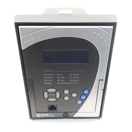
FRONT CONTROL PANEL INTERFACE CHAPTER 3: INTERFACES Front control panel interface Figure 1: 339 Motor Protection System front panel GE Multilin 339 Motor Protection System TRIP STOPPED I SERVICE TROUBLE ALARM STARTI G LOCKOUT PICKUP START MAI TE A CE... -
Page 45: Display
A3 RECORDS CONTACT INPUTS ▽ Back ◁ ▷ ▼ 2 clicks A1 STATUS MOTOR STATUS CLOCK █ CONTACT INPUTS Back ◁ ▷ ▼ Click to end A1 STATUS █ RTD TEMP SUMMARY 339 MOTOR PROTECTION SYSTEM – INSTRUCTION MANUAL 3–3... -
Page 46: Led Status Indicators
"OFF" when the values go below the threshold. • MAINTENANCE: Amber – Turns "ON" when either the Trip or the Close Coil Monitor element is activated, or the Trip Counter has exceeded the programmed value. 3–4 339 MOTOR PROTECTION SYSTEM – INSTRUCTION MANUAL... - Page 47 LED color is programmable. Turns "ON" when the motor status is "Running". • HOT RTD: Amber – Turns "ON" when either a RTD Alarm or Trip has been activated. – Self-resetting when the fault is no longer present. 339 MOTOR PROTECTION SYSTEM – INSTRUCTION MANUAL 3–5...
-
Page 48: Relay Messages
The following shows the format of a typical Target Message: Figure 5: Typical target message A4 TARGET MESSAGES Cause <function> State: Operate Phase: 3–6 339 MOTOR PROTECTION SYSTEM – INSTRUCTION MANUAL... -
Page 49: Self-Test Errors
• Display the cause of major self-test failure. • Record the major self-test failure in the Event Recorder. Figure 7: Typical Self-test warning A4 TARGET MESSAGES UNIT FAILURE: Contact Factory: Error code:1 339 MOTOR PROTECTION SYSTEM – INSTRUCTION MANUAL 3–7... - Page 50 STATUS setting is RELAY SETUP > to "Not Ready". altered. INSTALLATION > RELAY STATUS setting to "Ready". 1.Failure is logged after the detection of 5 consecutive failures - that is, after 25 seconds. 3–8 339 MOTOR PROTECTION SYSTEM – INSTRUCTION MANUAL...
-
Page 51: Flash Messages
This flash message is displayed in response to executing a command: ON, OFF, YES, NO, etc. INVALID PASSWORD This flash message appears upon an attempt to enter an incorrect password, as part of password security. 339 MOTOR PROTECTION SYSTEM – INSTRUCTION MANUAL 3–9... -
Page 52: Software Setup
Although settings can be entered manually using the control panel keys, a PC can be used to download setpoints through the communications port. The software is available from GE Multilin to make this as convenient as possible. With the 339 relay running, it is possible •... -
Page 53: Hardware And Software Requirements
The software can run without a 339 connected to the computer. In this case, settings may be saved to a file for future use. If a 339 is connected to a PC and communications are enabled, the 339 can be programmed from the setting screens. In addition, measured values, status and trip messages can be displayed with the actual value screens. - Page 54 Windows start menu. The device will be added to the list of installed IEDs in the EnerVista Launchpad window, as shown below. 3–12 339 MOTOR PROTECTION SYSTEM – INSTRUCTION MANUAL...
- Page 55 10. Plug the USB cable into the USB port on the Relay then into the USB port on your computer. 11. Launch EnerVista SR3 Setup from LaunchPad. 12. In EnerVista > Device Setup: 339 MOTOR PROTECTION SYSTEM – INSTRUCTION MANUAL 3–13...
-
Page 56: Connecting Enervista Sr3 Setup To The Relay
F485 manual for additional details. To configure the relay for Ethernet communications, see Configuring Ethernet Communications below. Install and start the latest version of the software (available from the GE Multilin web site). See the previous section for the installation procedure. -
Page 57: Using The Quick Connect Feature
The Quick Connect button can be used to establish a fast connection through the front panel USB port of a relay, or through the Ethernet port. The following window will appear Connect feature when the QuickConnect button is pressed: 339 MOTOR PROTECTION SYSTEM – INSTRUCTION MANUAL 3–15... -
Page 58: Configuring Ethernet Communications
Ethernet communications. Proceed to Connecting to the Relay below, to begin communications. Configuring Ethernet Before starting, verify that the Ethernet cable is properly connected to the RJ-45 Ethernet communications port. The 339 relay supports a maximum of 3 TCP/IP sessions. NOTE: NOTE 3–16 339 MOTOR PROTECTION SYSTEM – INSTRUCTION MANUAL... -
Page 59: Connecting To The Relay
CHAPTER 3: INTERFACES SOFTWARE SETUP Install and start the latest version of the Setup software (available from the GE EnerVista CD). See the previous section for the installation procedure. Click on the Device Setup button to open the Device Setup window and click the Add Site button to define a new site. -
Page 60: Working With Setpoints And Setpoint Files
Sites may contain any number of relays selected from the product series. Entering setpoints The System Setup page will be used as an example to illustrate the entering of setpoints. In this example, we will be changing the voltage sensing setpoints. 3–18 339 MOTOR PROTECTION SYSTEM – INSTRUCTION MANUAL... - Page 61 In the Setpoint > System Setup > Voltage Sensing dialog box, click on Save to save the values into the . Click YES to accept any changes and exit the window. Click Restore to retain previous values. Click Default to restore Default values. 339 MOTOR PROTECTION SYSTEM – INSTRUCTION MANUAL 3–19...
-
Page 62: File Support
Adding setpoints files The software provides the capability to review and manage a large group of setpoint files. to the environment Use the following procedure to add an existing file to the list. 3–20 339 MOTOR PROTECTION SYSTEM – INSTRUCTION MANUAL... -
Page 63: Creating A New Setpoint File
It is important to define the correct firmware version to ensure that setpoints not available in a particular version are not downloaded into the relay. 339 MOTOR PROTECTION SYSTEM – INSTRUCTION MANUAL 3–21... -
Page 64: Upgrading Setpoint Files To A New Revision
File Version of the setpoint file. If this version is different from the Firmware Revision noted in step 2, select a New File Version that matches the Firmware Revision from the pull-down menu. 3–22 339 MOTOR PROTECTION SYSTEM – INSTRUCTION MANUAL... -
Page 65: Printing Setpoints And Actual Values
Include All Features (for a complete list) or Include Only Enabled Features (for a list of only those features which are currently used) in the filtering section and click OK. 339 MOTOR PROTECTION SYSTEM – INSTRUCTION MANUAL 3–23... -
Page 66: Printing Actual Values From A Connected Device
OK. Actual values lists can be printed in the same manner by right clicking on the desired device (in the device list) and selecting the Print Device Information option 3–24 339 MOTOR PROTECTION SYSTEM – INSTRUCTION MANUAL... -
Page 67: Loading Setpoints From A File
NOTE: relay. NOTE Before upgrading firmware, it is very important to save the current 339 settings to a file on NOTE: your PC. After the firmware has been upgraded, it will be necessary to load this file back into the . Refer to Downloading and Saving Setpoints Files for details on saving relay NOTE setpoints to a file. - Page 68 (i.e. default values, min/max values, data type, and item size) may change slightly from version to version of the firmware. Addresses are rearranged when new features are added or existing features are enhanced or modified. 3–26 339 MOTOR PROTECTION SYSTEM – INSTRUCTION MANUAL...
-
Page 69: Advanced Enervista Sr3 Setup Features
To view a previously saved COMTRADE file, click the Open button and select the corresponding COMTRADE file. To view the datalog, click the Launch Viewer button. A detailed Datalog window will appear as shown below. 339 MOTOR PROTECTION SYSTEM – INSTRUCTION MANUAL 3–27... -
Page 70: Motor Start Data Logger
Release (when Continuous mode is disabled). Motor start data When a motor start status is detected by the 339 relay, a start data logger is triggered and logger begins to sample and record the following parameters at a rate of 1 sample every 200ms: •... - Page 71 To view the datalog, click the Launch Viewer button. A detailed Datalog window will appear as shown below. For an explanation of the components of this screen, please refer to the Data Logger section above. 339 MOTOR PROTECTION SYSTEM – INSTRUCTION MANUAL 3–29...
-
Page 72: Transient Recorder (Waveform Capture)
Click on Trigger Waveform to trigger a waveform capture. Waveform file numbering starts with the number zero in the , so that the maximum trigger number will always be one less than the total number of triggers available. 3–30 339 MOTOR PROTECTION SYSTEM – INSTRUCTION MANUAL... - Page 73 339 MOTOR PROTECTION SYSTEM – INSTRUCTION MANUAL 3–31...
- Page 74 The Waveform Capture window will reappear based on the selected graph attributes. To view a vector graph of the quantities contained in the waveform capture, press the Vector Display button to display the following window: 3–32 339 MOTOR PROTECTION SYSTEM – INSTRUCTION MANUAL...
-
Page 75: Protection Summary
• view the enable/disable status of Control Elements • navigate to the respected Protection Element screen on a button click. The Protection Summary screen is as follows: 339 MOTOR PROTECTION SYSTEM – INSTRUCTION MANUAL 3–33... -
Page 76: Password Security
EnerVista setup software. This section describes how to perform the initial setup. For more details on the password security feature, refer to Chapter 6 - Password Security. 3–34 339 MOTOR PROTECTION SYSTEM – INSTRUCTION MANUAL... - Page 77 CHAPTER 3: INTERFACES SOFTWARE SETUP 339 devices shipped from the factory are initially set with security disabled. If the password security feature is to be used, the user must first change the Master Reset Password from the initial Null setting, this can only be done over communications, not from the front panel keypad.
- Page 78 The access level turns off after a period of 5 minutes of inactivity, if control power is cycled, or if the user enters an incorrect password. 3–36 339 MOTOR PROTECTION SYSTEM – INSTRUCTION MANUAL...
-
Page 79: Actual Values
All measured values, the status of digital inputs and outputs, and fault analysis information are accessed in Actual Values mode. Actual value messages are organized into logical groups for easy reference as shown below. 339 MOTOR PROTECTION SYSTEM – INSTRUCTION MANUAL 4–1... - Page 80 LEARNED DATA REC A2 POWER RTD #12 MAX TEMP CLEAR EVENT REC 3PH REAL POWER CLEAR TRANST REC ▼ CLEAR LEARNED DATA 3PH REACTIVE POWER 3PH APPARENT PWR POWER FACTOR A4 TARGET MESSAGES 896760A1.cdr 4–2 339 MOTOR PROTECTION SYSTEM – INSTRUCTION MANUAL...
-
Page 81: A1 Status
LOGIC ELEMENT A1 VIRTUAL INPUTS VIRTUAL INPUT ▼ VIRTUAL INPUT VIRTUAL INPUT A1 REMOTE INPUTS REMOTE INPUT ▼ REMOTE INPUT REMOTE INPUT REMOTE OUTPUTS REMOTE OUTPUTS ▼ REMOTE OUTPUTS 896748A1.cdr REMOTE OUTPUTS 339 MOTOR PROTECTION SYSTEM – INSTRUCTION MANUAL 4–3... -
Page 82: Motor Status
STARTS/HR INHIBIT Time in seconds left until the Starts per Hour feature’s inhibit expires. Has a value of zero if this feature is set to OFF, or if the time has expired. 4–4 339 MOTOR PROTECTION SYSTEM – INSTRUCTION MANUAL... - Page 83 A thermal overload lockout will occur after a thermal overload trip so that the user cannot start the motor until the TCU drops to 15%. Following a thermal overload trip, this value indicates how long it will take for the 339 relay TCU to decrease from the current value to 15%.
-
Page 84: Clock
Output Relay #2 (CLOSE) Range: Off, On The “ON” state of Output Relay #2 (Breaker CLOSE) shows that a CLOSE command has been sent to the breaker. Output Relay #3 (START INHIBIT) Range: Off, On 4–6 339 MOTOR PROTECTION SYSTEM – INSTRUCTION MANUAL... -
Page 85: Output Relays - Contactor
VIRTUAL INPUTS 1 to 32 Range: Off, On Remote inputs The state of all remote inputs is displayed here. PATH: ACTUAL VALUES > A1 STATUS > REMOTE INPUTS REMOTE INPUTS 1 to 32 Range: Off, On 339 MOTOR PROTECTION SYSTEM – INSTRUCTION MANUAL 4–7... -
Page 86: Remote Outputs
Output relay #7 is the Critical Failure relay, used to indicate the correct functioning of the NOTE: 339 relay. This output relay shows the status "ON" when the relay is powered up and set to "Ready" under SETPOINTS > S1 RELAY SETUP > S1 INSTALLATION > RELAY STATUS NOTE no self-test alarms are active. -
Page 87: Goose Status
Range: OFF, ON Default: OFF RTD temp summary PATH: ACTUAL VALUES > A1 STATUS > RTD TEMP SUMMARY RTD TEMP SUMMARY This display shows a summary of the states of all RTDs. 339 MOTOR PROTECTION SYSTEM – INSTRUCTION MANUAL 4–9... -
Page 88: A2 Metering
Range: 0.00 to 15.00 A, 0 to 359 SENS GND CURRENT is shown when the GROUND CT TYPE is set to "50:0.025". NEG SEQ CURRENT 0.0 A 0 Range: 0.0 to 30000 A, 0 to 359 4–10 339 MOTOR PROTECTION SYSTEM – INSTRUCTION MANUAL... -
Page 89: Voltage
Range: 40 to 70 Hz Power 3 ph REAL POWER 0.0 kV Range: -100000.0 to 100000.0 kW 3 ph REACTIVE POWER 0.0 kVAR Range: -100000.0 to 100000.0 kVAR 3 ph APPARENT POWER 0.0 kVA 339 MOTOR PROTECTION SYSTEM – INSTRUCTION MANUAL 4–11... -
Page 90: Energy
Range: -50 C to 250 RTD12 TEMPERATURE Range: -50 C to 250 Clear energy CLEAR ENERGY Range: No, Yes When set to "YES," pressing the ENTER key will clear all energy data. 4–12 339 MOTOR PROTECTION SYSTEM – INSTRUCTION MANUAL... -
Page 91: A3 Records
Refer to Advanced EnerVista SR3 Setup features in Chapter 3. Event records The 339 has an event recorder which runs continuously. All event records are stored in memory such that information is maintained for up to 3 days even after losing relay control power. - Page 92 Logic Element Events L. ELEMENT These are events that occur when a logic element changes its state Self-Test Warning Events SELF-TEST WARNING These are events that occur when a self- test warning is detected. 4–14 339 MOTOR PROTECTION SYSTEM – INSTRUCTION MANUAL...
- Page 93 CHAPTER 4: ACTUAL VALUES A3 RECORDS The following table, from the 339 Communications Guide, shows the list of Event Causes. Code Type Definition FC134 unsigned 16 bits Cause of Event No Evnt/Trp ToDate Ctrl. Pwr Lost Ctrl. Pwr Applied Date or Time Set...
- Page 94 Virtual IN 26 On 0x009A Virtual IN 27 On 0x009B Virtual IN 28 On 0x009C Virtual IN 29 On 0x009D Virtual IN 30 On 0x009E Virtual IN 31 On 0x009F Virtual IN 32 On 4–16 339 MOTOR PROTECTION SYSTEM – INSTRUCTION MANUAL...
- Page 95 Remote IN 9 On 0x01C9 Remote IN 10 On 0x01CA Remote IN 11 On 0x01CB Remote IN 12 On 0x01CC Remote IN 13 On 0x01CD Remote IN 14 On 0x01CE Remote IN 15 On 339 MOTOR PROTECTION SYSTEM – INSTRUCTION MANUAL 4–17...
- Page 96 Remote IN 24 Off 0x01F8 Remote IN 25 Off 0x01F9 Remote IN 26 Off 0x01FA Remote IN 27 Off 0x01FB Remote IN 28 Off 0x01FC Remote IN 29 Off 0x01FD Remote IN 30 Off 4–18 339 MOTOR PROTECTION SYSTEM – INSTRUCTION MANUAL...
- Page 97 LE 2 Trip PKP 0x8502 LE 2 Trip OP 0x8504 LE 2 Trip DPO 0x8541 LE 3 Trip PKP 0x8542 LE 3 Trip OP 0x8544 LE 3 Trip DPO 0x8581 LE 4 Trip PKP 339 MOTOR PROTECTION SYSTEM – INSTRUCTION MANUAL 4–19...
- Page 98 Ph A OV1 Trip PKP 0x944A Ph A OV1 Trip OP 0x944C Ph A OV1 Trip DPO 0x9451 Ph B OV1 Trip PKP 0x9452 Ph B OV1 Trip OP 0x9454 Ph B OV1 Trip DPO 4–20 339 MOTOR PROTECTION SYSTEM – INSTRUCTION MANUAL...
- Page 99 Ph UV2 Trip DPO 0x98C9 Ph A UV2 Trip PKP 0x98CA Ph A UV2 Trip Op 0x98CC Ph A UV2 Trip DPO 0x98D1 Ph B UV2 Trip PKP 0x98D2 Ph B UV2 Trip Op 339 MOTOR PROTECTION SYSTEM – INSTRUCTION MANUAL 4–21...
- Page 100 Gnd Fault Alrm OP 0xA084 Gnd Fault Alrm DPO 0xA102 Phase Rev. Alm OP 0xA141 Under Pwr Alrm PKP 0xA142 Under Pwr Alrm OP 0xA144 Under Pwr Alrm DPO 0xA241 U/CURR Alarm PKP 4–22 339 MOTOR PROTECTION SYSTEM – INSTRUCTION MANUAL...
- Page 101 LE 8 Alarm OP 0xA684 LE 8 Alarm DPO 0xA6C2 RTD 7 Alarm OP 0xA6C4 RTD 7 Alarm DPO 0xA702 RTD 8 Alarm OP 0xA704 RTD 8 Alarm DPO 0xA742 RTD 9 Alarm OP 339 MOTOR PROTECTION SYSTEM – INSTRUCTION MANUAL 4–23...
- Page 102 Ph OV1 Alarm PKP 0xB442 Ph OV1 Alarm OP 0xB444 Ph OV1 Alarm DPO 0xB449 Ph A OV1 Alarm PKP 0xB44A Ph A OV1 Alarm OP 0xB44C Ph A OV1 Alarm DPO 4–24 339 MOTOR PROTECTION SYSTEM – INSTRUCTION MANUAL...
- Page 103 Ph C OV2 Alarm DPO 0xB8C1 Ph UV2 Alarm PKP 0xB8C2 Ph UV2 Alarm OP 0xB8C4 Ph UV2 Alarm DPO 0xB8C9 Ph A UV2 Alarm PKP 0xB8CA Ph A UV2 Alarm OP 339 MOTOR PROTECTION SYSTEM – INSTRUCTION MANUAL 4–25...
- Page 104 Output Relay 3 On 0xC082 Output Relay 4 On 0xC0C2 Output Relay 5 On 0xC102 Output Relay 6 On 0xC142 Self-Test Rly 7 On 0xC182 Output Relay 1 On 0xC184 Output Relay 1 Off 4–26 339 MOTOR PROTECTION SYSTEM – INSTRUCTION MANUAL...
- Page 105 52b Contact OP 0xCA82 Reset OK 0xCAC2 L/O Rst Closed 0xCCC2 BKR Stat Open 0xCD02 BKR Stat Clsd 0xCE82 Therm Inhibit OP 0xCEC2 Rstrt Inhibit OP 0xCF02 Start/Hr Inhib OP 0xCF42 T-BT-Strt Inhib OP 339 MOTOR PROTECTION SYSTEM – INSTRUCTION MANUAL 4–27...
- Page 106 0xE182 Output Relay 1 BLK 0xE184 Relay 1 BLK Off 0xE1C2 Output Relay 2 BLK 0xE1C4 Relay 2 BLK Off 0xE202 Mech Jam BLK 0xE204 Mech Jam BLK DPO 0xE242 U/CURR BLK 4–28 339 MOTOR PROTECTION SYSTEM – INSTRUCTION MANUAL...
- Page 107 0xF582 UndrFreq2 Block 0xF584 UndrFreq2 BlockDPO 0xF5C2 OverFreq1 Block 0xF5C4 OverFreq1 Blk DPO 0xF602 OverFreq2 Block 0xF604 OverFreq2 BlockDPO 0xF882 Ph OV2 Block 0xF884 Ph OV2 Block DPO 0xF8C2 Ph UV2 Block 339 MOTOR PROTECTION SYSTEM – INSTRUCTION MANUAL 4–29...
-
Page 108: Transient Records
Range: N/A Learned data The 339 measures and records individual data records, as indicated below, all from actual motor operation. The latest individual data record "set" can be viewed using the Learned Data feature on the relay. The data, when input cumulatively to the Learned Data Recorder (see below) can be used to evaluate changes/trends over time. - Page 109 RTD temperature value is greater than the RDT maximum temperature already stored, the RDT maximum temperature is set to this latest captured RTD temperature value. The RTD maximum temperature values are maintained in non-volatile memory to carry over a relay power interruption. 339 MOTOR PROTECTION SYSTEM – INSTRUCTION MANUAL 4–31...
-
Page 110: Learned Data Recorder
Clear event record PATH: ACTUAL VALUES > A3 RECORDS > CLEAR EVENT REC CLEAR EVENT RECORD Range: No, Yes When set to "Yes," pressing the ENTER key will clear all event records. 4–32 339 MOTOR PROTECTION SYSTEM – INSTRUCTION MANUAL... -
Page 111: A4 Target Messages
ACTUAL VALUES > A4 TARGET MESSAGES where they can be reviewed. The target messages can be reviewed by pressing Up and Down message pushbuttons from the relay keypad. The following table from the 339 Communication Guide shows the list of Target Messages. Code Type Definition... - Page 112 Gnd Fault Alarm 0xA140 UndrPower Alarm 0xA240 U/Curr Alarm 0xA280 UNBAL Alarm 0xA2C0 RTD 1 Alarm 0xA300 RTD 2 Alarm 0xA340 RTD 3 Alarm 0xA380 RTD 4 Alarm 0xA3C0 RTD 5 Alarm 4–34 339 MOTOR PROTECTION SYSTEM – INSTRUCTION MANUAL...
- Page 113 OverFreq1 Alrm 0xB600 OverFreq2 Alrm 0xB880 Ph OV2 Alarm 0xB8C0 Ph UV2 Alarm 0xB900 S/C Alarm 0xB940 SPD2 S/C Alarm 0xB980 SPD2 U/C Alarm 0xBC00 LE 9 Alarm 0xBC40 LE 10 Alarm 339 MOTOR PROTECTION SYSTEM – INSTRUCTION MANUAL 4–35...
- Page 114 0xCF00 Start/Hr Inhib 0xCF40 T-BT-Strt Inhib 0xCF80 Fuse Fail Inhib 0xCFC0 Ph Revrsl Inhib 0xDC00 LE 9 0xDC40 LE 10 0xDC80 LE 11 0xDCC0 LE 12 0xDD00 LE 13 0xDD40 LE 14 4–36 339 MOTOR PROTECTION SYSTEM – INSTRUCTION MANUAL...
- Page 115 Reset command. If the element function is selected to “ALARM”, or “CONTROL”, the message will disappear from the display, when the condition causing operation clears. 339 MOTOR PROTECTION SYSTEM – INSTRUCTION MANUAL 4–37...
- Page 116 SHORT CIRCUIT DELAY = 0.20 s When current greater than the Short Circuit pickup level is applied, the display shows the following target message: A4 TARGET MESSAGES Ph Short Circuit Alarm STATE: PKP 4–38 339 MOTOR PROTECTION SYSTEM – INSTRUCTION MANUAL...
- Page 117 After the 200 ms time delay expires, the display shows the following message only: A4 TARGET MESSAGES Ph Short Circuit Alarm STATE: OP Once the condition clears, the target message will disappear. NOTE: NOTE 339 MOTOR PROTECTION SYSTEM – INSTRUCTION MANUAL 4–39...
- Page 118 A4 TARGET MESSAGES CHAPTER 4: ACTUAL VALUES 4–40 339 MOTOR PROTECTION SYSTEM – INSTRUCTION MANUAL...
-
Page 119: Quick Setup - Front Control Panel
Ground Fault • Phase Undervoltage Motor Data: • Motor FLA • Switching Device • 52a Contact • 52b Contact Ensure the relay is in "Relay Ready" state before using Quick Setup. NOTE: NOTE 339 MOTOR PROTECTION SYSTEM – INSTRUCTION MANUAL 5–1... - Page 120 U/CURR TRIP PKP ▼ U/CURR TRIP DELAY GROUND FAULT GND TRIP PKP ▼ GND TRIP ON RUN GND TRIP ON START PHASE UV 1 PH UV 1 PKP 896742.cdr ▼ PH UV 1 DELAY 5–2 339 MOTOR PROTECTION SYSTEM – INSTRUCTION MANUAL...
-
Page 121: Quick Setup Settings
Range: Disabled, Trip, Latched Alarm, Alarm Default: Disabled U/CURR TRIP FUNC Range: Disabled, Enabled Default: Disabled GROUND TRIP FUNC Range: Disabled, Enabled Default: Disabled PH UV1 FUNCTION Range: Disabled, Enabled Default: Disabled 339 MOTOR PROTECTION SYSTEM – INSTRUCTION MANUAL 5–3... - Page 122 The settings changed using the Quick Setup menu, are available for review and NOTE: modification by navigating through S2 SYSTEM SETUP and S3 PROTECTION > SETPOINT in the SETPOINTS main menu. GROUP 1 NOTE menu are available for rew 5–4 339 MOTOR PROTECTION SYSTEM – INSTRUCTION MANUAL...
-
Page 123: Setpoints
Setpoints Setpoints The 339 has a considerable number of programmable setpoints, all of which make the relay extremely flexible. These setpoints have been grouped into a variety of pages and subpages as shown below. Each Setpoints menu has a section that describes in detail the setpoints found on that menu. -
Page 124: Setpoint Entry Methods
Front USB port, or rear RS485, Ethernet 100 FX, Ethernet 10/100 BaseT (optional) port, and a computer running the EnerVista SR3 Setup software supplied with the relay. • Rear serial RS485, and a SCADA system running user-written software. 6–2 339 MOTOR PROTECTION SYSTEM – INSTRUCTION MANUAL... -
Page 125: Common Setpoints
Any of these methods can be used to enter the same information. A computer, however, makes entry much easier. Files can be stored and downloaded for fast, error free entry when a computer is used. To facilitate this process, the GE EnerVista CD with the EnerVista SR3 Setup software is supplied with the relay. -
Page 126: Settings Text Abbreviations
Initiate: INILoad Increase: LOAD INCRLogic Element: LE; LOGIC E • Maintenance: MAINTEN, MAINT • Mechanical Jam: MECH JAM • Neutral: NTRL • O/L: overload • Password: PSWD, PSW • Preset: PRST • Protection: PROT • POWER: PWR • Primary: PRIM 6–4 339 MOTOR PROTECTION SYSTEM – INSTRUCTION MANUAL... - Page 127 Transient Recorder: TRANSIENT RECDR • Two-speed Motor: 2-SPD MOTOR • Undercurrent: U/CURR; U/C • Underfrequency: UNDRFREQ • Undervoltage: UV • Overvoltage: OV • Underpower: U/POWER; U/P • Voltage: VOLT • Welded Contactor: WELDED CONT 339 MOTOR PROTECTION SYSTEM – INSTRUCTION MANUAL 6–5...
-
Page 128: S1 Relay Setup
VALIDATE RMIO FLASH MESSAGE TIME ▼ MESSAGE TIMEOUT S1 PRST STATISTICS SCREEN SAVER SET MOTOR STARTS ▼ LED STOPPED COLOR LED STARTING COLOR SET EMERG RESTARTS LED RUNNING COLOR SET RUNNING HOURS 896764.cdr 6–6 339 MOTOR PROTECTION SYSTEM – INSTRUCTION MANUAL... -
Page 129: Clock
S1 RELAY SETUP Clock The 339 relay has an internal real time clock that performs time stamping via IRIG-B for various features such as the event and transient recorders. This time stamping is available with the IRIG-B signal connected to the relay terminals and set to “Enabled”. When an IRIG- B device is connected to the relay terminals, the relay detects the DC shift or the Amplitude Modulated signal automatically. - Page 130 3 days in cases of loss of relay control power. SNTP MODE Range: Disabled, Broadcast, Anycast, Unicast Default: Disabled SNTP PORT Range: 0 to 65535 in steps of 1 Default: Disabled 6–8 339 MOTOR PROTECTION SYSTEM – INSTRUCTION MANUAL...
-
Page 131: Password Security
Changing settings under the SETPOINTS menu except the features requiring control access listed below • Changing any setting under MAINTENANCE such as trip and close coil monitoring and breaker maintenance settings, except the features requiring control access listed below 339 MOTOR PROTECTION SYSTEM – INSTRUCTION MANUAL 6–9... -
Page 132: Access Passwords
If the correct password was entered, the user is now logged in to the Setpoints Level from the keypad, and will be prompted to enter a new password. 6–10 339 MOTOR PROTECTION SYSTEM – INSTRUCTION MANUAL... - Page 133 Enter New Password page. If the passwords match, a PASSWORD CHANGED message will appear indicating the Local Setpoints Password has successfully been updated. 339 MOTOR PROTECTION SYSTEM – INSTRUCTION MANUAL 6–11...
-
Page 134: Communications
S1 DNP DNP GENERAL DNP UNSOL RESPONSE DEFAULT VARIATION ▼ DNP CLIENT ADDRESS DNP POINTS LIST S1 61850 ENABLE GOOSE ENABLE GOOSE Tx MMS TCP PORT # TCP CONN TIMEOUT 896746A1.cdr GOOSE TYPE 6–12 339 MOTOR PROTECTION SYSTEM – INSTRUCTION MANUAL... -
Page 135: Rs485 Interface
Default: 000.000.000.000 This setting specifies the Gateway IP Address for the Ethernet port. Connection Type Range: Copper, fiber Default: Copper This setting specifies the connection type (Copper or Fiber) used for Ethernet communication. 339 MOTOR PROTECTION SYSTEM – INSTRUCTION MANUAL 6–13... -
Page 136: Modbus
Generally, each device added to the link should use the next higher address starting at 1. Please refer to the Communications Guide for details on how to set up the Modbus communications protocol. 6–14 339 MOTOR PROTECTION SYSTEM – INSTRUCTION MANUAL... -
Page 137: Iec60870-5-103 Serial Communication Settings
NINTH ANLG FACTOR CMD 15 INFO NO CMD 15 ON OPER NINTH ANLG OFFSET CMD 15 OFF OPER 896745.cdr The following table, from the 339 Communications Guide, shows the list of Binary Inputs. Code Type Definition FC134B unsigned 16 bits... - Page 138 Virtual IN 30 On 0x009E Virtual IN 31 On 0x009F Virtual IN 32 On 0x01C0 Remote IN 1 On 0x01C1 Remote IN 2 On 0x01C2 Remote IN 3 On 0x01C3 Remote IN 4 On 6–16 339 MOTOR PROTECTION SYSTEM – INSTRUCTION MANUAL...
- Page 139 Remote IN 13 Off 0x01ED Remote IN 14 Off 0x01EE Remote IN 15 Off 0x01EF Remote IN 16 Off 0x01F0 Remote IN 17 Off 0x01F1 Remote IN 18 Off 0x01F2 Remote IN 19 Off 339 MOTOR PROTECTION SYSTEM – INSTRUCTION MANUAL 6–17...
- Page 140 RTD 2 Trip DPO 0x8342 RTD 3 Trip OP 0x8344 RTD 3 Trip DPO 0x8382 RTD 4 Trip OP 0x8384 RTD 4 Trip DPO 0x83C2 RTD 5 Trip OP 0x83C4 RTD 5 Trip DPO 6–18 339 MOTOR PROTECTION SYSTEM – INSTRUCTION MANUAL...
- Page 141 Fuse Fail Trip DPO 0x8FC2 Ph Revrsl Trip OP 0x8FC4 Ph Revrsl Trip DPO 0x9041 Ntrl IOC1 Trip PKP 0x9042 Ntrl IOC1 Trip OP 0x9044 Ntrl IOC1 Trip DPO 0x93C1 NegSeq OV Trp PKP 339 MOTOR PROTECTION SYSTEM – INSTRUCTION MANUAL 6–19...
- Page 142 Ph A OV2 Trip PKP 0x988A Ph A OV2 Trip OP 0x988C Ph A OV2 Trip DPO 0x9891 Ph B OV2 Trip PKP 0x9892 Ph B OV2 Trip OP 0x9894 Ph B OV2 Trip DPO 6–20 339 MOTOR PROTECTION SYSTEM – INSTRUCTION MANUAL...
- Page 143 LE 14 Trip OP 0x9D44 LE 14 Trip DPO 0x9D81 LE 15 Trip PKP 0x9D82 LE 15 Trip OP 0x9D84 LE 15 Trip DPO 0x9DC1 LE 16 Trip PKP 0x9DC2 LE 16 Trip OP 339 MOTOR PROTECTION SYSTEM – INSTRUCTION MANUAL 6–21...
- Page 144 LE 4 Alarm PKP 0xA582 LE 4 Alarm OP 0xA584 LE 4 Alarm DPO 0xA5C1 LE 5 Alarm PKP 0xA5C2 LE 5 Alarm OP 0xA5C4 LE 5 Alarm DPO 0xA601 LE 6 Alarm PKP 6–22 339 MOTOR PROTECTION SYSTEM – INSTRUCTION MANUAL...
- Page 145 BKR1 Fail Alrm OP 0xADC2 BKR1 Stat Fail OP 0xAF81 Fuse Fail Alrm PKP 0xAF82 Fuse Fail Alrm OP 0xAF84 Fuse Fail Alrm DPO 0xAFC2 Ph Revrsl Alarm OP 0xAFC4 Ph Revrsl Alarm DPO 339 MOTOR PROTECTION SYSTEM – INSTRUCTION MANUAL 6–23...
- Page 146 OverFreq2 Alrm OP 0xB604 OverFreq2 Alrm DPO 0xB881 Ph OV2 Alarm PKP 0xB882 Ph OV2 Alarm OP 0xB884 Ph OV2 Alarm DPO 0xB889 Ph A OV2 Alarm PKP 0xB88A Ph A OV2 Alarm OP 6–24 339 MOTOR PROTECTION SYSTEM – INSTRUCTION MANUAL...
- Page 147 LE 13 Alarm PKP 0xBD02 LE 13 Alarm OP 0xBD04 LE 13 Alarm DPO 0xBD41 LE 14 Alarm PKP 0xBD42 LE 14 Alarm OP 0xBD44 LE 14 Alarm DPO 0xBD81 LE 15 Alarm PKP 339 MOTOR PROTECTION SYSTEM – INSTRUCTION MANUAL 6–25...
- Page 148 LE 6 DPO 0xC641 LE 7 PKP 0xC642 LE 7 OP 0xC644 LE 7 DPO 0xC681 LE 8 PKP 0xC682 LE 8 OP 0xC684 LE 8 DPO 0xC902 Open Breaker 0xC942 Close Breaker 6–26 339 MOTOR PROTECTION SYSTEM – INSTRUCTION MANUAL...
- Page 149 Therm O/L Blck 0xE082 Gnd Fault BLK 0xE0C2 Accel BLK 0xE142 UndrPower BLK 0xE182 Output Relay 1 BLK 0xE1C2 Output Relay 2 BLK 0xE202 Mech Jam BLK 0xE242 U/CURR BLK 0xE282 UNBAL BLK 339 MOTOR PROTECTION SYSTEM – INSTRUCTION MANUAL 6–27...
- Page 150 Ph UV1 Block 0xF542 UndrFreq1 Block 0xF582 UndrFreq2 Block 0xF5C2 OverFreq1 Block 0xF602 OverFreq2 Block 0xF882 Ph OV2 Block 0xF8C2 Ph UV2 Block 0xF902 S/C BLK 0xF942 SPD2 S/C BLK 0xF982 SPD2 U/C OP 6–28 339 MOTOR PROTECTION SYSTEM – INSTRUCTION MANUAL...
-
Page 151: Iec60870-5-104 Protocol
POINT 31 SCALE FCTR S1 104 POINT LIST POINT 31 DEADBAND BINARY INPUTS ANALOG INPUTS BINARY OUTPUTS 104 BINARY OUTPUTS POINT 0 ON ▼ POINT 0 OFF 896744.cdr POINT 15 ON POINT 15 OFF 339 MOTOR PROTECTION SYSTEM – INSTRUCTION MANUAL 6–29... -
Page 152: Dnp Communication
The following path is available using the keypad. For instructions on how to use the keypad, please refer to the Chapter 3 - Working with the Keypad. The following table, from the 339 Communications Guide, shows the list of DNP Binary Inputs. - Page 153 Virtual IN 23 On 0x0097 Virtual IN 24 On 0x0098 Virtual IN 25 On 0x0099 Virtual IN 26 On 0x009A Virtual IN 27 On 0x009B Virtual IN 28 On 0x009C Virtual IN 29 On 339 MOTOR PROTECTION SYSTEM – INSTRUCTION MANUAL 6–31...
- Page 154 Remote IN 6 Off 0x01E6 Remote IN 7 Off 0x01E7 Remote IN 8 Off 0x01E8 Remote IN 9 Off 0x01E9 Remote IN 10 Off 0x01EA Remote IN 11 Off 0x01EB Remote IN 12 Off 6–32 339 MOTOR PROTECTION SYSTEM – INSTRUCTION MANUAL...
- Page 155 U/CURR Trip OP 0x8244 U/CURR Trip DPO 0x8281 UNBAL Trip PKP 0x8282 UNBAL Trip OP 0x8284 UNBAL Trip DPO 0x82C2 RTD 1 Trip OP 0x82C4 RTD 1 Trip DPO 0x8302 RTD 2 Trip OP 339 MOTOR PROTECTION SYSTEM – INSTRUCTION MANUAL 6–33...
- Page 156 RTD 10 Trip DPO 0x87C2 RTD 11 Trip OP 0x87C4 RTD 11 Trip DPO 0x8802 RTD 12 Trip OP 0x8804 RTD 12 Trip DPO 0x89C2 Self Test OP 0x8F82 Fuse Fail Trip OP 6–34 339 MOTOR PROTECTION SYSTEM – INSTRUCTION MANUAL...
- Page 157 OverFreq1 Trip PKP 0x95C2 OverFreq1 Trip OP 0x95C4 OverFreq1 Trip DPO 0x9601 OverFreq2 Trip PKP 0x9602 OverFreq2 Trip OP 0x9604 OverFreq2 Trip DPO 0x9881 Ph OV2 Trip PKP 0x9882 Ph OV2 Trip OP 339 MOTOR PROTECTION SYSTEM – INSTRUCTION MANUAL 6–35...
- Page 158 LE 12 Trip PKP 0x9CC2 LE 12 Trip OP 0x9CC4 LE 12 Trip DPO 0x9D01 LE 13 Trip PKP 0x9D02 LE 13 Trip OP 0x9D04 LE 13 Trip DPO 0x9D41 LE 14 Trip PKP 6–36 339 MOTOR PROTECTION SYSTEM – INSTRUCTION MANUAL...
- Page 159 LE 1 Alarm DPO 0xA501 LE 2 Alarm PKP 0xA502 LE 2 Alarm OP 0xA504 LE 2 Alarm DPO 0xA541 LE 3 Alarm PKP 0xA542 LE 3 Alarm OP 0xA544 LE 3 Alarm DPO 339 MOTOR PROTECTION SYSTEM – INSTRUCTION MANUAL 6–37...
- Page 160 LO Amb Temp PKP 0xAC02 LO Amb Temp OP 0xAC04 LO Amb Temp DPO 0xAC42 Self Test Alarm OP 0xACC2 BKRTrpCntrAlrm OP 0xAD02 R1 CoilMonAlrm OP 0xAD42 R2 CoilMonAlrm OP 0xAD81 BKR1 Fail Alrm PKP 6–38 339 MOTOR PROTECTION SYSTEM – INSTRUCTION MANUAL...
- Page 161 0xB544 UndrFreq1 Alrm DPO 0xB581 UndrFreq2 Alrm PKP 0xB582 UndrFreq2 Alrm OP 0xB584 UndrFreq2 Alrm DPO 0xB5C1 OverFreq1 Alrm PKP 0xB5C2 OverFreq1 Alrm OP 0xB5C4 OverFreq1 Alrm DPO 0xB601 OverFreq2 Alrm PKP 339 MOTOR PROTECTION SYSTEM – INSTRUCTION MANUAL 6–39...
- Page 162 LE 10 Alarm DPO 0xBC81 LE 11 Alarm PKP 0xBC82 LE 11 Alarm OP 0xBC84 LE 11 Alarm DPO 0xBCC1 LE 12 Alarm PKP 0xBCC2 LE 12 Alarm OP 0xBCC4 LE 12 Alarm DPO 6–40 339 MOTOR PROTECTION SYSTEM – INSTRUCTION MANUAL...
- Page 163 0xC584 LE 4 DPO 0xC5C1 LE 5 PKP 0xC5C2 LE 5 OP 0xC5C4 LE 5 DPO 0xC601 LE 6 PKP 0xC602 LE 6 OP 0xC604 LE 6 DPO 0xC641 LE 7 PKP 339 MOTOR PROTECTION SYSTEM – INSTRUCTION MANUAL 6–41...
- Page 164 LE 15 PKP 0xDD82 LE 15 OP 0xDD84 LE 15 DPO 0xDDC1 LE 16 PKP 0xDDC2 LE 16 OP 0xDDC4 LE 16 DPO 0xE002 Any Block 0xE042 Therm O/L Blck 0xE082 Gnd Fault BLK 6–42 339 MOTOR PROTECTION SYSTEM – INSTRUCTION MANUAL...
-
Page 165: Iec 61850 Goose Configuration
SPD2 S/C BLK 0xF982 SPD2 U/C OP IEC 61850 GOOSE The 339 firmware supports IEC61850 GOOSE communications. configuration Portions of the IEC61850 standard not pertaining to GOOSE, are not implemented in the 339 relay. The 339 relay does not support •... -
Page 166: Event Recorder
(one level of nesting) and all the standard data types. GOOSE settings changes will take effect only after the 339 relay is re-booted. One setting is available to Enable/Disable both Transmission and Reception. It is possible to change these settings from the Front Panel of the relay. -
Page 167: Transient Recorder
The following path is available using the keypad. For instructions on how to use the keypad, please refer to Chapter 3 - Working with the Keypad. PATH: SETPOINTS > S1 RELAY SETUP > TRANSIENT RECDR 339 MOTOR PROTECTION SYSTEM – INSTRUCTION MANUAL 6–45... - Page 168 Default: Off Selection of input or logic element from the settings range enables triggering input for the recorder. A record will be triggered if the status of the selected input changes to “On”. 6–46 339 MOTOR PROTECTION SYSTEM – INSTRUCTION MANUAL...
-
Page 169: Datalogger
These messages override any normal messages. The duration of a flash message on the display can be changed to accommodate different reading rates. 339 MOTOR PROTECTION SYSTEM – INSTRUCTION MANUAL 6–47... -
Page 170: Installation
RMIO cards when the relay is booted, at which time the user must send a YES command to validate the RMIO. Otherwise the 339 relay will issue a RMIO MISMATCH self-test error. It is recommended to power cycle the 339 after validating the RMIO module. -
Page 171: Preset Statistics
Default: 0 This command presets the number of motor emergency restarts. SET RUNNING HOURS Range: 0 to 65535 in steps of 1 Default: 0 This command presets the value of motor running hours. 339 MOTOR PROTECTION SYSTEM – INSTRUCTION MANUAL 6–49... -
Page 172: S2 System Setup
The setting GROUND CT PRIMARY is seen only if the GROUND CT TYPE is set to “1A NOTE: Secondary” or “5A Secondary”. NOTE PATH: SETPOINTS > S2 SYSTEM SETUP > CURRENT SENSING 6–50 339 MOTOR PROTECTION SYSTEM – INSTRUCTION MANUAL... - Page 173 Core Balance CT current or the fourth CT input current. The 339 has an isolating transformer with 1A or 5A Ground CT terminals and CBCT 50:0.025 terminals. Only one ground CT input tap should be used on a given unit. There are no internal ground connections on the ground current inputs.
-
Page 174: Voltage Sensing
Range: Wye, Delta Default: Wye The 339 provides three-phase VT inputs. Select “Wye” connection, if phase-neutral voltages are wired to the relay VT terminals. Select “Delta” connection, if phase-phase voltages from Delta VT are connected to the three-phase VT terminals. See the VT connections per the Typical Wiring Diagram in Chapter 2. -
Page 175: Power System
This setting is used to specify the Full Load Amp for High Speed. HIGH SPEED RATED PWR Range: 100 to 10000 kW in steps of 1 kW Default: 3000 kW This setting is used to specify the rated power for High Speed. 339 MOTOR PROTECTION SYSTEM – INSTRUCTION MANUAL 6–53... -
Page 176: Switching Device
(normally) auxiliary contact of the breaker/contactor. If both 52a contact and 52b contact are enabled, the relay assumes the motor online if the 52a contact is closed and the 52b contact is open. 6–54 339 MOTOR PROTECTION SYSTEM – INSTRUCTION MANUAL... -
Page 177: S3 Protection
Load Increase • Neutral IOC • RTD Protection • Phase Undervoltage • Phase Overvoltage • Overfrequency • Underfrequency • Underpower • Voltage Phase Reversal • VT Fuse Fail • Negative Sequence Overvoltage 339 MOTOR PROTECTION SYSTEM – INSTRUCTION MANUAL 6–55... - Page 178 U/CURR ALARM PKP OUTPUT RELAY 4 U/CURR ALARM DELAY U/CURR TRIP FUNC OUTPUT RELAY 6 U/CURR TRIP PKP BLOCK 1 U/CURR TRIP DELAY BLOCK 2 OUTPUT RELAY 4 896758A1. cdr BLOCK 3 BLOCK 3 6–56 339 MOTOR PROTECTION SYSTEM – INSTRUCTION MANUAL...
- Page 179 U/CURR ALARM DELAY S3 TWO SPEED MOTOR U/CURR TRIP FUNC HIGH SPEED THERMAL U/CURR TRIP PKP HIGH SPEED S/C U/CURR TRIP DELAY HIGH SPEED ACCEL T ▼ 896759A1. cdr BLOCK 3 HIGH SPEED U/CURR 339 MOTOR PROTECTION SYSTEM – INSTRUCTION MANUAL 6–57...
-
Page 180: Thermal Model
= the period in seconds corresponding to the nominal power system frequency. system The 339 thermal protection addresses the two distinct parts of the thermal limit curve: the motor starting limit, and the running limit. The start protection determines Time to Trip during motor starting, and the thermal overload curve determines Time to Trip during motor running. -
Page 181: Start Protection
If the motor starting times are well within the safe stall times, it is recommended that the 339 standard overload curve be used. The standard overload curves are a series of 15 curves, each a multiple from 1 to 15 of a common curve shape based on typical motor thermal limit curves. - Page 182 For example, a motor with a stall current (also known as locked rotor current) of 8 times its FLA, with a Curve Multiplier of 7, if stalled from a cold state, would trip in: Eq. 6 This would respect a Safe Stall Time Cold of 10 seconds. 6–60 339 MOTOR PROTECTION SYSTEM – INSTRUCTION MANUAL...
- Page 183 CHAPTER 6: SETPOINTS S3 PROTECTION Figure 14: Standard Overload Curve Trip Times STANDARD MOTOR CURVES 8 x FLA 100000 10000 1000 1.00 0.10 1.00 896804A1.CDR Multiples of FLA 339 MOTOR PROTECTION SYSTEM – INSTRUCTION MANUAL 6–61...
- Page 184 69.99 139.98 209.97 279.96 349.95 419.94 489.93 559.92 629.91 699.90 769.89 839.88 909.87 979.86 1049.9 1.75 42.41 84.83 127.24 169.66 212.07 254.49 296.90 339.32 381.73 424.15 466.56 508.98 551.39 593.81 636.22 2.00 29.16 58.32 87.47 116.63 145.79 174.95 204.11 233.26 262.42 291.58 320.74 349.90 379.05 408.21 437.37 2.25...
- Page 185 6, 12, 18, 24, and 30% respectively. Based on these assumptions, the derating resulting from this relay’s unbalance biasing for different values of k is as illustrated in the GE Multilin curve below. Note that the curve for k = 8 is almost identical to the NEMA derating curve.
- Page 186 The value of the Thermal Capacity Used register appropriate to the RTD temperature is determined by the straight line segmented curve shown in the figure below. This curve is characterized by minimum, center and maximum temperature setpoints, and by the hot/ cold ratio setpoint. 6–64 339 MOTOR PROTECTION SYSTEM – INSTRUCTION MANUAL...
- Page 187 Eq. 12 where: – the value of the Thermal Capacity Used register when the hottest stator Center RTD temperature is equal to the setpoint, RTD Bias – Center T. 339 MOTOR PROTECTION SYSTEM – INSTRUCTION MANUAL 6–65...
- Page 188 (=0 when the motor is stopped) t: time in minutes τ: Cool Time Constant (running or stopped) : equivalent motor heating current : overload pickup setting as a multiple of FLA _PKP HCR: hot/cold safe stall ratio 6–66 339 MOTOR PROTECTION SYSTEM – INSTRUCTION MANUAL...
-
Page 189: Thermal Protection Setpoints
The TRIP output relay will not operate if the Latched Alarm or Alarm function is selected. Any assignable output relays can be selected to operate when the Thermal Overload Function is selected as Latched Alarm, Alarm, or Trip. 339 MOTOR PROTECTION SYSTEM – INSTRUCTION MANUAL 6–67... - Page 190 Sets the Cooling Time Constant used by the Thermal Overload Curve when the motor is in service. Enter the time in minutes for the motor to cool by 63% of the difference between the initial and ambient temperature when the motor is running at rated speed. 6–68 339 MOTOR PROTECTION SYSTEM – INSTRUCTION MANUAL...
- Page 191 Thermal Capacity Used has dropped to 15%. When set to MANUAL, the lockout is replaced with a trip when the motor cools. This trip must be reset by the control panel, a remote contact, or a communication command, before the motor can be restarted. 339 MOTOR PROTECTION SYSTEM – INSTRUCTION MANUAL 6–69...
- Page 192 Range: Off, Contact Input 1 to 10, Virtual Input 1 to 32, Remote Input 1 to 32, Logic Element 1 to 16 Default: Off Three blocking inputs are provided for Thermal Protection. When any of the selected blocking inputs turns ON, Thermal Protection will be blocked. 6–70 339 MOTOR PROTECTION SYSTEM – INSTRUCTION MANUAL...
- Page 193 CHAPTER 6: SETPOINTS S3 PROTECTION Figure 18: Thermal Protection logic diagram 339 MOTOR PROTECTION SYSTEM – INSTRUCTION MANUAL 6–71...
-
Page 194: Short Circuit
A second independent Short Circuit protection element is provided for High Speed. If two- speed functionality is enabled, the 339 relay relies on the motor speed indication to switch the Short Circuit settings as per the motor running speed, so the main Short Circuit is only active when the motor is running at low speed, and the High Speed Short Circuit is only active when the motor is running at high speed. - Page 195 Range: Off, Contact Input 1 to 10, Virtual Input 1 to 32, Remote Input 1 to 32, Logic Element 1 to 16 Default: Off Three blocking inputs are provided for the Short Circuit feature. When any of the selected blocking inputs is on, the Short Circuit function is blocked. 339 MOTOR PROTECTION SYSTEM – INSTRUCTION MANUAL 6–73...
- Page 196 S3 PROTECTION CHAPTER 6: SETPOINTS Figure 19: Short Circuit logic diagram 6–74 339 MOTOR PROTECTION SYSTEM – INSTRUCTION MANUAL...
-
Page 197: Mechanical Jam
The Mechanical Jam is armed as long as the motor status is not STARTING. When two- speed functionality is deployed, the 339 will block Mechanical Jam Protection during the acceleration time from Low Speed to High Speed until the motor current has dropped below overload pickup level. - Page 198 Range: Off, Contact Input 1 to 10, Virtual Input 1 to 32, Remote Input 1 to 32, Logic Element 1 to 16 Default: Off Three blocking inputs are provided for the Mechanical Jam feature. When any of the selected blocking inputs is on, the Mechanical Jam function is blocked. 6–76 339 MOTOR PROTECTION SYSTEM – INSTRUCTION MANUAL...
- Page 199 CHAPTER 6: SETPOINTS S3 PROTECTION Figure 20: Mechanical Jam logic diagram 339 MOTOR PROTECTION SYSTEM – INSTRUCTION MANUAL 6–77...
-
Page 200: Undercurrent
A second independent Undercurrent Protection element is provided for High Speed. If two- speed functionality is enabled, the 339 relay relies on the motor speed indication to switch the undercurrent settings as per the motor running speed, so the main Undercurrent... - Page 201 Range: Off, Contact Input 1 to 10, Virtual Input 1 to 32, Remote Input 1 to 32, Logic Element 1 to 16 Default: Off Three blocking inputs are provided for the Undercurrent feature. When any of the selected blocking inputs is on, the Undercurrent function is blocked. 339 MOTOR PROTECTION SYSTEM – INSTRUCTION MANUAL 6–79...
- Page 202 S3 PROTECTION CHAPTER 6: SETPOINTS Figure 21: Undercurrent logic diagram 6–80 339 MOTOR PROTECTION SYSTEM – INSTRUCTION MANUAL...
-
Page 203: Current Unbalance
However, the current unbalance protection can detect this condition and alarm or trip before the motor has heated substantially. For the 339 relay, unbalance is defined as the ratio of negative-sequence to positive- sequence current, Eq. 14 if the motor is operating at a load (Iavg) greater than or equal to FLA. - Page 204 Range: Off, Contact Input 1 to 10, Virtual Input 1 to 32, Remote Input 1 to 32, Logic Element 1 to 16 Default: Off Three blocking inputs are provided for the Current Unbalance feature. When any of the selected blocking inputs is on, the Current Unbalance function is blocked. 6–82 339 MOTOR PROTECTION SYSTEM – INSTRUCTION MANUAL...
- Page 205 CHAPTER 6: SETPOINTS S3 PROTECTION Figure 22: Current Unbalance logic diagram 339 MOTOR PROTECTION SYSTEM – INSTRUCTION MANUAL 6–83...
-
Page 206: Load Increase Alarm
ANY ALARM PKP SETTI GS BLOCK 1 OFF = 0 TARGET MESSAGE BLOCK 2 Load Incr Alarm OFF = 0 State: Operate BLOCK 3 OFF = 0 Load Incr Alarm State: Pickup 896818.cdr 6–84 339 MOTOR PROTECTION SYSTEM – INSTRUCTION MANUAL... -
Page 207: Ground Fault
Range: 0.03 to 1.00xCT in steps of 0.01xCT Default: 0.10xCT Ground CT Type = 50:0.025: Range: 0.50 to 15.00 A in steps of 0.01 A Default: 10.00 A This setting specifies the Pickup threshold for the Alarm stage. 339 MOTOR PROTECTION SYSTEM – INSTRUCTION MANUAL 6–85... - Page 208 Range: Off, Contact Input 1 to 10, Virtual Input 1 to 32, Remote Input 1 to 32, Logic Element 1 to 16 Default: Off Three blocking inputs are provided for the Ground Fault feature. When any of the selected blocking inputs is on, the Ground Fault function is blocked. 6–86 339 MOTOR PROTECTION SYSTEM – INSTRUCTION MANUAL...
- Page 209 CHAPTER 6: SETPOINTS S3 PROTECTION Figure 24: Ground Fault logic diagram 339 MOTOR PROTECTION SYSTEM – INSTRUCTION MANUAL 6–87...
-
Page 210: Neutral Instantaneous Overcurrent
Three blocking inputs are provided for the Neutral IOC feature. When any of the selected blocking inputs is on, the Neutral IOC function is blocked. The available selections for each block can be any Contact input, Virtual Input, Remote Input, or Logic Element. 6–88 339 MOTOR PROTECTION SYSTEM – INSTRUCTION MANUAL... - Page 211 CHAPTER 6: SETPOINTS S3 PROTECTION Figure 25: Neutral Instantaneous Overcurrent logic diagram 339 MOTOR PROTECTION SYSTEM – INSTRUCTION MANUAL 6–89...
-
Page 212: Phase Undervoltage
ANY TRIP OP will be asserted, which in turn will activate the “TRIP” LED and operate the “Trip” output relay. If Alarm is selected, the “ALARM” LED 6–90 339 MOTOR PROTECTION SYSTEM – INSTRUCTION MANUAL... - Page 213 Three blocking inputs are provided for Phase UV. When any of the selected blocking inputs is on, the Phase UV function is blocked. The available selections for each block can be any Contact input, Virtual Input, Remote Input, or Logic Element. 339 MOTOR PROTECTION SYSTEM – INSTRUCTION MANUAL 6–91...
- Page 214 S3 PROTECTION CHAPTER 6: SETPOINTS Figure 27: Phase Undervoltage logic diagram 6–92 339 MOTOR PROTECTION SYSTEM – INSTRUCTION MANUAL...
-
Page 215: Phase Overvoltage
Therefore, the overvoltage element may be useful for protecting the motor in the event of a sustained overvoltage condition. The 339 provides 2 Phase Overvoltage elements. Each element can be set to either cause a trip or generate an alarm when the input voltage exceeds the pickup level for a specified time delay. - Page 216 Three blocking inputs are provided for Phase OV. When any of the selected blocking inputs is on, the Phase OV function is blocked. The available selections for each block can be any Contact input, Virtual Input, Remote Input, or Logic Element. 6–94 339 MOTOR PROTECTION SYSTEM – INSTRUCTION MANUAL...
- Page 217 CHAPTER 6: SETPOINTS S3 PROTECTION Figure 28: Phase Overvoltage logic diagram 339 MOTOR PROTECTION SYSTEM – INSTRUCTION MANUAL 6–95...
-
Page 218: Underfrequency
CHAPTER 6: SETPOINTS Underfrequency The 339 provides 2 Underfrequency Protection elements. Each element can be set to either cause a trip or generate an alarm when the frequency of the input voltage (wye-connected VT: VAN; delta-connected VT: VAB) drops below the pickup level for a specified time delay. If it is desirable to have an alarm before a trip occurs, the user can set the function of one Underfrequency element to ALARM, and the function of another element to TRIP. - Page 219 Three blocking inputs are provided for the Underfrequency feature. When any of the selected blocking inputs is on, the Underfrequency function is blocked. The available selections for each block can be any Contact input, Virtual Input, Remote Input, or Logic Element. 339 MOTOR PROTECTION SYSTEM – INSTRUCTION MANUAL 6–97...
- Page 220 S3 PROTECTION CHAPTER 6: SETPOINTS Figure 29: Underfrequency logic diagram 6–98 339 MOTOR PROTECTION SYSTEM – INSTRUCTION MANUAL...
-
Page 221: Overfrequency
S3 PROTECTION Overfrequency The 339 provides 2 Overfrequency Protection elements. Each element can be set to either cause a trip or generate an alarm when the frequency of the input voltage (wye-connected VT: Van; delta-connected VT: Vab) exceeds the pickup level for a specified time delay. If it is desirable to have an alarm before a trip occurs, the user can set the function of one Overfrequency element to ALARM, and the function of the other element to TRIP. - Page 222 Three blocking inputs are provided for the Overfrequency feature. When any of the selected blocking inputs is on, the Overfrequency function is blocked. The available selections for each block can be any Contact input, Virtual Input, Remote Input, or Logic Element. 6–100 339 MOTOR PROTECTION SYSTEM – INSTRUCTION MANUAL...
- Page 223 CHAPTER 6: SETPOINTS S3 PROTECTION Figure 30: Overfrequency logic diagram 339 MOTOR PROTECTION SYSTEM – INSTRUCTION MANUAL 6–101...
-
Page 224: Underpower
Range: 1% to 100% MNR Default: 60% MNR This setting specifies a pickup threshold for the trip stage. This setting is typically set at a level less than the corresponding setting for the alarm stage. 6–102 339 MOTOR PROTECTION SYSTEM – INSTRUCTION MANUAL... - Page 225 Range: Off, Contact Input 1 to 10, Virtual Input 1 to 32, Remote Input 1 to 32, Logic Element 1 to 16 Default: Off There are three blocking inputs provided for the underpower feature. When any of the selected blocking inputs is on, the underpower function is blocked. 339 MOTOR PROTECTION SYSTEM – INSTRUCTION MANUAL 6–103...
- Page 226 S3 PROTECTION CHAPTER 6: SETPOINTS Figure 31: Underpower logic diagram 6–104 339 MOTOR PROTECTION SYSTEM – INSTRUCTION MANUAL...
-
Page 227: Negative Sequence Overvoltage
Three blocking inputs are provided for Negative Sequence Overvoltage. When any of the selected blocking inputs is on, the NEG SEQ OV function is blocked. The available selections for each block can be any Contact input, Virtual Input, Remote Input, or Logic Element. 339 MOTOR PROTECTION SYSTEM – INSTRUCTION MANUAL 6–105... - Page 228 S3 PROTECTION CHAPTER 6: SETPOINTS Figure 32: Negative Sequence Overvoltage logic diagram 6–106 339 MOTOR PROTECTION SYSTEM – INSTRUCTION MANUAL...
-
Page 229: Phase Reversal
S3 PROTECTION Phase reversal The 339 can detect the phase rotation of the three phase voltages. When all three Phase to Phase Voltages (Vab, Vbc and Vca) are greater than 50% of the Motor Rated Voltage, if the phase rotation of the three phase voltages is not the same as the Supply Rotation setpoint, and there is no fuse failure, either an alarm or a trip and a Start Inhibit will occur within 100ms. -
Page 230: Acceleration Protection
If the acceleration time of the motor is variable, this feature should be set just beyond the longest acceleration time. PATH: SETPOINTS > S3 PROTECTION > ACCELERATION ACCEL TIME FUNC Range: Disabled, Enabled Default: Disabled Enables Acceleration Protection tripping. 6–108 339 MOTOR PROTECTION SYSTEM – INSTRUCTION MANUAL... - Page 231 Range: 1.0 to 250.0 s in steps of 0.1 s Default: 10.0 s When a two-speed motor is switched from a low-to-high speed, this setting specifies the maximum acceleration time before tripping. 339 MOTOR PROTECTION SYSTEM – INSTRUCTION MANUAL 6–109...
-
Page 232: Rtd Protection
Reset RTD protection As an option, a CANBUS-based RMIO module can be installed on the 339, which can monitor up to 12 RTDs (100 Ohm Platinum), each of which may be configured to have a trip temperature and an alarm temperature. The RTD protection setpoints can be seen only if the 339 has the RMIO module installed and validated. - Page 233 Logic Operand “RTD #1…12 ALARM OP” or “Any Alarm OP” to a Logic Element. e.g. With the following setup, output relay 5 will operate upon the operation of any RTD or alarm. 339 MOTOR PROTECTION SYSTEM – INSTRUCTION MANUAL 6–111...
- Page 234 Range: Off, Contact Input 1 to 10, Virtual Input 1 to 32, Remote Input 1 to 32, Logic Element 1 to 16 Default: Off Three blocking inputs are provided for RTD Protection. When any of the selected blocking inputs is on, both RTD Alarm and Trip functionalities are blocked. 6–112 339 MOTOR PROTECTION SYSTEM – INSTRUCTION MANUAL...
- Page 235 CHAPTER 6: SETPOINTS S3 PROTECTION Figure 36: RTD Protection logic diagram 339 MOTOR PROTECTION SYSTEM – INSTRUCTION MANUAL 6–113...
- Page 236 –50 –58 80.31 –40 –40 84.27 –30 –22 88.22 –20 –4 92.16 –10 96.09 100.00 103.90 107.79 111.67 115.54 119.39 123.24 127.07 130.89 134.70 138.50 142.29 146.06 149.82 153.58 157.32 161.04 164.76 6–114 339 MOTOR PROTECTION SYSTEM – INSTRUCTION MANUAL...
- Page 237 CHAPTER 6: SETPOINTS S3 PROTECTION 100 Ω Pt (DIN 43760) Temperature 168.47 172.46 175.84 179.51 Figure 37: RTD Trouble Alarm logic diagram 339 MOTOR PROTECTION SYSTEM – INSTRUCTION MANUAL 6–115...
-
Page 238: Two-Speed Motor
CTs connected to low and high speed are paralleled, such that the 339 relay can measure the motor current when the motor is running at either low or high speed, and it will switch CT Primary and motor FLA settings as per the motor running speed. -
Page 239: Two-Speed Motor Setup
The two-speed motor feature is enabled with the setting S2 SYSTEM SETUP > MOTOR > ENABLE 2-SPD MOTOR. When the two-speed feature is enabled, the 339 provides the second independent Short Circuit and Undercurrent elements for High Speed, and adjusts the thermal overload curve and acceleration timer as per the high speed motor characteristics. -
Page 240: High Speed Thermal Protection
Thermal O/L Curve to be the same as the main settings. For a single speed motor where the two-speed functionality is disabled, the 339 will apply S3 PROTECTION > THERMAL PROTECTION settings to protect the motor. - Page 241 Element 1 to 16 Default: Off Three blocking inputs are provided for the High Speed Short Circuit function. When any of the selected blocking inputs is on, the high speed Short Circuit is blocked. 339 MOTOR PROTECTION SYSTEM – INSTRUCTION MANUAL 6–119...
- Page 242 S3 PROTECTION CHAPTER 6: SETPOINTS Figure 39: High Speed Short Circuit logic diagram 6–120 339 MOTOR PROTECTION SYSTEM – INSTRUCTION MANUAL...
-
Page 243: High Speed Acceleration
Default: 1.00 s This setting specifies a time delay for the Trip stage. This time delay should be set long enough to overcome short lowering of the current such as during system faults. 339 MOTOR PROTECTION SYSTEM – INSTRUCTION MANUAL 6–121... - Page 244 Element 1 to 16 Default: Off Three blocking inputs are provided for the High Speed Undercurrent function. When any of the selected blocking inputs is on, the High Speed Undercurrent is blocked. 6–122 339 MOTOR PROTECTION SYSTEM – INSTRUCTION MANUAL...
- Page 245 CHAPTER 6: SETPOINTS S3 PROTECTION Figure 40: High Speed Undercurrent logic diagram 339 MOTOR PROTECTION SYSTEM – INSTRUCTION MANUAL 6–123...
-
Page 246: S4 Control
OUTPUT RELAY 5 OUTPUT RELAY 6 S4 START INHIBIT THERMAL INHIBIT ▼ STARTS/HOUR LIMIT TIME BETWEEN STARTS RESTART INHIBIT S4 EMERGENCY RESTART EMERGENCY RESTART S4 LOCKOUT RESET LOCKOUT RESET S4 RESET 896767A1. cdr RESET 6–124 339 MOTOR PROTECTION SYSTEM – INSTRUCTION MANUAL... -
Page 247: Virtual Inputs
There are 32 virtual inputs that can be individually programmed to respond to input commands entered via the relay keypad, or by using communication protocols. PATH: SETPOINTS > S4 CONTROLS > VIRTUAL INPUTS 339 MOTOR PROTECTION SYSTEM – INSTRUCTION MANUAL 6–125... -
Page 248: Logic Elements
896774.cdr Logic elements The 339 relay has 16 Logic Elements available to build simple logic using the state of any programmed contact, virtual, or remote input, or from the output operand of a protection, or control element. Changing the state of any of the assigned inputs used as trigger sources, will change the state of the Logic Element, unless a blocking input is present. - Page 249 This input can be a contact input, a virtual input, a remote input, or an output flag from a protection, or control element, as well as an input from any of the other seven logic inputs. 339 MOTOR PROTECTION SYSTEM – INSTRUCTION MANUAL 6–127...
- Page 250 CONTACTOR, the assignable output relays will be Output Relays 5 to 6. The selection of auxiliary relay outputs is available no matter whether the Control, Alarm, Latched Alarm, or Trip function is selected. 6–128 339 MOTOR PROTECTION SYSTEM – INSTRUCTION MANUAL...
- Page 251 CHAPTER 6: SETPOINTS S4 CONTROL Figure 44: Logic Element logic diagram 339 MOTOR PROTECTION SYSTEM – INSTRUCTION MANUAL 6–129...
- Page 252 Virtual IN 16 On 0x0090 Virtual IN 17 On 0x0091 Virtual IN 18 On 0x0092 Virtual IN 19 On 0x0093 Virtual IN 20 On 0x0094 Virtual IN 21 On 0x0095 Virtual IN 22 On 6–130 339 MOTOR PROTECTION SYSTEM – INSTRUCTION MANUAL...
- Page 253 Virtual IN 31 Off 0x00BF Virtual IN 32 Off 0x01C0 Remote IN 1 On 0x01C1 Remote IN 2 On 0x01C2 Remote IN 3 On 0x01C3 Remote IN 4 On 0x01C4 Remote IN 5 On 339 MOTOR PROTECTION SYSTEM – INSTRUCTION MANUAL 6–131...
- Page 254 Remote IN 14 Off 0x01EE Remote IN 15 Off 0x01EF Remote IN 16 Off 0x01F0 Remote IN 17 Off 0x01F1 Remote IN 18 Off 0x01F2 Remote IN 19 Off 0x01F3 Remote IN 20 Off 6–132 339 MOTOR PROTECTION SYSTEM – INSTRUCTION MANUAL...
- Page 255 RTD 2 Trip DPO 0x8342 RTD 3 Trip OP 0x8344 RTD 3 Trip DPO 0x8382 RTD 4 Trip OP 0x8384 RTD 4 Trip DPO 0x83C2 RTD 5 Trip OP 0x83C4 RTD 5 Trip DPO 339 MOTOR PROTECTION SYSTEM – INSTRUCTION MANUAL 6–133...
- Page 256 Fuse Fail Trip DPO 0x8FC2 Ph Revrsl Trip OP 0x8FC4 Ph Revrsl Trip DPO 0x9041 Ntrl IOC1 Trip PKP 0x9042 Ntrl IOC1 Trip OP 0x9044 Ntrl IOC1 Trip DPO 0x93C1 NegSeq OV Trp PKP 6–134 339 MOTOR PROTECTION SYSTEM – INSTRUCTION MANUAL...
- Page 257 LE 10 Trip DPO 0x9C81 LE 11 Trip PKP 0x9C82 LE 11 Trip OP 0x9C84 LE 11 Trip DPO 0x9CC1 LE 12 Trip PKP 0x9CC2 LE 12 Trip OP 0x9CC4 LE 12 Trip DPO 339 MOTOR PROTECTION SYSTEM – INSTRUCTION MANUAL 6–135...
- Page 258 RTD Trouble OP 0xA4C1 LE 1 Alarm PKP 0xA4C2 LE 1 Alarm OP 0xA4C4 LE 1 Alarm DPO 0xA501 LE 2 Alarm PKP 0xA502 LE 2 Alarm OP 0xA504 LE 2 Alarm DPO 6–136 339 MOTOR PROTECTION SYSTEM – INSTRUCTION MANUAL...
- Page 259 HI Amb Temp OP 0xABC4 HI Amb Temp DPO 0xAC01 LO Amb Temp PKP 0xAC02 LO Amb Temp OP 0xAC04 LO Amb Temp DPO 0xAC42 Self Test Alarm OP 0xACC2 BKRTrpCntrAlrm OP 339 MOTOR PROTECTION SYSTEM – INSTRUCTION MANUAL 6–137...
- Page 260 0xB901 S/C Alarm PKP 0xB902 S/C Alarm OP 0xB904 S/C Alarm DPO 0xB941 SPD2 S/C Alarm PKP 0xB942 SPD2 S/C Alarm OP 0xB944 SPD2 S/C Alarm DPO 0xB981 SPD2 U/C Alarm PKP 6–138 339 MOTOR PROTECTION SYSTEM – INSTRUCTION MANUAL...
- Page 261 Hot RTD OP 0xC444 Hot RTD DPO 0xC482 Lockout OP 0xC484 Lockout DPO 0xC4C1 LE 1 PKP 0xC4C2 LE 1 OP 0xC4C4 LE 1 DPO 0xC501 LE 2 PKP 0xC502 LE 2 OP 339 MOTOR PROTECTION SYSTEM – INSTRUCTION MANUAL 6–139...
- Page 262 0xDC44 LE 10 DPO 0xDC81 LE 11 PKP 0xDC82 LE 11 OP 0xDC84 LE 11 DPO 0xDCC1 LE 12 PKP 0xDCC2 LE 12 OP 0xDCC4 LE 12 DPO 0xDD01 LE 13 PKP 6–140 339 MOTOR PROTECTION SYSTEM – INSTRUCTION MANUAL...
- Page 263 0xF542 UndrFreq1 Block 0xF582 UndrFreq2 Block 0xF5C2 OverFreq1 Block 0xF602 OverFreq2 Block 0xF882 Ph OV2 Block 0xF8C2 Ph UV2 Block 0xF902 S/C BLK 0xF942 SPD2 S/C BLK 0xF982 SPD2 U/C BLK OP 339 MOTOR PROTECTION SYSTEM – INSTRUCTION MANUAL 6–141...
-
Page 264: Breaker Failure / Welded Contactor
The time delay should be set slightly longer than the breaker or contactor operating time. To provide user flexibility, the 339 has included two programmable timers for the Breaker Failure / Welded Contactor function. The timers can be used singularly or in combination with each other. - Page 265 Contactor operation. When the SWITCHING DEVICE is selected as BREAKER, the assignable output relays will be Output Relay 4 to 6. When the SWITCHING DEVICE is selected as CONTACTOR, the assignable output relays will be Output Relay 5 to 6. 339 MOTOR PROTECTION SYSTEM – INSTRUCTION MANUAL 6–143...
- Page 266 S4 CONTROL CHAPTER 6: SETPOINTS Figure 45: Breaker Failure / Welded Contactor logic diagram 6–144 339 MOTOR PROTECTION SYSTEM – INSTRUCTION MANUAL...
-
Page 267: Start Inhibit
A second start occurs at T = 17 minutes • The motor is stopped at T = 33 minutes • A block occurs • The lockout time would be 1 hour – 33minutes = 27 minutes Time Between Starts Inhibit 339 MOTOR PROTECTION SYSTEM – INSTRUCTION MANUAL 6–145... - Page 268 Range: OFF, 1 to 3600 s in steps of 1 s Default: OFF Sets the amount of time following a start before the next start control is permitted to prevent restart attempts in quick succession (jogging). OFF defeats this feature. 6–146 339 MOTOR PROTECTION SYSTEM – INSTRUCTION MANUAL...
- Page 269 RESTART INHIBIT ACTUAL VALUE RESTART INHIBIT LOGIC OPERA D THERMAL INHIBIT STARTS/HR INHIBIT TIME-BTWN-STARTS INHIBIT LED: Start Inhibit RESTART INHIBIT 896834.cdr FUSE FAIL INHIBIT Operate Output Relay 3 (Start Inhibit) PH REVERSAL INHIBIT 339 MOTOR PROTECTION SYSTEM – INSTRUCTION MANUAL 6–147...
-
Page 270: Emergency Restart
The following path is available using the keypad. For instructions on how to use the keypad, please refer to Chapter 3 - Working with the Keypad. PATH: SETPOINTS > S4 CONTROLS > BREAKER CONTROL 6–148 339 MOTOR PROTECTION SYSTEM – INSTRUCTION MANUAL... - Page 271 Breaker Open and Breaker Close commands from the KEYPAD BKR OPEN and KEYPAD BKR CLOSE setpoints will be active, if the breaker operation is set to Local Mode (i.e. the selected input under the LOCAL MODE setpoint asserted). 339 MOTOR PROTECTION SYSTEM – INSTRUCTION MANUAL 6–149...
-
Page 272: S5 Inputs/Outputs
1. 1 output relay (Seal-In) - TRIP VI 1 TYPE 2 output relay (Seal-In) - CLOSE 3. 3 output relay (Self-Reset) - Start Inhibit 4. 4 to 6 output relay (Self-Reset or Latched) - Configurable Auxiliary Relays 896768A1.cdr 6–150 339 MOTOR PROTECTION SYSTEM – INSTRUCTION MANUAL... -
Page 273: Contact Inputs
Because of de-bouncing, momentary contacts must have a minimum dwell time greater than half power frequency cycle. The debounce time is adjustable by the user. PATH: SETPOINTS > S5 INPUTS/OUTPUTS > CONTACT INPUTS 339 MOTOR PROTECTION SYSTEM – INSTRUCTION MANUAL 6–151... -
Page 274: Output Relays
NOTE Output relays The 339 relay is equipped with seven electromechanical output relays: 2 form A relays (Relay 1 and Relay 2), and 5 form C relays (Relays 3 to 7). Depending on the setting , these output relays function differently per the SYSTEM SETUP >... -
Page 275: Output Relays - Breaker
Output Relays 4 to 6: Auxiliary Relays Output Relay 7: Critical Failure There are four special purpose relays: Breaker Trip, Breaker Close, Start Inhibit, and Critical Failure. These relays have fixed operating characteristics: Breaker Trip: Seal-in 339 MOTOR PROTECTION SYSTEM – INSTRUCTION MANUAL 6–153... - Page 276 Range: Off, Contact Input 1 to 10, Virtual Input 1 to 32, Remote Input 1 to 32, Logic Elements 1 to 16 Default: Off This setting defines a block to the Trip Output relay. When the selected input is asserted, the Trip Output relay will be blocked. 6–154 339 MOTOR PROTECTION SYSTEM – INSTRUCTION MANUAL...
- Page 277 CHAPTER 6: SETPOINTS S5 INPUTS/OUTPUTS Figure 50: Relay 1 "TRIP" logic diagram 339 MOTOR PROTECTION SYSTEM – INSTRUCTION MANUAL 6–155...
- Page 278 This setting defines a block to the Close Output relay. When the selected input is asserted, the Close Output relay will be blocked. The block function can be useful for breaker maintenance purposes. 6–156 339 MOTOR PROTECTION SYSTEM – INSTRUCTION MANUAL...
- Page 279 CHAPTER 6: SETPOINTS S5 INPUTS/OUTPUTS Figure 51: Relay 2 "CLOSE" logic diagram 339 MOTOR PROTECTION SYSTEM – INSTRUCTION MANUAL 6–157...
- Page 280 To ensure all auxiliary function conditions are acknowledged, select Latched. PATH: SETPOINTS > S5 INPUTS/OUTPUTS > OUTPUT RELAYS > RLY 4(6) AUXILIARY OUTPUT TYPE Range: Self Reset, Latched Default: Self Reset 6–158 339 MOTOR PROTECTION SYSTEM – INSTRUCTION MANUAL...
- Page 281 Figure 53: Auxiliary relays Critical Failure Relay #7 The 339 relay is also equipped with one output relay (# 7 - “Critical Failure Relay”) for fail- safe indication. There are no user-programmable setpoints associated with this output relay. The logic for this relay is shown below.
- Page 282 “Ready”, or upon major self-test failure during relay boot-up. Output Relay 7 will change state from energized to de-energized if the relay experiences any major self-test failure. Figure 54: Output relay 7: Critical Failure Relay 6–160 339 MOTOR PROTECTION SYSTEM – INSTRUCTION MANUAL...
-
Page 283: Output Relays - Contactor
Normally Open trip relay terminals, referring to Figure 40, below. When control power is lost to the 339, the contactor will trip to ensure maximum protection. If process considerations are more important than protection, program non-failsafe and wire the contactor to the Normally Close trip relay terminals, referring to Figure 39 below. - Page 284 Each auxiliary relay can also be selected as either Non-Failsafe, or Failsafe. If an output is required when the 339 is not operational due to a loss of control power, select Failsafe auxiliary operation, otherwise, choose Non-Failsafe.
- Page 285 Figure 57: Auxiliary relays Critical Failure Relay #7 When the SWITCHING DEVICE is selected as contactor, the Critical Failure Relay behaves in the same way as when the SWITCHING DEVICE is selected as BREAKER. 339 MOTOR PROTECTION SYSTEM – INSTRUCTION MANUAL 6–163...
-
Page 286: Virtual Inputs
See also the Virtual Inputs section under S4 CONTROLS, on how to trigger a virtual input NOTE: signal state. NOTE The "On" state of the Virtual Input will not be retained in the case of cycling of the relay NOTE: control power supply. NOTE 6–164 339 MOTOR PROTECTION SYSTEM – INSTRUCTION MANUAL... - Page 287 “Virtual Input 1 to ON = 1" LATCH ACTUAL VALUES “Virtual Input 1 to OFF = 0" V INPUT 1 NAME: (Operand) V Input 1 Status SETPOI T V INPUT 1 TYPE Latched Self-Reset 896774.cdr 339 MOTOR PROTECTION SYSTEM – INSTRUCTION MANUAL 6–165...
- Page 288 S5 INPUTS/OUTPUTS CHAPTER 6: SETPOINTS 6–166 339 MOTOR PROTECTION SYSTEM – INSTRUCTION MANUAL...
- Page 289 Digital Energy Multilin 339 Motor Protection System Chapter 7: Maintenance Maintenance Information about the relay and the breaker can be obtained through the features included in the Maintenance page. 339 MOTOR PROTECTION SYSTEM – INSTRUCTION MANUAL 7–1...
- Page 290 BKR TRIP COUNTER HI ALARM LEVEL LOW ALARM LEVEL M5 RELAY MAINTENANCE HYSTERESIS LEVEL AMBIENT TEMP TIME DELAY OUTPUT RELAY 4 M6 FACTORY SERVICE OUTPUT RELAY 5 896761.cdr ENTER FACT. PSWD OUTPUT RELAY 6 7–2 339 MOTOR PROTECTION SYSTEM – INSTRUCTION MANUAL...
- Page 291 COMM BOOT TIME SERIAL NUMBER ETHERNET MAC ADR FPGA VERSION M3 MOTOR MAINTEN RUNNING TIME ALARM ▼ RUNNING HOURS OUTPUT RELAY 5 OUTPUT RELAY 6 896770A1.cdr M6 FACTORY SERVICE ENTER FACT. PSWD 339 MOTOR PROTECTION SYSTEM – INSTRUCTION MANUAL 7–3...
- Page 292 This screen shows the relay Comm Code Build Date. COMM BUILD TIME 17:13:42 This screen shows the relay Comm Code Build Time. COMM BOOT REVISION 1.00 This screen shows the relay Comm Boot Code Revision. 7–4 339 MOTOR PROTECTION SYSTEM – INSTRUCTION MANUAL...
- Page 293 SERIAL NUMBER ML0T08000063 Each relay has a unique serial number. ETHERNET MAC ADR 00:A0F4:00:33:07 This screen shows the Ethernet MAC Address of the relay. FPGA VERSION 1.00 This screen shows the FPGA Version. 339 MOTOR PROTECTION SYSTEM – INSTRUCTION MANUAL 7–5...
-
Page 294: M2 Motor Maintenance
When the SWITCHING DEVICE is selected as BREAKER, the assignable output relays will be Output Relay 4 to 6. When the SWITCHING DEVICE is selected as CONTACTOR, the assignable output relays will be Output Relay 5 to 6. 7–6 339 MOTOR PROTECTION SYSTEM – INSTRUCTION MANUAL... -
Page 295: M3 Breaker Maintenance
(see the table) across breaker auxiliary contact 52a in the trip circuit. With such connections, the trickle current will be maintained by the resistor when the breaker is open. For these applications the setting for “BYPASS BKR STATUS” should be set to ENABLED. 339 MOTOR PROTECTION SYSTEM – INSTRUCTION MANUAL 7–7... -
Page 296: Trip Coil
Any, or all, of output relays 4 to 6 can be selected to operate upon detection of Trip Coil, or a Trip coil circuitry problem. The selection of the relay outputs operation is available no matter whether the Alarm, or Latched Alarm, function is selected. 7–8 339 MOTOR PROTECTION SYSTEM – INSTRUCTION MANUAL... - Page 297 CHAPTER 7: MAINTENANCE M3 BREAKER MAINTENANCE Figure 5: Trip Coil Monitoring logic diagram 339 MOTOR PROTECTION SYSTEM – INSTRUCTION MANUAL 7–9...
-
Page 298: Close Coil
(see the table) across breaker auxiliary contact 52b in the Close circuit. With such connections, the trickle current will be maintained by the resistor when the breaker is closed. For these applications the setting for “BYPASS BKR STATUS” should be set to ENABLED. 7–10 339 MOTOR PROTECTION SYSTEM – INSTRUCTION MANUAL... - Page 299 Any, or all, of output relays 4 to 6 can be selected to operate upon detection of a Close coil circuitry problem. The selection of the relay outputs operation is available no matter whether the Alarm, or Latched Alarm, function is selected. 339 MOTOR PROTECTION SYSTEM – INSTRUCTION MANUAL 7–11...
- Page 300 M3 BREAKER MAINTENANCE CHAPTER 7: MAINTENANCE Figure 8: Close coil monitoring logic diagram 7–12 339 MOTOR PROTECTION SYSTEM – INSTRUCTION MANUAL...
-
Page 301: Breaker Trip Counter
OUTPUT RELAY 4 to 6 Range: Do not operate, Operate Default: Do not operate Any, or all, of output relays 4 to 6 can be selected to operate, upon the BKR TRIP COUNTER condition. 339 MOTOR PROTECTION SYSTEM – INSTRUCTION MANUAL 7–13... - Page 302 M3 BREAKER MAINTENANCE CHAPTER 7: MAINTENANCE Figure 9: BKR Trip Counter logic diagram 7–14 339 MOTOR PROTECTION SYSTEM – INSTRUCTION MANUAL...
-
Page 303: Reset Counters
MAINTENANCE > M3 RESET COUNTERS > RESET BKR TRIP COUNT RST BKR TRIP COUNT Range: No, Yes Default: No Entering a "Yes" command will clear the Trip Counters, and an event - "Reset Trip Counter" - will be recorded 339 MOTOR PROTECTION SYSTEM – INSTRUCTION MANUAL 7–15... -
Page 304: M4 Breaker Monitor
The counter can be reset under M3 RESET COUNTERS > RST BKR TRIP COUNT set to "Yes". PATH: MAINTENANCE > M4 BKR MONITOR RELAY1 COIL Healthy Range: Healthy, Unhealthy RELAY2 COIL Healthy Range: Healthy, Unhealthy BKR TRIP COUNTER Range: 0 to 50000 trips 7–16 339 MOTOR PROTECTION SYSTEM – INSTRUCTION MANUAL... -
Page 305: M5 Relay Maintenance
This setting allows the user to select the dropout level for the feature. TIME DELAY Range: 1 to 60 min in steps of 1 min Default: 1 sec This timer starts when either the high or low level thresholds have exceeded their respective levels. 339 MOTOR PROTECTION SYSTEM – INSTRUCTION MANUAL 7–17... - Page 306 Alarm operation. When the SWITCHING DEVICE is selected as BREAKER, the assignable output relays will be Output Relay 4 to 6. When the SWITCHING DEVICE is selected as CONTACTOR, the assignable output relays will be Output Relay 5 to 6. 7–18 339 MOTOR PROTECTION SYSTEM – INSTRUCTION MANUAL...
- Page 307 CHAPTER 7: MAINTENANCE M5 RELAY MAINTENANCE Figure 10: Ambient Temperature Alarm logic diagram 339 MOTOR PROTECTION SYSTEM – INSTRUCTION MANUAL 7–19...
-
Page 308: M6 Factory Service
M6 FACTORY SERVICE CHAPTER 7: MAINTENANCE M6 Factory service This feature is reserved for use by GE Multilin personnel for testing and calibration purposes. 7–20 339 MOTOR PROTECTION SYSTEM – INSTRUCTION MANUAL... -
Page 309: Appendix
Add Ambient Temp section (Ch 7 - Maintenance) General Increase number of Logic Elements to 16 General Minor Corrections Table –3: Major Updates for 339-A2 Page Number CHANGES Manual revision number from A1 to A2 General Minor Corrections 339 MOTOR PROTECTION SYSTEM – INSTRUCTION MANUAL appendix–1... - Page 310 CHANGE NOTES APPENDIX appendix–2 339 MOTOR PROTECTION SYSTEM – INSTRUCTION MANUAL...