
Related Manuals for GE MI-869


Summary of Contents for GE MI-869
- Page 1 Grid Solutions Motor Protection System Motor Protection, Control and Management Instruction manual Product version: 1.7x GE publication code: 1601-0450-A7 (GEK-119649F) *1601-0450-A7*...
- Page 2 The contents of this manual are the property of GE Multilin Inc. This documentation is furnished on license and may not be reproduced in whole or in part without the permission of GE Multilin. The content of this manual is for informational use only and is subject to change without notice.
-
Page 3: Table Of Contents
Table of Contents 1.INTRODUCTION Overview .............................. 1 - 1 Description of the 869 Motor Protection System.............. 1 - 2 Security Overview ..........................1 - 6 869 Order Codes..........................1 - 7 Specifications............................. 1 - 9 Device ................................1 - 9 Protection..............................1 - 9 Control ................................. - Page 4 IRIG-B................................2 - 27 3.INTERFACES Front Control Panel Interface......................3 - 2 Graphical Display Pages........................3 - 2 Working with Graphical Display Pages................... 3 - 3 Single Line Diagram..........................3 - 6 LED Status Indicators..........................3 - 7 Home Screen Icons ..........................3 - 8 Relay Messages ............................
- Page 5 PTP Configuration ............................4 - 9 Clock................................4 - 11 SNTP Protocol ............................4 - 12 Security ............................... 4 - 13 Basic Security ............................4 - 14 CyberSentry ...............................4 - 16 Communications ............................ 4 - 23 Modbus Protocol .............................4 - 23 RS485................................4 - 28 WiFi................................4 - 28 USB ................................4 - 31 Ethernet Ports............................4 - 31...
- Page 6 Thermal Model............................4 - 112 Current Unbalance..........................4 - 134 Mechanical Jam ........................... 4 - 139 Undercurrent............................4 - 142 Loss of Excitation ..........................4 - 145 Overload Alarm............................. 4 - 151 Short Circuit ............................4 - 153 Ground Fault ............................4 - 156 Acceleration Time ..........................
- Page 7 Speed .................................4 - 307 RTD Temperature ..........................4 - 312 RTD Trouble.............................4 - 317 Loss of Communications ........................4 - 318 Control.............................. 4 - 320 Setpoint Group............................4 - 320 Start Supervision...........................4 - 323 Thermal Inhibit ............................4 - 323 Maximum Starting Rate........................4 - 326 Time Between Starts ..........................
- Page 8 6.METERING Summary ..............................6 - 4 Motor ..............................6 - 5 Percent Differential Current ......................... 6 - 5 Motor Load..............................6 - 5 Speed................................6 - 6 Broken Rotor Bar............................6 - 6 Stator Inter-Turn Fault..........................6 - 7 Short Circuit ..............................6 - 7 Impedance............................6 - 8 Positive Sequence Impedance......................
- Page 9 B.APPENDIX B Warranty .............................. B - 1 Revision history ..........................B - 1 Major Updates ............................B - 2 869 MOTOR PROTECTION SYSTEM – INSTRUCTION MANUAL...
- Page 10 VIII 869 MOTOR PROTECTION SYSTEM – INSTRUCTION MANUAL...
-
Page 11: Introduction Overview
Grid Solutions 869 Motor Protection System Chapter 1: Introduction Introduction The Multilin 869 relay is a microprocessor-based unit intended for the management and primary protection of medium and large sized motors. Base relay models provide thermal overload and overcurrent protection plus a number of current and voltage based backup functions. -
Page 12: Description Of The 869 Motor Protection System
DESCRIPTION OF THE 869 MOTOR PROTECTION SYSTEM CHAPTER 1: INTRODUCTION A summary of the available functions and a single-line diagram of protection and control features is shown below. For a complete understanding of each feature operation, refer to Chapter 4: Setpoints. The logic diagrams include a reference to every setpoint related to a feature and show all logic signals passed between individual features. - Page 13 CHAPTER 1: INTRODUCTION DESCRIPTION OF THE 869 MOTOR PROTECTION SYSTEM current and voltage phasors, such that the resulting values have no harmonic components. RMS (root mean square) values are calculated from one cycle of samples prior to filtering. Protection Elements All voltage, current and frequency protection elements are processed eight times every cycle to determine if a pickup has occurred or a timer has expired.
- Page 14 DESCRIPTION OF THE 869 MOTOR PROTECTION SYSTEM CHAPTER 1: INTRODUCTION ANSI Device Description Phase Time Overcurrent AC Circuit Breaker 55 (2) Power Factor Neutral Overvoltage 59P (2) Phase Overvoltage Auxiliary Overvoltage 59_2 Negative Sequence Overvoltage Neutral Directional Element Phase Directional Element Out-of-Step Protection 81O (2) Overfrequency...
- Page 15 CHAPTER 1: INTRODUCTION DESCRIPTION OF THE 869 MOTOR PROTECTION SYSTEM Description Acceleration Time Phase Reversal Broken Rotor Bar Reduced Voltage Starting RTD Temperature Motor Start Records Motor Start Statistics Motor Learned Data Motor Health Report Data Logger Figure 1-2: Main Menu Hierarchy Targets Motor Breakers...
-
Page 16: Security Overview
SECURITY OVERVIEW CHAPTER 1: INTRODUCTION Security Overview The following security features are available: BASIC SECURITY The basic security feature is present in the default offering of the 869 relay. The 869 introduces the notion of roles for different levels of authority. Roles are used as login names with associated passwords stored on the device. -
Page 17: Order Codes
CHAPTER 1: INTRODUCTION 869 ORDER CODES When both 869 device and server authentication are enabled, the 869 automatically directs authentication requests to the 869 device or the respective RADIUS server, based on user names. If the user ID credential does not match one of the device local accounts, the 869 automatically forwards the request to a RADIUS server when one is provided. - Page 18 869 ORDER CODES CHAPTER 1: INTRODUCTION Figure 1-3: 869 Order Codes 869 – E ** ** ** H * * A * N G * Interface 869 Motor Protection System Language English 1A 3-phase current inputs (J1) Phase Currents Slot J Bank 1/2 5A 3-phase current inputs (J1) NN | No phase current inputs...
-
Page 19: Specifications
CHAPTER 1: INTRODUCTION SPECIFICATIONS Harsh Environment Coating is a standard feature on all 8 Series units. FASTPATH: Advanced security is only available with advanced communications (1E, 1P, 2A, 2E). When the advanced communications option is selected, the Ethernet port on the main CPU is disabled. - Page 20 SPECIFICATIONS CHAPTER 1: INTRODUCTION Standard Overload Curve, Cutoff Effect:..............Standard Overload Curve, Shift Effect:..............Motor Rated Voltage:........1 to 50000 V in steps of 1 Thermal Model Biasing: ........Current Unbalance, RTDs Thermal Model Update Rate: ......1 power cycle Stopped/Running Cool Time Constants: .
- Page 21 CHAPTER 1: INTRODUCTION SPECIFICATIONS UNDERCURRENT (37) Operating Parameter:........Per-phase current Ia, Ib, Ic Pickup Level:............0.10 to 0.95 x FLA in steps of 0.01 x FLA Dropout Level: ............102 to 103% of Pickup Level Accuracy:............For 0.1 to 2.0 x CT: ±0.5% of reading or ±0.4% of rated, whichever is greater Trip Pickup Delay:..........0.00 to 180.00 s in steps of 0.01 s Trip Dropout Delay: ..........0.00 to 180.00 s in steps of 0.01 s...
- Page 22 SPECIFICATIONS CHAPTER 1: INTRODUCTION UNDERPOWER Operating Condition:......... Three-phase real power Number of Elements: ........1, alarm and trip stages Trip/Alarm Pickup Level:........1 to 25000 kW in steps of 1 Pickup Level Accuracy: ........±1.0% of reading Hysteresis:.............. 3% Trip/Alarm Pickup Delay:......... 0 to 180.00 s in steps of 0.01 Timer Accuracy: ..........
- Page 23 CHAPTER 1: INTRODUCTION SPECIFICATIONS NEGATIVE SEQUENCE INSTANTANEOUS OVERCURRENT (50_2) Current:..............I_2 Fundamental Phasor Magnitude Pickup Level:............0.050 to 30.000 x CT in steps of 0.001 x CT Dropout Level: ............97 to 98% of Pickup Level Accuracy:............For 0.1 to 2.0 x CT: ±0.5% of reading or ± 0.4% of rated, whichever is greater For >...
- Page 24 Level Accuracy:............ ±0.5% of reading from 10 to 208 V Phases Required for Operation:....Any one, Any two, All three Undervoltage Curves:........Definite Time, GE IAV Inverse Time or FlexCurves A/B/C/D Pickup Time Delay:..........0.000 to 6000.000 s in steps of 0.001s Operate Time: ............
- Page 25 CHAPTER 1: INTRODUCTION SPECIFICATIONS NEGATIVE SEQUENCE OVERVOLTAGE (59_2) Operating Parameter:........V_2 Pickup Level:............0.00 to 3.00 x VT in steps of 0.01 x VT Dropout Level: ............97 to 98% of Pickup Level Accuracy:............± 0.5% of reading from 10 to 208 V Pickup Time Delay:..........0.000 to 6000.000 s in steps of 0.001 s Dropout Time Delay: .........0.000 to 6000.000 s in steps of 0.001 s Operate Time:............<...
- Page 26 SPECIFICATIONS CHAPTER 1: INTRODUCTION OVERFREQUENCY (81O) Pickup Level: ............20.00 to 65.00 Hz in steps of 0.01 Dropout Level: ............Pickup - 0.03 Hz Pickup Time Delay:..........0.000 to 6000.000 s in steps of 0.001 s Dropout Time Delay: ......... 0.000 to 6000.000 s in steps of 0.001 s Minimum Operating Voltage:......
-
Page 27: Control
CHAPTER 1: INTRODUCTION SPECIFICATIONS Control MAXIMUM STARTING RATE Monitored Time Interval: .........1 to 300 minutes in steps of 1 Maximum Number of Starts:......1 to 16 starts in steps of 1 Timer Accuracy:...........±2s or ±1% of total time (whichever is greater) TIME BETWEEN STARTS Time Between Starts:........0 to 300 minutes in steps of 1 Timer Accuracy:...........±2s or ±1% of total time (whichever is greater) -
Page 28: Monitoring
SPECIFICATIONS CHAPTER 1: INTRODUCTION Monitoring BREAKER ARCING CURRENT Mode:................ 3-pole Principle: ..............accumulates breaker duty (I t) during fault Initiation:..............any operand Alarm Threshold:..........0 to 50000 kA2-cycle in steps of 1 kA2-cycle Timer Accuracy: ..........± 3% of delay setting or ± ¼ cycle (whichever is greater) from pickup to operate BREAKER FAILURE Mode:................ -
Page 29: Recording
CHAPTER 1: INTRODUCTION SPECIFICATIONS POWER FACTOR (55) Switch-In Level:............0.01 Lead to 1 to 0.01 Lag in steps of 0.01 Dropout Level: ............0.01 Lead to 1 to 0.01 Lag in steps of 0.01 Delay:................0.000 to 6000.000 s in steps of 0.001 s Minimum Operating Voltage: ......0.00 to 1.25 x VT in steps of 0.01 x VT Level Accuracy:............±... - Page 30 SPECIFICATIONS CHAPTER 1: INTRODUCTION MOTOR LEARNED DATA Number of records:..........250 Content:..............Learned/last acceleration time, learned/last starting current, learned/last start TCU, learned average load, learned average real power, learned average reactive power, learned average power factor, average run time (days/hours/ minutes), maximum speed, analog input minimum/ maximum values, RTD maximum temperature Data Storage: ............
-
Page 31: User-Programmable Elements
CHAPTER 1: INTRODUCTION SPECIFICATIONS User-Programmable Elements FLEXLOGIC Lines of code:............1024 Supported operations: ........NOT, XOR, OR (2 to 16 inputs), AND (2 to 16 inputs), NOR (2 to 16 inputs), NAND (2 to 16 inputs), latch (reset-dominant), edge detectors, timers Inputs:...............any logical variable, contact, or virtual input Number of timers:.......... -
Page 32: Metering
SPECIFICATIONS CHAPTER 1: INTRODUCTION Metering MOTOR Motor Metered Values Parameters:............Motor Load, Thermal Model Biased Load, Filtered Motor Load, Filtered RMS Phase A, B, C Currents, Filtered Phasor Magnitude Phase A, B, C Currents RMS Accuracy: ............. ± 0.25% of reading or ± 0.2% of rated (whichever is greater) from 0.1 to 2.0 x CT ±... - Page 33 CHAPTER 1: INTRODUCTION SPECIFICATIONS PHASORS Current Parameters: ............Phase A, B, C, Neutral and Ground Magnitude Accuracy: ........± 0.5% of reading or ± 0.2% of rated (whichever is greater) from 0.1 to 2.0 x CT ± 1.0% of reading > 2.0 x CT Angle Accuracy:...........2°...
-
Page 34: Inputs
SPECIFICATIONS CHAPTER 1: INTRODUCTION Inputs AC CURRENTS CT Rated Primary:..........1 to 12000 A CT Rated Secondary:......... 1 A or 5 A based on relay ordering Burden: ..............< 0.2 VA at rated secondary Conversion Range:..........Standard CT: 0.02 to 46 x CT rating RMS symmetrical CBCT (50:0.025): 0 to 15 A Short Term CT Withstand: ...... - Page 35 CHAPTER 1: INTRODUCTION SPECIFICATIONS CLOCK Setup:................Date and Time, Daylight Saving Time, UTC (Coordinated Universal Time) Backup Retention: ..........1 hour IRIG-B INPUT Auto-detect: ............DC and AM Amplitude Modulation:........1 V to 10 V pk-to-pk DC Shift:..............TTL Input Impedance:..........40 kΩ Isolation:..............2 kV RTD INPUTS Types (3-wire):............100 Ω...
-
Page 36: Outputs
SPECIFICATIONS CHAPTER 1: INTRODUCTION Outputs ANALOG OUTPUTS Range (configurable):........0 to 1mA, 0 to 5mA, 0 to 10mA, 0 to 20mA, 4 to 20mA Max. load resistance: ........10 kΩ @ 1 mA, 600 Ω @ 20 mA Accuracy:..............± 1% of full scale Isolation: .............. -
Page 37: Power Supply
CHAPTER 1: INTRODUCTION SPECIFICATIONS AUXILIARY OUTPUT RELAYS (Relays #3, #4 and the Critical Failure Relay from Slot F, and Relays #11, #12 and #16 from Slot G) Type:................FORM-C Configuration:............electromechanical Contact material: ..........silver-alloy Operate time:............<8 ms Continuous current: ...........10 A Make and carry for 0.2s:........30 A per ANSI C37.90 Break (DC inductive, L/R=40 ms):....24 V / 1 A 48 V / 0.5 A 125 V / 0.3 A... -
Page 38: Communications
SPECIFICATIONS CHAPTER 1: INTRODUCTION Communications ETHERNET – BASE OFFERING Modes: ..............10/100 Mbps One Port:..............RJ45 Protocol:..............Modbus TCP ETHERNET – CARD OPTION “C” - 2X COPPER (RJ45) PORTS Modes: ..............10/100 MB Two Ports:............... RJ45 (with this option both enabled ports are on the communications card;... - Page 39 CHAPTER 1: INTRODUCTION SPECIFICATIONS CE compliance Low voltage directive EN60255-27 EMC Directive EN60255-26 R&TTE Directive ETSI EN300 328 ETSI EN301 489-1 ETSI EN301-489-17 North America cULus UL508, e57838 NKCR, NRGU C22.2.No 14, e57838 NKCR7, NRGU7 Manufactured under a registered ISO9001 quality program TESTING AND CERTIFICATION Test...
-
Page 40: Physical
CAUTIONS AND WARNINGS CHAPTER 1: INTRODUCTION Physical DIMENSIONS Size: ................Refer to Chapter 2 Weight: ..............9 kg [20.0 lbs] Environmental Ambient temperatures: Storage/Shipping: -40°C to 85°C Operating: -40°C to 60°C Humidity: Operating up to 95% (non condensing) @ 55°C (As per IEC60068-2-30 Variant 2, 6 days) Altitude: 2000m (standard base reference evaluated altitude) -
Page 41: General Cautions And Warnings
CHAPTER 1: INTRODUCTION CAUTIONS AND WARNINGS General Cautions and Warnings The following general safety precautions and warnings apply. Before attempting to use the equipment, it is important that all danger and caution CAUTION: indicators are reviewed. If the equipment is used in a manner not specified by the manufacturer or functions abnormally, proceed with caution. - Page 42 CAUTIONS AND WARNINGS CHAPTER 1: INTRODUCTION The critical fail relay must be connected to annunciate the status of the device when follow the cautions mentioned in the arc flash installation section.If a new appropriate Har the Arc Flash option is ordered. Ensure that the control power applied to the device, the AC current, and voltage input match the ratings specified on the relay nameplate.
-
Page 43: Must-Read Information
CHAPTER 1: INTRODUCTION MUST-READ INFORMATION Must-read Information The following general statements apply and are repeated in the relevant sections of the manual. • WiFi and USB do not currently support CyberSentry security. For this reason WiFi is FASTPATH: disabled by default if the CyberSentry option is purchased. The user can enable WiFi, but be aware that doing so violates the security and compliance model that CyberSentry is supposed to provide. -
Page 44: Storage
Customers are responsible for shipping costs to the factory, regardless of whether the unit is under warranty. • Fax a copy of the shipping information to the GE Grid Solutions service department. Use the detailed return procedure outlined at https://www.gegridsolutions.com/multilin/support/ret_proc.htm The current warranty and return information are outlined at https://www.gegridsolutions.com/multilin/warranty.htm... -
Page 45: Installation Mechanical Installation
Grid Solutions 869 Motor Protection System Chapter 2: Installation Installation Mechanical Installation This section describes the mechanical installation of the system, including dimensions for mounting and information on module withdrawal and insertion. Product Identification The product identification label is located on the side panel of the 869. This label indicates the product model, serial number, and date of manufacture. -
Page 46: Dimensions
MECHANICAL INSTALLATION CHAPTER 2: INSTALLATION Dimensions The dimensions (in inches [millimeters]) of the 869 are shown below. Additional dimensions for mounting, and panel cutouts, are shown in the following sections. Figure 2-2: 869 Dimensions 2–2 869 MOTOR PROTECTION SYSTEM – INSTRUCTION MANUAL... -
Page 47: Mounting
CHAPTER 2: INSTALLATION MECHANICAL INSTALLATION Mounting The unit can be mounted two ways: standard panel mount or optional tab mounting, if required. • Standard panel mounting: From the front of the panel, slide the empty case into the cutout. From the rear of the panel, screw the case into the panel at the 8 screw positions (see figures in Standard panel mount section). -
Page 48: Standard Panel Mount
MECHANICAL INSTALLATION CHAPTER 2: INSTALLATION Standard Panel Mount The standard panel mount and cutout dimensions are illustrated below. To avoid the potential for personal injury due to fire hazards, ensure the unit is CAUTION: mounted in a safe location and/or within an appropriate enclosure. Figure 2-4: Standard panel mount Figure 2-5: Panel cutout dimensions 2–4... -
Page 49: Draw-Out Unit Withdrawal And Insertion
CHAPTER 2: INSTALLATION MECHANICAL INSTALLATION Draw-out Unit Withdrawal and Insertion Unit withdrawal and insertion may only be performed when control power has been removed from the unit. Turn off control power before drawing out or re-inserting the relay to prevent mal- FASTPATH: operation. -
Page 50: Removable Power Supply
MECHANICAL INSTALLATION CHAPTER 2: INSTALLATION Removable Power Supply Follow the steps outlined in the Insert or Remove Power Supply diagram to insert (#1) or remove (#2) the power supply from the unit. Figure 2-7: Insert or Remove the Power Supply Figure 2-8: Unlatch Module (location is marked by arrow) 2–6 869 MOTOR PROTECTION SYSTEM –... -
Page 51: Removable Magnetic Module
CHAPTER 2: INSTALLATION MECHANICAL INSTALLATION Removable Magnetic Module Follow the steps outlined in the diagram below to insert or remove the magnetic module from the unit. Figure 2-9: Insert or Remove the Magnetic Module 869 MOTOR PROTECTION SYSTEM – INSTRUCTION MANUAL 2–7... -
Page 52: Arc Flash Sensor
MECHANICAL INSTALLATION CHAPTER 2: INSTALLATION Arc Flash Sensor The Arc Flash sensor houses the fiber optics and metal membrane that are used to detect the arc flash. Two mounting screw holes are provided to affix the sensors to the panel. If the 8 Series is used in the computation for reducing the Hazard Reduction Category CAUTION: code, operands for sensor failures must be assigned to an auxiliary output relay which... -
Page 53: Electrical Installation
CHAPTER 2: INSTALLATION ELECTRICAL INSTALLATION Sensor fiber should be held in place loosely for the best long-term performance. Avoid over-tightening ties which may deform or break the sensor fiber. Before installing the AF sensor unit, ensure that all other drilling and installation is complete to minimize possible damage to the sensitive unit. - Page 54 ELECTRICAL INSTALLATION CHAPTER 2: INSTALLATION Figure 2-11: Typical wiring diagram G9 G10 G11 G12 G13 G14 G15 G16 G17 G18 G19 G20 G21 G22 G23 G24 The TRIP output relay mode depends on the Breaker/Contactor selection. If the selection is FASTPATH: “Breaker”...
- Page 55 CHAPTER 2: INSTALLATION ELECTRICAL INSTALLATION These defaults are applied in Enervista when you are creating a set point file. If settings are done using the relay’s HMI, the user must ensure that the “Operation” set point for the breaker or contactor is as noted above. Figure 2-12: Typical wiring diagram (contactor application with open transition wye- delta starter) Figure 2-13: Speed2 Motor wiring diagram...
-
Page 56: Terminal Identification
ELECTRICAL INSTALLATION CHAPTER 2: INSTALLATION Terminal Identification All the terminal strips are labeled with a slot letter to identify the module slot position and numbers to identify the terminals within the module. Make sure that the first letter on the terminal strip corresponds to the slot location CAUTION: identified on the chassis silkscreen. - Page 57 CHAPTER 2: INSTALLATION ELECTRICAL INSTALLATION Figure 2-16: INCORRECT INSTALLATION METHOD (lower lug reversed) A broad range of applications are available for the 869 relays. As such, it is not possible to present typical connections for all possible schemes. The information in this section covers the important aspects of interconnections, in the general areas of instrument transformer inputs, other inputs, outputs, communications and grounding.
- Page 58 ELECTRICAL INSTALLATION CHAPTER 2: INSTALLATION Figure 2-17: Rear Terminal Layout of the 8 Series Platform BASIC COMMS COMMS PORT 4 PORT 5 PORT 1 BANK - J1 BANK - K1 BANK - J2 BANK - K2 AC ANALOG INPUTS Table 2-1: Power Supply H - HV Power Supply Terminal Description...
- Page 59 CHAPTER 2: INSTALLATION ELECTRICAL INSTALLATION Table 2-2: Power Supply L - LV Power Supply Terminal Description (DC Voltage input polarity) +ve (positive) -ve (negative) Ground Table 2-3: Comms SE - Comms - Basic Ethernet 1E/1P/2E/2A - Comms - Advanced Ethernet Terminal Description Terminal...
- Page 60 ELECTRICAL INSTALLATION CHAPTER 2: INSTALLATION FC_3 NC Critical Fail Relay FC_3 COM Critical Fail Relay FC_3 NO Critical Fail Relay Table 2-5: AC Analog AC Inputs - 4 X 1/5A CT, 4 VT (J Slot) AC Inputs - 4 X 1/5A CT, 1x50:0.025A (K Slot) Terminal Description Terminal...
-
Page 61: Wire Size
CHAPTER 2: INSTALLATION ELECTRICAL INSTALLATION Wire Size Use the following guideline when selecting wires or lugs to connect to terminal strips A, B, C, D, E, F, G, H, and terminal blocks J, K. Note that the first two bullets are applicable to terminal blocks J and K only: •... -
Page 62: Ground And Sensitive Ground Ct Inputs
0.5 A primary may be detected with the GE Digital Energy 50:0.025 CT. Only one ground CT input tap must be used on a given unit. Note that when this CT input is selected for the Ground Fault function, fixed ratio of 50:0.025 A is used by the relay. -
Page 63: Zero-Sequence Ct Installation
CHAPTER 2: INSTALLATION ELECTRICAL INSTALLATION Figure 2-20: Sensitive Ground Current Input Connections Zero-Sequence CT Installation The figure below shows the various CT connections and the exact placement of a Zero Sequence current CT, so that ground fault current can be detected. Twisted pair cabling on the Zero Sequence CT is recommended. -
Page 64: Differential Ct Inputs
ELECTRICAL INSTALLATION CHAPTER 2: INSTALLATION Differential CT Inputs Wiring diagrams for two differential input options are depicted in the following figures. Figure 2-22: Internal Summation Percent Differential Wiring Figure 2-23: Core Balance Percent Differential Wiring 2–20 869 MOTOR PROTECTION SYSTEM – INSTRUCTION MANUAL... -
Page 65: Voltage Inputs
CHAPTER 2: INSTALLATION ELECTRICAL INSTALLATION Voltage Inputs The 869 relays have four channels for AC voltage inputs, each with an isolating transformer. Voltage transformers up to a maximum 5000:1 ratio may be used. The nominal secondary voltage must be in the 10 to 240 V range. The 869 supports wye and delta (or open delta) VT connections. -
Page 66: Control Power
ELECTRICAL INSTALLATION CHAPTER 2: INSTALLATION Control Power Control power is supplied to the relay such that it matches the relay’s installed power supply range. Control power supplied to the relay must match the installed power supply range. If the CAUTION: applied voltage does not match, damage to the unit may occur. -
Page 67: Contact Inputs
CHAPTER 2: INSTALLATION ELECTRICAL INSTALLATION Contact Inputs Depending on the order code, the 869 relay has a different number of contact inputs which can be used to operate a variety of logic functions for circuit switching device control, external trips, blocking of protection elements, etc. The relay has ‘contact inputs’ and ‘virtual inputs’... -
Page 68: Output Relays
ELECTRICAL INSTALLATION CHAPTER 2: INSTALLATION Output Relays The locations of the output relays have a fixed assignment for the platform called the master identifier. I/O options that include inputs occupy the fixed assigned output locations so in these cases the relay assignment maps to the master identifier. The critical output relay is reserved as Relay_8 and it is omitted and is not programmable. - Page 69 CHAPTER 2: INSTALLATION ELECTRICAL INSTALLATION TERM # MASTER TERM # MASTER RELAY_5 Digital In_2 RELAY_13 Digital In_2 RELAY_5 Digital In_3 RELAY_13 Digital In_3 RELAY_6 Digital In_4 RELAY_14 Digital In_4 RELAY_6 Digital In_5 RELAY_14 Digital In_5 RELAY_6 Digital In_6 RELAY_14 Digital In_6 RELAY_7 Digital In_7 RELAY_15...
-
Page 70: Serial Communications
ELECTRICAL INSTALLATION CHAPTER 2: INSTALLATION Serial Communications One two-wire RS485 port is provided. Up to 32 8 Series IEDs can be daisy-chained together on a communication channel without exceeding the driver capability. For larger systems, additional serial channels must be added. Commercially available repeaters can also be used to add more than 32 relays on a single channel. -
Page 71: Irig-B
CHAPTER 2: INSTALLATION ELECTRICAL INSTALLATION IRIG-B IRIG-B is a standard time code format that allows time stamping of events to be synchronized among connected devices within 1 millisecond. The IRIG-B time code formats are serial, width-modulated codes which can be either DC level shift or amplitude modulated (AM) form. - Page 72 ELECTRICAL INSTALLATION CHAPTER 2: INSTALLATION 2–28 869 MOTOR PROTECTION SYSTEM – INSTRUCTION MANUAL...
- Page 73 Grid Solutions 869 Motor Protection System Chapter 3: Interfaces Interfaces There are two methods of interfacing with the 869. • Interfacing via the relay keypad and display. • Interfacing via the EnerVista 8 Series Setup software. This section provides an overview of the interfacing methods available with the 869 using the relay control panel and EnerVista 8 Series Setup software.
-
Page 74: Interfaces Front Control Panel Interface
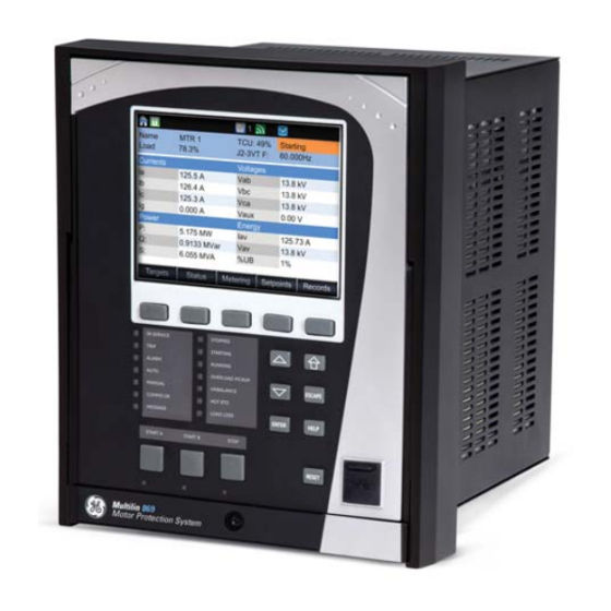
FRONT CONTROL PANEL INTERFACE CHAPTER 3: INTERFACES Front Control Panel Interface The relay provides an easy to use faceplate for menu navigation using 5 navigation pushbuttons and a high quality graphical display. Conveniently located on the panel is a group of 7 pushbuttons for Up/Down value selection, Enter, Home, Escape, Help, and Reset functions. -
Page 75: Working With Graphical Display Pages
CHAPTER 3: INTERFACES FRONT CONTROL PANEL INTERFACE Figure 3-2: 869 Display Page Hierarchy Targets Motor Breakers S tatus Last Trip Data Arc Flash Contact Inputs ches Output Relays Setpoints Device Virtual Inputs System Virtual Outputs Inputs Flex States Outputs Communications Protection Information Monitoring... - Page 76 FRONT CONTROL PANEL INTERFACE CHAPTER 3: INTERFACES Figure 3-3: Typical paging operation from the Main Menu There are two ways to navigate throughout the 869 menu: using the pushbuttons corresponding to the soft tabs from the screen, or by selecting the item from the list of items on the screen using the “Up”...
- Page 77 CHAPTER 3: INTERFACES FRONT CONTROL PANEL INTERFACE Figure 3-5: Keypad Pushbuttons Each Keypad pushbutton serves the following function: The Home pushbutton is used to display the home screen, and all screens defined under the Front Panel/Screens menu as default screens. The Enter pushbutton has a dual function.
-
Page 78: Single Line Diagram
FRONT CONTROL PANEL INTERFACE CHAPTER 3: INTERFACES To change/view an item on from the 869 menus: Use the pushbuttons that correspond to the tabs (Targets, Status, Metering, Setpoints, Records) on the screen to select a menu. Use the Up and Down pushbuttons to highlight an item. Press Enter to view a list of values for the chosen item. -
Page 79: Led Status Indicators
CHAPTER 3: INTERFACES FRONT CONTROL PANEL INTERFACE In 869, the switching device can be configured as Breaker or Contactor ( System > Motor > Setup). If the switching device is configured as Breaker then the SLD Breaker color is specified by the LED assigned for BKR 1 Open. If the switching device is configured as Contactor, then the SLD Contactor color is specified by the LED assigned for Contactor Open. -
Page 80: Home Screen Icons
FRONT CONTROL PANEL INTERFACE CHAPTER 3: INTERFACES • IN SERVICE: – Green color = Relay powered up, passed self-test has been programmed, and ready to serve. This LED indicates that control power is applied, all monitored inputs, outputs, and internal systems are OK, and that the device has been programmed. -
Page 81: Relay Messages
CHAPTER 3: INTERFACES FRONT CONTROL PANEL INTERFACE Figure 3-9: Home Screen Icons Table 3-1: Security Icon Security State Security Icon Color User not logged in Icon is green and locked User logged in Icon is red and unlocked Table 3-2: Setpoint Group Icon Description Identifies the active setpoint group Table 3-3: Wifi Icon... -
Page 82: Self-Test Errors
FRONT CONTROL PANEL INTERFACE CHAPTER 3: INTERFACES Target Messages are displayed in order of their activation, whereas in cases of simultaneous activation, they are displayed in the order outlined below (from highest to lowest priority): Targets generated by pressing programmable pushbutton Targets generated by Contact inputs Targets generated by Protection, Control and Monitoring elements Targets generated by communications. - Page 83 CHAPTER 3: INTERFACES FRONT CONTROL PANEL INTERFACE The Critical Failure Relay (Output Relay 8) is energized when the relay is in-service, and no NOTE: major error is present Under both conditions, the targets cannot be cleared if the error is still active. Figure 3-10: Minor Errors Figure 3-11: Major Errors 869 MOTOR PROTECTION SYSTEM –...
- Page 84 FRONT CONTROL PANEL INTERFACE CHAPTER 3: INTERFACES Table 3-7: Minor Self-test Errors Self-test Error Description of Problem How Often the Test is What to do Performed Message Order Code Error Hardware doesn’t Every 1 second If alert doesn’t self-reset then match order code contact factory.
- Page 85 CHAPTER 3: INTERFACES FRONT CONTROL PANEL INTERFACE Self-test Error Description of Problem How Often the Test is What to do Performed Message Traffic Error Abnormally high Every 1 second Contact site IT department to Primary amount of Broadcast check network for and Uni-cast traffic on malfunctioning devices port 1 or port 4...
-
Page 86: Out Of Service
FRONT CONTROL PANEL INTERFACE CHAPTER 3: INTERFACES Out of Service When the relay is shipped from the factory, the DEVICE IN SERVICE is set to “Not Ready”. The IN SERVICE LED will be orange and the critical fail relay will be de-energized but this will not be classified as a major self-test. -
Page 87: Software Interface
Although settings can be entered manually using the control panel keys, a PC can be used to download setpoints through the communications port. The EnerVista 8 Series Setup software is available from GE Multilin to make this as convenient as possible. With EnerVista 8 Series Setup software running, it is possible to: •... -
Page 88: Installing The Enervista 8 Series Setup Software
SOFTWARE INTERFACE CHAPTER 3: INTERFACES The software can be installed from either the GE EnerVista CD or the GE Multilin website at http://www.gegridsolutions.com/. Installing the After ensuring the minimum requirements indicated earlier, use the following procedure to EnerVista 8 Series install the EnerVista 8 Series Setup software from the enclosed GE EnerVista CD. - Page 89 CHAPTER 3: INTERFACES SOFTWARE INTERFACE Select the complete path, including the new directory name, where the EnerVista 8 Series Setup software is being installed. Click on Next to begin the installation. The files are installed in the directory indicated, the USB driver is loaded into the computer, and the installation program automatically creates icons and adds the EnerVista 8 Series Setup software to the Windows start menu.
-
Page 90: Upgrading The Software
SOFTWARE INTERFACE CHAPTER 3: INTERFACES 13. Select USB as the Interface type. 14. Select the Read Order Code button. Upgrading the The latest EnerVista software and firmware can be downloaded from: Software https://www.gegridsolutions.com/ After upgrading, check the version number under Help > About. If the new version does not display, try uninstalling the software and reinstalling the new versions. - Page 91 CHAPTER 3: INTERFACES SOFTWARE INTERFACE As indicated by the window, the "Quick Connect" feature can quickly connect the software to a front port if the USB is selected in the interface drop-down list. Select “USB” and press the Connect button. Ethernet or WiFi can also be used as the interface for Quick Connect as shown next.
-
Page 92: Configuring Ethernet Communications
FASTPATH: Install and start the latest version of the EnerVista 8 Series Setup software (available from the GE EnerVista CD or Website). See the previous section for the installation procedure. Click on the Device Setup button to open the Device Setup window and click the Add Site button to define a new site. -
Page 93: Connecting To The Relay
CHAPTER 3: INTERFACES SOFTWARE INTERFACE Select “Ethernet” from the Interface drop-down list. This displays a number of interface parameters that must be entered for proper Ethernet functionality. Enter the IP address, slave address, and Modbus port values assigned to the 869 relay (from the SETPOINTS >... -
Page 94: Working With Setpoints & Setpoints Files
SOFTWARE INTERFACE CHAPTER 3: INTERFACES Records Maintenance. Expand the SETPOINTS > DEVICE > FRONT PANEL list item and double click on Display Properties or Default Screens to open the settings window as shown next: The settings window opens with a corresponding status indicator on the lower left of the window. - Page 95 CHAPTER 3: INTERFACES SOFTWARE INTERFACE Clicking the arrow at the end of the box displays a numerical keypad interface that allows the user to enter a value within the setpoint range displayed near the top of the keypad: Click = to exit from the keypad and keep the new value. Click on X to exit from the keypad and retain the old value.
-
Page 96: File Support
SOFTWARE INTERFACE CHAPTER 3: INTERFACES In the Setpoints > System Setup > Voltage Sensing dialog box, click on Save to save the values into the 869. Click YES to accept any changes and exit the window. Click Restore to retain previous values. Click Default to restore Default values. For setpoints requiring an alphanumeric text string (e.g. -
Page 97: Downloading & Saving Setpoints Files
CHAPTER 3: INTERFACES SOFTWARE INTERFACE Downloading & Saving Back up a copy of the in-service settings for each commissioned unit, so as to revert to the Setpoints Files commissioned settings after inadvertent, unauthorized, or temporary setting changes are made, after the settings default due to firmware upgrade, or when the unit has to be replaced. -
Page 98: Creating A New Setpoints File
SOFTWARE INTERFACE CHAPTER 3: INTERFACES Creating a New The software allows the user to create new setpoint files independent of a connected Setpoints File device. These can be uploaded to a relay at a later date. The following procedure illustrates how to create new setpoint files. -
Page 99: Printing Setpoints
CHAPTER 3: INTERFACES SOFTWARE INTERFACE Load the setpoint file to be upgraded into the EnerVista 8 Series Setup software environment as described in the section, Adding Setpoints Files to the Environment. In the File pane, select the saved setpoint file. From the main window menu bar, select the Offline >... -
Page 100: Loading Setpoints From A File
SOFTWARE INTERFACE CHAPTER 3: INTERFACES The Print/Export Options dialog box appears. Select Setpoints in the upper section and select either Include All Features (for a complete list) or Include Only Enabled Features (for a list of only those features which are currently used) in the filtering section and click OK. -
Page 101: Uninstalling Files And Clearing Data
CHAPTER 3: INTERFACES SOFTWARE INTERFACE Select the Offline > Edit Settings File Properties menu item and verify that the corresponding file is fully compatible with the hardware and firmware version of the target relay. If the versions are not identical, see Upgrading Setpoint Files to a New Revision for details on changing the setpoints file version. - Page 102 SOFTWARE INTERFACE CHAPTER 3: INTERFACES Figure 3-12: 869 Quick Setup (Online) tree position Figure 3-13: 869 Quick Setup (Offline) tree position Quick Setup is designed to allow quick and easy user programming. Power system parameters, and settings for some simple overcurrent elements are easily set. The Quick Setup screen is shown as follows: 3–30 869 MOTOR PROTECTION SYSTEM –...
- Page 103 CHAPTER 3: INTERFACES SOFTWARE INTERFACE Figure 3-14: Quick Setup window • Settings names and units can be viewed at this screen. To view the range of the settings, hover the cursor over the setpoint value field. • The user can configure and save the settings as required. •...
-
Page 104: Upgrading Relay Firmware
To upgrade the 869 firmware, follow the procedures listed in this section. Upon successful completion of this procedure, the 869 will have new firmware installed with the factory default setpoints.The latest firmware files are available from the GE Grid Solutions website at http:// www.gegridsolutions.com. - Page 105 CHAPTER 3: INTERFACES SOFTWARE INTERFACE Select the Maintenance > Update Firmware menu item. The following screen appears. Select OK to proceed. The EnerVista 8 Series Setup software requests the new firmware file. Locate the folder that contains the firmware file to load into the 869. The firmware filename has the following format.
- Page 106 SOFTWARE INTERFACE CHAPTER 3: INTERFACES The following screen appears, click YES to proceed with the firmware loading process. After the Boot 2 upload is completed, the EnerVista 8 Series Setup software requests the user reboot the relay. After the Boot 1 upload is completed, the EnerVista 8 Series Setup software again requests the user to reboot the relay.
-
Page 107: Advanced Enervista 8 Series Setup Software Features
CHAPTER 3: INTERFACES SOFTWARE INTERFACE Wait for the Comms upload process to complete. Wait for the Mains upload process to complete. The EnerVista 8 Series Setup software notifies the user when the 869 has finished loading and notifies the user to Cycle power to the relay to complete firmware update. -
Page 108: Transient Recorder (Waveform Capture)
SOFTWARE INTERFACE CHAPTER 3: INTERFACES • The Operate Curves are displayed, which can be edited by dragging the tips of the curves • A Base curve can be plotted for reference, to customize the operating curve. The Blue colored curve in the picture is a reference curve. It can be Extremely Inverse, Definite Time, etc. - Page 109 CHAPTER 3: INTERFACES SOFTWARE INTERFACE • Click on Trigger Waveform to trigger a waveform capture. • To view the captured waveforms, click on the Launch Viewer button. A detailed Waveform Capture window appears as shown below. • Click on the Save button to save the selected waveform to the local PC. A new window appears, requesting the file name and path.
- Page 110 SOFTWARE INTERFACE CHAPTER 3: INTERFACES TRIGGER TIME & DATE Displays the time and date of the Trigger. DELTA VECTOR DISPLAY SELECT CURSOR LINE POSITION Indicates the cursor line position Indicates time difference Click here to open a new graph between the two cursor in time with respect to the to display vectors.
- Page 111 CHAPTER 3: INTERFACES SOFTWARE INTERFACE Preference Button The following window appears: Change the color of each graph as desired, and select other options as required, by checking the appropriate boxes. Click OK to store these graph attributes, and to close the window.
-
Page 112: Protection Summary
SOFTWARE INTERFACE CHAPTER 3: INTERFACES Protection Summary Protection Summary is a single screen which holds the summarized information of different settings from Grouped Elements and Monitoring Elements. The Protection Summary Screen allows the user to: • view the output relay (R3) assignments for the elements •... - Page 113 CHAPTER 3: INTERFACES SOFTWARE INTERFACE 869 MOTOR PROTECTION SYSTEM – INSTRUCTION MANUAL 3–41...
-
Page 114: Offline Settings File Conversion
SOFTWARE INTERFACE CHAPTER 3: INTERFACES Offline Settings File Conversion The EnerVista 8 Series Setup software supports conversion of offline settings files created in the SR Series platform. The feature allows users, who have SR devices, to convert their existing 469 offline settings files to 8 Series files and write them to their 869 devices. The EnerVista 8 Series Setup software reduces the manual effort required when moving from an older product to the 869. -
Page 115: Convert 369 Files
CHAPTER 3: INTERFACES SOFTWARE INTERFACE In the menu taskbar, click on Offline and select the New Settings File item. The following Create New Settings File dialog box appears, which allows for the setpoint file conversion. Select the Firmware Version and Order Code option for the new setpoint file. For future reference, enter some useful information in the Description box to facilitate the identification of the device and purpose for the file. -
Page 116: Results Window
SOFTWARE INTERFACE CHAPTER 3: INTERFACES Figure 3-15: Conversion Report in Offline Window For future reference, the user is advised to take a printout of the conversion report CAUTION: immediately after the conversion. All conversion reports are removed and become inaccessible if the user removes or modifies the converted file from the 8 Series Setup Software. - Page 117 CHAPTER 3: INTERFACES SOFTWARE INTERFACE Although the report shows successful conversion (green checkbox), the settings must still NOTE: be verified before putting the relay in service. 869 MOTOR PROTECTION SYSTEM – INSTRUCTION MANUAL 3–45...
- Page 118 SOFTWARE INTERFACE CHAPTER 3: INTERFACES 3–46 869 MOTOR PROTECTION SYSTEM – INSTRUCTION MANUAL...
-
Page 119: Setpoints Setpoints Main Menu
Grid Solutions 869 Motor Protection System Chapter 4: Setpoints Setpoints Setpoints Main Menu The 869 has a considerable number of programmable setpoints, all of which make the relay extremely flexible. These setpoints have been grouped into a variety of menus which are available from the paths shown below. -
Page 120: Setpoints Entry Methods
Any of these methods can be used to enter the same information. A computer, however, makes entry much easier. Files can be stored and downloaded for fast, error free entry when a computer is used. To facilitate this process, the GE EnerVista CD with the EnerVista 4–2... -
Page 121: Common Setpoints
CHAPTER 4: SETPOINTS SETPOINTS MAIN MENU 8 Series Setup software is supplied with the relay. The relay leaves the factory with setpoints programmed to default values, and it is these values that are shown in all the setpoint message illustrations. At a minimum, the setpoints must be entered for the system to SETPOINTS / SYSTEM... -
Page 122: Logic Diagrams
SETPOINTS MAIN MENU CHAPTER 4: SETPOINTS • TDM: The setting provides a selection for Time Dial Multiplier which modifies the operating times per the selected inverse curve. For example, if an IEEE Extremely Inverse curve is selected with TDM=2, and the fault current is 5 times bigger than the PKP level, operation of the element can not occur before an elapsed time of 2.59 s from Pickup. -
Page 123: Setpoints Text Abbreviations
CHAPTER 4: SETPOINTS SETPOINTS MAIN MENU The relationship between a setpoint and input parameter is indicated by the following symbols: “<” (less than), “>” (greater than), etc. • Pickup and Dropout Time Delays: Shown as a block with indication of two timers – the t (Pickup Delay), and t (Dropout Delay). -
Page 124: Device
DEVICE CHAPTER 4: SETPOINTS Device Figure 4-3: Device Display Hierarchy Custom Configuration Real Time Clock Modbus Protocol Security RS485 Communications Device Wi-Fi Transient Recorder System Ethernet Inputs Data Logger Routing Outputs Fault Report DNP Protocol Protection Event Data DNP/IEC 104 Points List IEC 60870-5-104 Monitoring Flex States... -
Page 125: Custom Configuration
CHAPTER 4: SETPOINTS DEVICE Custom Configuration The custom configuration features allow customization of the 8 Series configurations in such a way that the User eXperience (UX) of the 8 Series platform is further enhanced. Configuration Mode Modern multifunctional Intelligent Electronic Devices (IEDs), such as the 8 Series platform, support a multitude of functions and features which include: Protection and Control (P&C), Asset Monitoring, Flexible Logic Engine (FlexLogic), Records and Reporting, Time Synchronization, Testing/Simulation, etc. - Page 126 DEVICE CHAPTER 4: SETPOINTS Figure 4-4: Comparing the setpoints for Regular and Simplified mode Simplified ..\Current\Phase TOC 1 ..\Current\Phase TOC 1 Item Name Value Unit Item Name Value Unit Function Disabled Function Disabled Signal Input CT Bank 1 -J1 Signal Input CT Bank 1 -J1 Input Phasor...
-
Page 127: Real-Time Clock
CHAPTER 4: SETPOINTS DEVICE Real-time Clock Path: Setpoints > Device > Real Time Clock The 869 is capable of receiving a time reference from several time sources in addition to its own internal clock for the purpose of time-stamping events, transient recorders and other occurrences within the relay. - Page 128 DEVICE CHAPTER 4: SETPOINTS PORT 4(5) PATH DELAY ASYMMETRY Range: -1000 to +1000 ns in steps of 1 ns Default: 0 ns The setting corresponds to “Delay Asymmetry” in PTP, which is used by the peer delay mechanism to compensate for any difference in the propagation delay between the two directions of a link.
-
Page 129: Clock
CHAPTER 4: SETPOINTS DEVICE PTP VLAN ID Range: 0 to 4095 Default: 0 The setting selects the value of the ID field in the 802.1Q VLAN tag in request messages issued by the relay’s peer delay mechanism. It is provided in compliance with PP (Power Profile). -
Page 130: Sntp Protocol
DEVICE CHAPTER 4: SETPOINTS DST START HOUR Range: 0 to 23 Default: 2 DST END MONTH Range: January to December (all months) Default: Not Set DST END WEEK Range: 1st, 2nd, 3rd, 4th, Last Default: Not Set DST END DAY Range: SUN to SAT (all days of the week) Default: Not Set DST END HOUR... -
Page 131: Security
CHAPTER 4: SETPOINTS DEVICE Security The following security features are available: • Basic Security – The basic security feature present in the default offering of the product. • CyberSentry – The feature refers to the advanced security options available as a software option. -
Page 132: Basic Security
DEVICE CHAPTER 4: SETPOINTS • The current limitation for the maximum number of Observer sessions from EnerVista NOTE: is three when the Communications card is present. • When the communications card is not present, a maximum of two Observer sessions may be initiated through EnerVista. - Page 133 CHAPTER 4: SETPOINTS DEVICE This setting is available so that the option of selecting between simple passwords and complex ones is provided. • The setting is only available to Administrator. • By default password complexity is disabled. • When password complexity is enabled, it follows the rules defined in the Password Complexity section.
-
Page 134: Cybersentry
DEVICE CHAPTER 4: SETPOINTS CyberSentry The following features are supported in the CyberSentry feature: • CyberSentry provides secure tunneling of MODBUS communications between itself and the EnerVista setup software, using SSH. • All the roles supported in the Basic Security are supported. •... - Page 135 CHAPTER 4: SETPOINTS DEVICE SECURITY SETTINGS STRUCTURE The figure below shows the location of the Security settings in the device display hierarchy. Figure 4-7: Security Settings Structure SECURITY SETTINGS LOGIN Range: Administrator, Operator, Observer Default: Observer The setting allows a user to login with a specific role. –...
- Page 136 DEVICE CHAPTER 4: SETPOINTS LOGOUT Range: Yes, No Default: No This setting logs out the current user. When logging out from the panel, a switch to the Observer role is performed. DEVICE AUTHENTICATION Range: Yes, No Default: Yes Device authentication setting offers the option to disable or enable this type of authentication.
- Page 137 CHAPTER 4: SETPOINTS DEVICE ENABLE PASSWORD COMPLEXITY Range: Disabled, Enabled Default: Disabled This setting is available to provide the option of selecting between simple passwords and complex ones. The following conditions apply: – The setting is only available to Administrator –...
- Page 138 DEVICE CHAPTER 4: SETPOINTS – Each password change menu has two settings: New Password and Confirm Password. – With password complexity enabled, each setting may take 6 to 20 alphanumeric characters. With password complexity disabled, each setting takes 1 to 20 alphanumeric characters.
- Page 139 CHAPTER 4: SETPOINTS DEVICE RADIUS SETTINGS The following are settings that need to be configured through EnerVista, in order to set up communication with a Radius server on 869. For configuring the RADIUS server itself, consult the RADIUS documentation. An example is provided, see Communications Guide. Table 4-3: Radius Settings Setting Description...
- Page 140 DEVICE CHAPTER 4: SETPOINTS Event Record Level Description LOGOUT, ORIGIN, TIMESTAMP: Warning (4) An event to indicate when a certain role logged out or timed out. RADIUS_UNREACH, ORIGIN, Critical (2) RADIUS server is unreachable. Origin: RADIUS TIMESTAMP: server IP address and port number. CLEAR_EVENT_RECORDS, Warning (4) Clear event records command was issued.
-
Page 141: Communications
CHAPTER 4: SETPOINTS DEVICE Communications The 8 Series relays have a two-stage communications capability. The base CPU supports Modbus protocol through the Ethernet, USB, serial and WiFi port. In addition, the base CPU also supports IEC 103, DNP serial, and TFTP protocol. Once the communications module option is added to the base, the base Ethernet port becomes disabled but the two Ethernet ports on the communications module have enhanced communications capabilities such as IEC61850, IEC62439 parallel redundancy protocol and IEEE 1588 Precision Time... - Page 142 DEVICE CHAPTER 4: SETPOINTS MODBUS SLAVE ADDRESS Range: 1 to 254 in steps of 1 Default: 254 For the RS485 ports each 869 must have a unique address from 1 to 254. Address 0 is the broadcast address to which all Modbus slave devices listen. Addresses do not have to be sequential, but no two devices can have the same address, otherwise conflicts resulting in errors occur.
- Page 143 CHAPTER 4: SETPOINTS DEVICE The slave response to this function code is the slave address, function code, a count of the number of data bytes to follow, the data itself and the CRC. Each data item is sent as a two byte number with the high order byte sent first.
- Page 144 DEVICE CHAPTER 4: SETPOINTS Table 4-7: Data Written to Relay to Login as Administrator Description Memory Map Address Value to be written Role Characters 1 and 2 62242 F322 16740 4164 Role Characters 3 and 4 62243 F323 28009 6D69 Role Characters 5 and 6 62244 F324...
- Page 145 CHAPTER 4: SETPOINTS DEVICE Table 4-11: Examples of Command values Command Value Value Description Reset Clear All Records Clear Events Clear Energy Use Data 4096 Force Virtual Input 1 Function Format for “Clear All” command: Table 4-12: Function Format for “Clear All” command Slave # Function Data Starting...
-
Page 146: Rs485
DEVICE CHAPTER 4: SETPOINTS RS485 On the rear card 8 Series relays are equipped with one RS485 serial communication port and one 10/100 Mbps Ethernet port. The RS485 port has settings for baud rate and parity. It is important that these parameters agree with the settings used on the computer or other equipment connected to this port. - Page 147 CHAPTER 4: SETPOINTS DEVICE WiFi IP Address / Subnet Mask The default IP address is 192.168.0.x, where x is calculated as: X = (modulo 242 of the last 3 digits of the serial number) + 12 Example: A unit has a serial number of MJ3A16000405, the default IP address would be 192.168.0.175 (where 405 mod 242 = 163 + 12 = 175).
- Page 148 DEVICE CHAPTER 4: SETPOINTS WiFi State WiFi Icon Color Disabled Icon is grey and crossed by a red line Disconnected Grey Connecting Yellow Connected Green WiFi Events Event Description WiFi Connected This event is recorded to indicate a network connect. WiFi Disconnected This event is recorded to indicate a network disconnect.
-
Page 149: Ethernet Ports
CHAPTER 4: SETPOINTS DEVICE Figure 4-8: Example of WiFi Deployment The USB parameters are as follows: IP Address: 172.16.0.2 IP Mask: 255.255.255.0 IP Gateway: 172.16.0.1 Whenever the device is rebooted, the USB cable needs to be unplugged and plugged in FASTPATH: again for proper communication to be established over USB. - Page 150 DEVICE CHAPTER 4: SETPOINTS Network Settings Menu The following are the network settings menu of the 869 to accommodate the features of the 869 product. If the communications card is installed network port 1 is no longer available. When using more than one Ethernet port, configure each to belong to a different network or subnet using the IP addresses and mask, else communication becomes unpredictable when more than one port is configured to the same subnet.
-
Page 151: Routing
CHAPTER 4: SETPOINTS DEVICE PRT4 OPERATION Range: Independent, LLA, PRP Default: Independent This setting determines the mode of operation for ports 4 and 5: INDEPENDENT, LLA or PRP. INDEPENDENT operation: ports 4 and 5 operate independently with their own MAC and IP address. - Page 152 DEVICE CHAPTER 4: SETPOINTS PATH: Setpoints>Device>Communications>Routing>Static RT1 (2 to 6) RT1 (2,3,4,5,6) DESTINATION Range: Standard IPV4 network address format (0.0.0.1 to 223.255.255.254) Default: 127.0.0.1 This setting sets the destination IPv4 route. This setting is available only if the communications card is present. RT1 (2,3,4,5,6) MASK Range: Standard IPV4 network mask format Default: 255.0.0.0...
- Page 153 CHAPTER 4: SETPOINTS DEVICE This is an example of a good configuration: RtDestination= 10.1.1.0; Rt Mask= 255.255.255.0 This is an example of a bad configuration: RtDestination = 10.1.1.1; Rt Mask= 255.255.255.0 The route destination must not be a connected network. The route gateway must be on a connected network.
-
Page 154: Dnp Protocol
DEVICE CHAPTER 4: SETPOINTS Behavior: One static network route was added to the destination 10.1.3.0/24, where a laptop running EnerVista is located. This static route uses a different gateway (10.1.2.1) than the default route. This gateway is the address of Router 2, which is “aware” of destination 10.1.3.0 and is able to route packets coming from the 8 Series device and destined to EnerVista. -
Page 155: Dnp / Iec104 Point Lists
CHAPTER 4: SETPOINTS DEVICE DNP Unsol Resp Dest Addr Range: 1 to 65519 in steps of 1 Default: 1 Sets the DNP address to which all unsolicited responses are sent. The IP address to which unsolicited responses are sent is determined by the 869 from the current TCP connection or the most recent UDP message. - Page 156 DEVICE CHAPTER 4: SETPOINTS Up to 32 analog input points can be configured for the DNP or IEC 60870-5-104 protocols. The menu path for the analog input point (DNP) or MME points (IEC 60870-5-104) is shown below. Path: Setpoints > Device > Communications > DNP/IEC104 Point Lists > Analog Input / MME Points Analog IP Point 0 Entry Point 0 Scale Factor...
- Page 157 CHAPTER 4: SETPOINTS DEVICE Request Function Codes supported: 1 (read), 22 (assign class) Static Variation reported when variation 0 requested: 2 (Binary Input with status), Configurable Change Event Variation reported when variation 0 requested: 2 (Binary Input Change with Time), Configurable Change Event Scan Rate: 8 times per power system cycle Change Event Buffer Size: 1024 Default Class for All Points: 1...
-
Page 158: Iec 60870-5-104
DEVICE CHAPTER 4: SETPOINTS 13 Digital Counter 14 14 Digital Counter 15 15 Digital Counter 16 ANALOG INPUTS It is important to note that 16-bit and 32-bit variations of analog inputs are transmitted through DNP as signed numbers. Even for analog input points that are not valid as negative values, the maximum positive representation is 32767 for 16-bit values and 2147483647 for 32-bit values. -
Page 159: Iec 60870-5-103
CHAPTER 4: SETPOINTS DEVICE Each Measured value has a Parameter of measured value (P_ME_NB) associated to its threshold. The IEC 60870-5-104 Deadbands settings are used to determine when to trigger spontaneous responses containing M_ME_NB_1 analog data. Each setting represents the threshold value for each M_ME_NB_1 analog point. -
Page 160: Iec 61850
DEVICE CHAPTER 4: SETPOINTS IEC103 Sync Timeout Range: 0 to 3600 seconds in steps of 1 Default: 0 To view the list of binary inputs, see the 869 Flexlogic Operands table in the Setpoints/ FlexLogic section of the individual 869 instruction manual. The user must pay attention when configuring the function type and information number FASTPATH: of the different points, because they must be unique. - Page 161 CHAPTER 4: SETPOINTS DEVICE – Select the required settings from the different tab displays (in the configurator screen) to complete the IEC 61850 configuration. Online right-click option – Select any online relay and right click on the selected “tree” item. More options become available for selection, as shown in the next examples.
-
Page 162: Remote Modbus Device
DEVICE CHAPTER 4: SETPOINTS OFFLINE SETTINGS FILE The Generate ICD file menu option generates a default ICD file with the respective order code option and saves the file to the path the user has selected previously. IEC 61850 Configurator Details The IEC61850 Configurator allows the user to edit all sections of the IEC61850 CID and ICD file. - Page 163 CHAPTER 4: SETPOINTS DEVICE SLAVE ADDRESS Range: 1 to 254 in steps of 1 Default: 254 MODBUS PORT Range: 0 to 10000 in steps of 1 Default: 502 POLL RATE Range: OFF, 3 to 120 minutes in steps of 1 Default: 3 minutes TRIGGER Range: Any FlexLogic Operand...
-
Page 164: Transient Recorder
DEVICE CHAPTER 4: SETPOINTS Transient Recorder The Transient Recorder contains waveforms captured at the same sampling rate as the other relay data at the point of trigger. By default, data is captured for all AC current and voltage inputs available on the relay as ordered. Transient record is generated upon change of state of at least one of the assigned triggers: “Trigger Source”, “Trigger on Pickup”, “Trigger on Operate”, “Trigger on Alarm”, or “Trigger on Trip”. - Page 165 CHAPTER 4: SETPOINTS DEVICE TRIGGER POSITION Range: 0 to 100% in steps of 1% Default: 20% This setting indicates the location of the trigger with respect to the selected length of record. For example at 20% selected trigger position, the length of each record will be split on 20% pre-trigger data, and 80% post-trigger data.
-
Page 166: Data Logger
DEVICE CHAPTER 4: SETPOINTS Data Logger The data logger samples and records up to 16 analog parameters at rate defined by the user. All data is stored in non-volatile memory, where the information is retained upon a relay control power loss. The data logger can be configured with a few channels over a long period of time, or with larger number of channels for a shorter period of time. - Page 167 CHAPTER 4: SETPOINTS DEVICE RATE Range: 1 cycle, 1 second, 30 seconds, 1 minute, 15 minutes, 30 minutes, 1 hour Default: 1 minute This setting selects the time interval at which the actual value is recorded. CHANNEL 1(16) SOURCE Range: Off, Any FlexAnalog parameter Default: Off This setpoint selects the metering analog value that is to be recorded in Channel 1(16) of the data log.
-
Page 168: Fault Reports
DEVICE CHAPTER 4: SETPOINTS Figure 4-10: Data Logger Storage Capacity Fault Reports The 869 relay supports up to 15 fault reports. The trigger conditions and the analog quantities to be stored are entered in this menu. When enabled, this function monitors the pre-fault trigger. The pre-fault data are stored in the memory for prospective creation of the fault report on the rising edge of the pre-fault trigger. - Page 169 CHAPTER 4: SETPOINTS DEVICE • Pre-fault values for all programmed analog channels (one cycle before pre-fault trigger) • Fault values of all programmed analog channels (one cycle after the fault trigger) Each Fault Report created can be saved as a text file using the EnerVista 8 Series Setup software.
-
Page 170: Event Data
DEVICE CHAPTER 4: SETPOINTS Event Data The Event Data feature stores 64 FlexAnalog quantities each time an event occurs. The relay is able to capture a maximum of 1024 records. The Event Data behaviour matches that of the Event Recorder. This is a Platform feature and a ‘Basic’ option so it has no dependencies. - Page 171 CHAPTER 4: SETPOINTS DEVICE LED 5 (6-17) TRIGGER Range: Off, Any operand from the list of FlexLogic operands This setpoint requires the assigning of a FlexLogic operand to trigger the selected LED upon operation. LED 5 (6-17) TYPE Range: Self-reset, Latched The setpoint defines the type of LED indication as either Self-Reset (the LED resets after the FlexLogic operand drops out), or Latched (the LED stays latched upon dropping out of the FlexLogic operand).
- Page 172 DEVICE CHAPTER 4: SETPOINTS LED 11 - Programmable Name: OVERLOAD - Range: Up to 13 alphanumeric characters Color: Green Trigger: Motor Overload Type: Self-reset LED 12 - Programmable Name: START INHIBIT - Range: Up to 13 alphanumeric characters Color: Orange Trigger: Start Inhibit Type: Self-reset LED 13 - Programmable...
-
Page 173: Programmable Pushbuttons
CHAPTER 4: SETPOINTS DEVICE Programmable Pushbuttons The user-programmable pushbuttons provide an easy and error-free method of entering digital state (on, off) information. Three pushbuttons are available for programming. The digital state of the pushbuttons can be entered only locally (by directly pressing the front panel pushbutton). - Page 174 DEVICE CHAPTER 4: SETPOINTS Pushbutton states can be logged by the Event Recorder and displayed as Target Messages. In latched mode, user-defined messages can also be associated with each pushbutton and displayed when the pushbutton is ON or changing to OFF. Path: Setpoints >...
- Page 175 CHAPTER 4: SETPOINTS DEVICE expired, the default message or other active target message is displayed. The instantaneous Reset of the flash message will be executed if any relay front panel button is pressed or if any new target or message becomes active. The PUSHBTN 1 OFF TEXT setting is linked to PUSHBUTTON 1 OFF operand and will be displayed in conjunction with PUSHBTN 1 ID only if the pushbutton element is in “Latched”...
- Page 176 DEVICE CHAPTER 4: SETPOINTS Figure 4-11: Pushbuttons Logic Diagram 4–58 869 MOTOR PROTECTION SYSTEM – INSTRUCTION MANUAL...
-
Page 177: Front Panel
CHAPTER 4: SETPOINTS DEVICE Front Panel The 869 relay provides an easy-to-use faceplate for menu navigation using 5 navigation pushbuttons and a high quality graphical display. Conveniently located on the panel is a group of 7 pushbuttons for Up/Down value selection, and the “Enter,” “Home,” “Escape,” “Help,”... -
Page 178: Default Screens
DEVICE CHAPTER 4: SETPOINTS Default Screens The 8 Series relay provides the convenience of configuring and displaying up to three default screens from a predefined list. The user selects each type of screen to display, and programs the display time. The sequence of displaying the screens starts after the time of inactivity programmed in the Message Timeout time setpoint: no PB has been pressed, no target message is present. -
Page 179: Installation
CHAPTER 4: SETPOINTS DEVICE Installation Path: Setpoints > Device > Installation DEVICE NAME Range: Up to 13 alphanumeric characters An alphanumeric name may be assigned to the device. DEVICE IN SERVICE Default: Not Ready Range: Not Ready, Ready The relay is defaulted to the “Not Ready” state when it leaves the factory. This safeguards against the installation of a relay whose settings have not been entered. -
Page 180: System
SYSTEM CHAPTER 4: SETPOINTS System Figure 4-12: System Display Hierarchy 4–62 869 MOTOR PROTECTION SYSTEM – INSTRUCTION MANUAL... -
Page 181: Current Sensing
CHAPTER 4: SETPOINTS SYSTEM Current Sensing The Current Sensing menu provides the setup menu for the Current Transformers (CTs) connected to the 869 terminals. The setup of the three-phase CTs, and the Ground CT requires a selection of primary CT ratings. The secondary CT ratings are selected in the 869 Order code. -
Page 182: Voltage Sensing
SYSTEM CHAPTER 4: SETPOINTS Voltage Sensing The Voltage Sensing menu provides the setup for all VTs (PTs) connected to the relay voltage terminals. The 869 can be connected to 4 VTs, i. e. three-phase VTs from either a Wye (Star) or a Delta connection, and one auxiliary VT. -
Page 183: Power System
CHAPTER 4: SETPOINTS SYSTEM For example, on a system of 13.8kV nominal primary voltage, and a 14400:120 volt VT in a Delta connection, the secondary voltage would be 115V, i.e. (13800/14400)*120. For a Wye connection, the voltage value entered must be the phase to neutral voltage which would be 115/√3 = 66.4 V. -
Page 184: Motor
SYSTEM CHAPTER 4: SETPOINTS Motor Setup The following settings reflect the design and configuration of the motor that the relay will protect. Note that some protection elements are dependent on these settings for correct operation. Path: Setpoints > System > Motor > Setup MOTOR FULL LOAD AMPS (FLA) Range: 1 to 5000 A in steps of 1 A Default: 100 A... - Page 185 CHAPTER 4: SETPOINTS SYSTEM to zero, and resets all Trips and Alarms so that a hot motor may be restarted. However, a Restart Delay inhibit lockout will remain active (it may be used as a backspin timer) and any trip condition that remains (such as a hot RTD) will still cause a trip. In the event of a real emergency, the Emergency Restart input must remain asserted until the emergency is over.
- Page 186 SYSTEM CHAPTER 4: SETPOINTS Figure 4-13: Motor Load Averaging Filter for VFD and Cyclic Load Motor Applications 4–68 869 MOTOR PROTECTION SYSTEM – INSTRUCTION MANUAL...
- Page 187 CHAPTER 4: SETPOINTS SYSTEM NUMBER OF POLES Range: 2 to 64 in steps of 2 Default: 2 This setting represents the number of poles of the motor. MAX. ACCELERATION TIME Range: 1.00 to 180 s in steps of 0.01 s Default: 10.00 s This setting specifies the maximum acceleration time.
- Page 188 SYSTEM CHAPTER 4: SETPOINTS SPEED2 SWITCH 2-1 DELAY Range: 0.00 to 600.00 s in steps of 0.01 s Default: 5.00 s This setting specifies the time delay to transfer from high to low speed. This allows the motor to slow down before energizing at low speed. When the motor is switched from high speed to low speed, the Speed2 Trans 2-1 Op FlexLogic operand is set for time defined by the Speed2 Switch 2-1 Delay setting to allow inputs for control logic of contactors and breakers at both speeds.
-
Page 189: Variable Frequency Drives
CHAPTER 4: SETPOINTS SYSTEM Variable Frequency Path: Setpoints > System > Motor > VFD Drives Some Variable Frequency Drives (VFD), for example pulse width modulated drives, generate significant distortion in voltages introducing harmonics. However, distortion due to these harmonics is not as significant in currents as in voltages. The functionality of various 869 protection elements is made adaptive to the VFD motor applications depending on the system configurations. - Page 190 SYSTEM CHAPTER 4: SETPOINTS However, this filter when used for the VFD motor application running at low frequency results in a very long Trip/Alarm times delay. For example: if setpoint Motor Load Filter Interval is set 10 cycles and motor is running at 20Hz (tracking frequency), then the Trip/ Alarm delay is increased by 0.5 sec.
- Page 191 CHAPTER 4: SETPOINTS SYSTEM Analyze the captured waveform in Step 4 to see if the estimate value from Step 2 is appropriate enough to mitigate the oscillations. If needed, repeat Steps 1-4 in order to achieved the appropriate value of the setpoint “Motor Load Filter Interval” until oscillations become negligible.
- Page 192 SYSTEM CHAPTER 4: SETPOINTS Figure 4-15: Typical Motor Applications with VFD and Bypass Switch Busbar Busbar Switching Device Status Switching Device Status Bypass Switch Status Contact Inputs Contact Inputs Motor Motor (A) Motor powered through the VFD (B) Motor powered through the VFD with Bypass Switch 4–74 869 MOTOR PROTECTION SYSTEM –...
- Page 193 CHAPTER 4: SETPOINTS SYSTEM Figure 4-16: VFD Logic 869 MOTOR PROTECTION SYSTEM – INSTRUCTION MANUAL 4–75...
-
Page 194: Preset Values
SYSTEM CHAPTER 4: SETPOINTS Preset Values In 869, user can preset the following actual value accumulators. When accumulator is preset with a new value, the 869 overwrites previous actual value and continues accumulation starting from the new value. The accumulated value is displayed in Status or Metering. -
Page 195: Switching Device
CHAPTER 4: SETPOINTS SYSTEM Switching Device The 869 supports two types of motor switching devices: breakers and contactors. A breaker operation is controlled by two coils labeled “Trip” and “Close”. Each of them has to be separately energized with a short pulse in order to change the state of the breaker. A contactor operation is controlled by a single coil. - Page 196 SYSTEM CHAPTER 4: SETPOINTS CONTACT INPUT 52b Range: Off, Any Contact Input Default: Off Select the contact input connected to the breaker or contactor auxiliary contact 52b. CONNECTED Range: Off, Any Contact Input Default: Off Select a contact input to show whether the breaker or contactor is connected (Racked- in, or disconnect switches switched-on) or disconnected (racked-out, or disconnect switches switched-off) to the system.
- Page 197 CHAPTER 4: SETPOINTS SYSTEM 869 MOTOR PROTECTION SYSTEM – INSTRUCTION MANUAL 4–79...
-
Page 198: Flexcurves
SYSTEM CHAPTER 4: SETPOINTS FlexCurves The relay incorporates four programmable FlexCurves - FlexCurve A, B, C and D. The points for these curves are defined by the user in the EnerVista program. User-defined curves can be used for Time Overcurrent protection in the same way as IEEE, IAC, ANSI, and IEC curves. - Page 199 CHAPTER 4: SETPOINTS SYSTEM RESET TIME ms RESET TIME ms OPERATE TIME OPERATE TIME OPERATE TIME OPERATE TIME 0.20 0.76 12.5 0.25 0.78 13.0 0.30 0.80 13.5 0.35 0.82 14.0 0.40 0.84 14.5 0.45 0.86 15.0 0.48 0.88 15.5 0.50 0.90 16.0 0.52...
-
Page 200: Inputs
INPUTS CHAPTER 4: SETPOINTS Inputs Figure 4-18: Inputs Display Hierarchy Contact Inputs The 869 relay is equipped with a number of Contact Inputs, depending on the Order Code, which can be used to provide a variety of functions such as for circuit breaker control, external trips, blocking of protection elements, etc. - Page 201 CHAPTER 4: SETPOINTS INPUTS VOLTAGE THRESHOLD /Slot F/G/H Range: 17, 33, 84, 166 VDC Default: 33 VDC The setting determines the minimum voltage required to detect a closed Contact Input. The value is selected according to the following criteria: 17 for 24 V sources, 33 for 48 V sources, 84 for 110 to 125 V sources and 166 for 250 V sources.
- Page 202 INPUTS CHAPTER 4: SETPOINTS figure below). The update is performed at the beginning of the protection pass so all protection and control functions, as well as FlexLogic™ equations, are fed with the updated states of the Contact Inputs. The FlexLogic™ operand response time to the Contact Input change is related to the debounce time setting plus up to one protection pass (variable and depending on system frequency if frequency tracking enabled).
-
Page 203: Virtual Inputs
CHAPTER 4: SETPOINTS INPUTS Virtual Inputs The 869 relay is equipped with 32 Virtual Inputs that can be individually programmed to respond to input signals from the keypad or from communications protocols. This has the following advantages over Contact Inputs only: •... - Page 204 INPUTS CHAPTER 4: SETPOINTS Figure 4-20: Virtual Inputs Scheme Logic SETPOINTS VIRTUAL INPUT 1 FUNCTION : Disabled=0 Enabled =1 Virtual Input 1 to ON =1 LATCH FlexLogic Operands Reset- Virtual Input 1 to OFF =0 VI 1 ON Dominant SETPOINTS VIRTUAL INPUT 1 TYPE: Latched...
-
Page 205: Analog Inputs
CHAPTER 4: SETPOINTS INPUTS Analog Inputs Description The 8 Series relay can monitor any external quantity from the DcmA transducers such as vibration, field current, pressure, tap position etc., using ‘Analog Inputs’. Any one of the standard transducer output ranges: 0 to 1 mA, 0 to 5 mA, 0 to 10mA, 0 to 20 mA, or 4 to 20 mA can be connected to the Analog Input terminals. - Page 206 INPUTS CHAPTER 4: SETPOINTS MAX VALUE Range: -500000 to 500000 units in steps of 1 unit Default: 0 For the MAXIMUM VALUE setpoint, enter the value which corresponds to the maximum output value of the transducer. For example, if a temperature transducer which outputs 4 to 20 mA for temperatures 0 to 250°C is connected to the analog input, then enter “250”...
- Page 207 CHAPTER 4: SETPOINTS INPUTS ALARM FUNCTION Range: Disabled, Alarm, Latched Alarm Default: Disabled The selection of Alarm or Latched Alarm setting enables the alarm function. ALARM TYPE Range: Over, Under Default: Over This setting determines if alarm pickup will occur when the analog input is over or under the programmed threshold.
- Page 208 INPUTS CHAPTER 4: SETPOINTS TARGETS Range: Disabled, Self-Reset, Latched Default: Latched The selection of the Self-Reset or Latched setting enables the targets of the Analog Input function. 4–90 869 MOTOR PROTECTION SYSTEM – INSTRUCTION MANUAL...
- Page 209 CHAPTER 4: SETPOINTS INPUTS Figure 4-21: Analog Input Threshold Logic Diagram 869 MOTOR PROTECTION SYSTEM – INSTRUCTION MANUAL 4–91...
-
Page 210: Remote Inputs
INPUTS CHAPTER 4: SETPOINTS Remote Inputs Remote inputs provide a means of exchanging digital state information between Ethernet- networked devices supporting IEC 61850. Remote inputs that create FlexLogic operands at the receiving relay are extracted from GOOSE messages originating in remote devices. Remote input 1 must be programmed to replicate the logic state of a specific signal from a specific remote device for local use. -
Page 211: Outputs
CHAPTER 4: SETPOINTS OUTPUTS Outputs Figure 4-22: Outputs Display Hierarchy Output Relays The 869 relay is equipped with a number of electromechanical output relays specified at the time of ordering. Each of the available modules for slot F provides 5 contact outputs the first two of which are designated as Trip and Close (Relay 1 “Trip”, Relay 2 “Close”). -
Page 212: Output Relay 1 (F1) Trip
OUTPUTS CHAPTER 4: SETPOINTS can be reset with a reset command. If the Self-reset type is selected, the output relay is energized when the corresponding element operates and it stays energized until the element drops out. 52a Contact Configured 52b Contact Configured Relay Operation Trip Relay and Close Relays continue operating until the switching device is... - Page 213 CHAPTER 4: SETPOINTS OUTPUTS OPERATION Range: Non-Failsafe, Failsafe Default: Non-Failsafe Failsafe operation causes the output relay to be energized when the Trip condition signal is low and de-energized when the same signal is high. A failsafe relay also changes state (if not already activated by an operand driving this output relay) when control power is removed from the 869.
- Page 214 OUTPUTS CHAPTER 4: SETPOINTS Figure 4-23: Relay 1 “TRIP” logic diagram 4–96 869 MOTOR PROTECTION SYSTEM – INSTRUCTION MANUAL...
-
Page 215: Output Relay 2 (F4) Programmed As Close
CHAPTER 4: SETPOINTS OUTPUTS Output Relay 2 (F4) Output Relay 2 (F4) is labeled CLOSE/AUX on the wiring diagram. As suggested by that programmed as Close name, it can be used as a Close relay or an Auxiliary relay. The selection can be made in Setpoints >... -
Page 216: Auxiliary Output Relays
OUTPUTS CHAPTER 4: SETPOINTS Auxiliary Output The 869 relay is equipped with Auxiliary Output relays. The I/O cards, and a number of Relays auxiliary output relays are defined at the time of relay ordering. The Auxiliary Relays can be energized directly from the menu of the protection or control feature or from their respective menus by assigning a FlexLogic operand (trigger) under the setpoint “Aux Rly # Operate”. -
Page 217: Output Relay 3 (F7) Start Inhibit
CHAPTER 4: SETPOINTS OUTPUTS OPERATE Range: Off, Any FlexLogic operand Default: Off This setpoint provides a selection of any operand from the list of FlexLogic or communications, which can be used to energize the auxiliary output relay. TYPE Range: Self-Reset, Latched, Pulsed Default: Pulsed If Self-Reset is selected, the output relay is energized as long as the element is in operating mode, and resets when the element drops out. -
Page 218: Virtual Outputs
OUTPUTS CHAPTER 4: SETPOINTS Virtual Outputs The 869 relay is equipped with 32 virtual outputs that may be assigned for use via FlexLogic. Virtual outputs not assigned for use are set to OFF (Logic 0). A name can be assigned to each virtual output. Any change of state to a virtual output can be logged as an event if programmed to do so. -
Page 219: Analog Outputs
CHAPTER 4: SETPOINTS OUTPUTS Analog Outputs Description Depending on the order code, the 8 Series relay supports one optional DC analog card. The Analog card has 4 analog inputs and 7 analog outputs. There are three Analog Output channel scenarios for analog minimum and maximum output range: A, B, and C shown in the figure below. - Page 220 OUTPUTS CHAPTER 4: SETPOINTS MAXIMUM VALUE Range: Populates per selection of the analog parameter Default: 0 This setting defines the maximum value of the analog output quantity. It populates based on the selection of the analog parameter. Each channel can be programmed to represent a FlexAnalog parameter available in the respective 8 Series relay.
-
Page 221: Protection
CHAPTER 4: SETPOINTS PROTECTION Protection The 869 protection elements are organized in six (6) identical setpoint groups: Setpoint Group 1 to Setpoint Group 6. Figure 4-27: Protection Display Hierarchy Each Setpoint Group has the same protection functions, depending on the relay order code. - Page 222 PROTECTION CHAPTER 4: SETPOINTS • Ground Time Overcurrent • Ground Instantaneous Overcurrent • Negative Sequence Instantaneous Overcurrent Voltage Elements • Phase Reversal • Phase Undervoltage • Phase Overvoltage • Auxiliary Overvoltage • Auxiliary Undervoltage • Neutral Overvoltage • Negative Sequence Overvoltage Power Elements •...
-
Page 223: Motor Elements
CHAPTER 4: SETPOINTS PROTECTION Motor Elements Figure 4-28: Motor Elements Display Hierarchy Percent Differential Thermal Model Device Current Unbalance Motor System Mechanical Jam Current Inputs Undercurrent Group 1 Data Capture Voltage Outputs Loss of Excitation Group 2 Data Capture Power Protection Overload Alarm Group 3... - Page 224 PROTECTION CHAPTER 4: SETPOINTS Where: I is the current phasor of the terminal side CTs (J1-CT bank), in per unit normalized to the reference CT nominal; I is the current phasor of the neutral side CTs (K1-CT bank), in per unit normalized to the reference CT nominal; They are calculated based on the following equations: Eq.
- Page 225 CHAPTER 4: SETPOINTS PROTECTION Each pair of measured restraining and differential currents represents a point on the previous figure: Percent Differential Characteristic. If this point is located above the limit line (area labeled “Operate”), then the differential flag is set (DIF=1). If the point is located below or on the limit line (area labeled “Block”), then the differential flag is reset (DIF=0).
- Page 226 PROTECTION CHAPTER 4: SETPOINTS under normal operating conditions. A setting of 0.1 to 0.3 pu is generally recommended. The CT base of the setting is the reference CT nominal (the CT with the maximum primary current rating) for the internal summation method, and the core balance CT nominal for the core balance method.
- Page 227 CHAPTER 4: SETPOINTS PROTECTION OUTPUT RELAY X Range: Do Not Operate, Operate Default: Do Not Operate EVENTS Range: Disabled, Enabled Default: Enabled TARGETS Range: Disabled, Self-reset, Latched Default: Latched The values of the setpoints for minimum pickup, Break 1 and Break 2 are expressed in NOTE: terms of CT reference.
- Page 228 PROTECTION CHAPTER 4: SETPOINTS sets the saturation flag (SAT = 1). The algorithm returns to the "NORMAL" state if the differential current is below the first slope, S1, for more than 200 ms. When in the "EXTERNAL FAULT" state, the algorithm goes into the "EXTERNAL FAULT & CT SATURATION"...
- Page 229 CHAPTER 4: SETPOINTS PROTECTION Figure 4-31: Percent Differential logic diagram 869 MOTOR PROTECTION SYSTEM – INSTRUCTION MANUAL 4–111...
-
Page 230: Thermal Model
PROTECTION CHAPTER 4: SETPOINTS Thermal Model The Thermal model is the primary protective function of the 869. It consists of five key elements: • Thermal model curve (overload) • Overload pickup level • Unbalance biasing of the motor current while the motor is running •... - Page 231 CHAPTER 4: SETPOINTS PROTECTION Voltage Dependent Function setting is “Enabled”. The algorithm uses memory in the form of a register called Thermal Capacity Used. This register is updated every power cycle using the following equation: Eq. 9 Where — represents the time coordinate on the time-current overload curve, trip corresponding to the equivalent motor current detected within any power cycle period of motor overload.
- Page 232 PROTECTION CHAPTER 4: SETPOINTS Pickup 869 STANDARD “Motor” Curve TD MULTIPLIERS Level x 10 x 11 x 12 x 13 x 14 x 15 7.00 1.82 3.64 5.46 7.29 9.11 10.93 12.75 14.57 16.39 18.22 20.04 21.86 23.68 25.50 27.32 7.50 1.58 3.16...
- Page 233 CHAPTER 4: SETPOINTS PROTECTION CURVE EFFECT Range: Cutoff, Shift Default: Cutoff This setting affects the trip time thermal curves when the Overload Curve is selected as “Motor”. This setting takes into account the design of the machine with respect to overload capability as determined by the overload (service) factor.
- Page 234 PROTECTION CHAPTER 4: SETPOINTS CURVE k FACTOR Range: 1.00 to 1.50 in steps of 0.05 Default: 1.10 The setting applies only to the IEC motor curve and is applied as described below. Refer to the IEC 255-8 standard for additional details on its application. If “IEC”...
- Page 235 CHAPTER 4: SETPOINTS PROTECTION Voltage dependent overload curves are not applicable. The motor status is evaluated using motor FLA and the IEC Curve k Factor setting. TD MULTIPLIER Range: 1.00 to 25.00 in steps of 0.01 - when thermal model curve is Motor, 0.00 to 600.00 in steps of 0.01 - when thermal model curve is Flexcurve Default: 1.00 The multiplier is used to shift the overload curve on the time axis to create a family of the...
- Page 236 PROTECTION CHAPTER 4: SETPOINTS FLEXCURVES In some applications, the shape of the motor thermal damage curve substantially deviates from the standard. Furthermore, the characteristics of the starting (locked rotor and acceleration) and running thermal damage curves may not correspond smoothly. In these cases, it may be necessary to use a custom curve so the motor can be started successfully and used to its full potential without compromising protection.
- Page 237 CHAPTER 4: SETPOINTS PROTECTION times to reset and operate, 40 points for reset (from 0 to 0.98 times the Pickup value) and 80 for operate (from 1.03 to 20 times the Pickup). However, when these curves are used as an Overload Curve in Thermal Model protection, the 40 points for reset are not required.
- Page 238 PROTECTION CHAPTER 4: SETPOINTS The curve created when K = 8 is almost identical to the NEMA derating curve. NOTE: Figure 4-35: Medium Motor Derating Factor Due to Unbalanced Voltage If a value of K = 0 is entered, unbalance biasing is defeated and the overload curve times out against the measured per unit motor positive sequence current.
- Page 239 CHAPTER 4: SETPOINTS PROTECTION • hot / cold = hot/cold curve ratio For the case when the motor is running cyclic or reciprocating load of small load cycle, it is recommended to calculate the value of Cooling Time Constant Running using the below equation.
- Page 240 PROTECTION CHAPTER 4: SETPOINTS HOT/COLD SAFE STALL RATIO Range: 0.01 to 1.00 in steps of 0.01 Default: 1 The motor manufacturer sometimes provide thermal limit information for a hot/cold motor. The algorithm uses this data if this setting is programmed. The value entered for the setting dictates the level at which Thermal Capacity Used settles for current that is below the motor overload factor (OL) times FLA.
- Page 241 CHAPTER 4: SETPOINTS PROTECTION RTD BIAS MINIMUM Range: 0 to 250°C in steps of 1 Default: 40°C RTD BIAS CENTER Range: 0 to 250°C in steps of 1 Default: 130°C RTD BIAS MAXIMUM Range: 0 to 250°C in steps of 1 Default: 155°C The RTD bias feature is a two-part curve (RTD Bias Thermal Capacity Used) constructed from three points: minimum, center and maximum.
- Page 242 PROTECTION CHAPTER 4: SETPOINTS Figure 4-37: RTD Bias Curve RTD BIAS VOTING Range: Disabled, Enabled Default: Disabled The RTD biasing feature selects the maximum stator RTD temperature to calculate the RTD Thermal Capacity Used. However, in the event of the malfunction of the maximum temperature RTD, the RTD Bias Voting function assures extra security.
- Page 243 CHAPTER 4: SETPOINTS PROTECTION RTD BIAS VOTING BAND Range: 0 to 50°C in steps of 1°C Default: 10°C This value specifies the temperature difference range between the maximum stator RTD temperature and another voting stator RTD temperature. Examples: Assuming RTD Bias Voting is enabled and RTD Bias Voting Band is programmed as 10°C and three RTDs are programmed as Stator type under Monitoring >...
- Page 244 PROTECTION CHAPTER 4: SETPOINTS Variable frequency drives (VFD) generates significant distortion in voltage input, therefore, NOTE: Voltage Dependent Function is blocked when operand “VFD Not Bypassed” is asserted. VFD Not Bypassed is asserted when VFD Function is enabled and operand Bypass Switch is not asserted.
- Page 245 CHAPTER 4: SETPOINTS PROTECTION typically used to detect a voltage loss condition. If a voltage loss has been detected while the motor accelerates, the thermal curve is switched to one based on the programmed 100% voltage thermal limit: Eq. 24 VD STALL CURRENT @ MIN V Range: 1.50 to 20.00 FLA in steps of 0.01 Default: 4.50 x FLA...
- Page 246 PROTECTION CHAPTER 4: SETPOINTS Figure 4-38: Voltage Dependent Overload Curves ALARM FUNCTION Range: Disabled, Alarm, Latch Alarm Default: Disabled The setting enables the Thermal Model alarm functionality. ALARM PICKUP Range: 10.00 to 100.00% in steps of 1.00 Default: 75.00% The setting specifies a pickup threshold of the Thermal Capacity Used (TCU) for the alarm function.
- Page 247 CHAPTER 4: SETPOINTS PROTECTION TARGETS Range: Self-reset, Latched, Disabled Default: Latched BLOCK (THERMAL MODEL BLOCK) Range: FlexLogic operand Default: Off The thermal model can be blocked by any asserted FlexLogic operand. While the blocking signal is applied, the element remains running and updates the thermal memory, but the states of the Thermal Trip OP and Thermal Alarm OP operands will reset.
- Page 248 PROTECTION CHAPTER 4: SETPOINTS The line connecting points 1, 3 and 5 represent the motor safe stall conditions for any system voltage from the minimum to 110% of rated. Ideally, all the points on this line are characterized by the same thermal limit (I t), but the equivalent starting impedance at reduced voltage is greater than the impedance at full voltage.
- Page 249 CHAPTER 4: SETPOINTS PROTECTION For the three abnormal voltage situations, the 869 makes a transition from the NOTE: acceleration curve to Motor or FlexCurve when the Motor Running or Motor Overload operands are asserted. 869 MOTOR PROTECTION SYSTEM – INSTRUCTION MANUAL 4–131...
- Page 250 PROTECTION CHAPTER 4: SETPOINTS Figure 4-40: Voltage Dependent Overload Curve Selection logic diagram 4–132 869 MOTOR PROTECTION SYSTEM – INSTRUCTION MANUAL...
- Page 251 CHAPTER 4: SETPOINTS PROTECTION Figure 4-41: Thermal Model logic diagram 869 MOTOR PROTECTION SYSTEM – INSTRUCTION MANUAL 4–133...
-
Page 252: Current Unbalance
PROTECTION CHAPTER 4: SETPOINTS Current Unbalance Unbalance current, also known as negative sequence current or I , results in disproportionate rotor heating. If the thermal overload protection’s unbalance bias feature has been enabled (by setting non-zero value for the Unbalance Bias K Factor under Setpoints >... - Page 253 CHAPTER 4: SETPOINTS PROTECTION TRIP CURVE Range: Definite Time, Inverse Time Default: Definite Time Definite Time When the curve is programmed as definite time, the trip element operates when the operating quantity exceeds the pickup level for longer than the set time delay (programmed as Trip Pickup Delay).
- Page 254 PROTECTION CHAPTER 4: SETPOINTS TRIP RESET TIME Range: 0.00 to 180.00 s in steps of 0.01 s Default: 1.00 s This setting defines the linear reset time of the trip element time accumulator. It is the maximum reset time from the threshold of tripping based on the motor unbalance inverse curve.
- Page 255 CHAPTER 4: SETPOINTS PROTECTION ALARM PICKUP DELAY Range: 0.00 to 180.00 s in steps of 0.01 s Default: 1.00 s The setting specifies a time delay for the alarm function. ALARM DROPOUT DELAY Range: 0.00 to 180.00 s in steps of 0.01 s Default: 1.00 s The setting specifies a time delay to reset the alarm command.
- Page 256 PROTECTION CHAPTER 4: SETPOINTS Figure 4-43: Current Unbalance logic diagram 4–138 869 MOTOR PROTECTION SYSTEM – INSTRUCTION MANUAL...
-
Page 257: Mechanical Jam
CHAPTER 4: SETPOINTS PROTECTION Mechanical Jam A motor load can become constrained (mechanical jam) during starting or running. The starting current magnitude alone cannot provide a definitive indication of a mechanical jam; however, the running current magnitude can. Therefore, the Mechanical Jam element is specially designed to operate for running load jams. - Page 258 PROTECTION CHAPTER 4: SETPOINTS BLOCK Range: FlexLogic Operand Default: Off The mechanical jam can be blocked by any asserted FlexLogic operand. OUTPUT RELAY X Range: Do Not Operate, Operate Default: Do Not Operate Any assignable output relay can be selected to operate upon Mechanical Jam operation. EVENTS Range: Enabled, Disabled Default: Enabled...
- Page 259 CHAPTER 4: SETPOINTS PROTECTION Figure 4-44: Mechanical Jam logic diagram 869 MOTOR PROTECTION SYSTEM – INSTRUCTION MANUAL 4–141...
-
Page 260: Undercurrent
PROTECTION CHAPTER 4: SETPOINTS Undercurrent The 869 relay provides one Undercurrent element per protection group. The element responds to a per-phase current. When the motor is in the running state, an alarms occurs if the magnitude of any phase current falls below the undercurrent alarm pickup level for the time specified by the undercurrent alarm delay. - Page 261 CHAPTER 4: SETPOINTS PROTECTION ALARM FUNCTION Range: Disabled, Alarm, Latched Alarm Default: Disabled This setting enables the Undercurrent Alarm functionality. ALARM PICKUP Range: 0.10 to 0.95 x FLA in steps of 0.01 x FLA Default: 0.70 x FLA This setting specifies a pickup threshold for the alarm function. ALARM PICKUP DELAY Range: 0.00 to 180.00 s in steps of 0.01 s Default: 1.00 s...
- Page 262 PROTECTION CHAPTER 4: SETPOINTS Figure 4-45: Undercurrent logic diagram 4–144 869 MOTOR PROTECTION SYSTEM – INSTRUCTION MANUAL...
-
Page 263: Loss Of Excitation
CHAPTER 4: SETPOINTS PROTECTION Loss of Excitation Typically, a synchronous machine has an excitation system, which supplies DC (Direct Current) to energize the rotor/field winding. This excitation to the machine rotor may be completely or partially lost due to various abnormal conditions, such as field circuit open or short, loss of supply to the excitation system, or unintentional trip of a field breaker and so on. - Page 264 PROTECTION CHAPTER 4: SETPOINTS side. The corresponding time delay for the inner circle needs to be higher than the worst case power swing scenario, and hence this value is determined from stability studies (typically, this value may be in the range of 0.2 s to 0.5 s). On the other hand, the outer circle (e.g.
- Page 265 CHAPTER 4: SETPOINTS PROTECTION CIRCLE 1 UV SUPERVISION Range: Disabled, Enabled Default: Disabled Under-voltage supervision of the element can be enabled or disabled. If Enabled for Circle 1, the positive sequence voltage at the machine terminal should be lower than setting value in "UV Supervision"...
- Page 266 PROTECTION CHAPTER 4: SETPOINTS EVENTS Range: Enabled, Disabled Default: Enabled TARGETS Range: Self-reset, Latched, DIsabled Default: Latched 4–148 869 MOTOR PROTECTION SYSTEM – INSTRUCTION MANUAL...
- Page 267 CHAPTER 4: SETPOINTS PROTECTION Figure 4-47: Loss of Excitation Logic Diagrams: (a) circle 1 869 MOTOR PROTECTION SYSTEM – INSTRUCTION MANUAL 4–149...
- Page 268 PROTECTION CHAPTER 4: SETPOINTS Figure 4-48: Loss of Excitation Logic Diagrams: (b) circle 2 4–150 869 MOTOR PROTECTION SYSTEM – INSTRUCTION MANUAL...
-
Page 269: Overload Alarm
CHAPTER 4: SETPOINTS PROTECTION Overload Alarm The Overload Alarm is used to alarm abnormal load increases that can indicate problems with the process. An alarm is enabled only after the acceleration stage is complete and the motor has entered the running or overload stage. Once enabled, the alarm is generated when the average phase current exceeds the Pickup setting for the time delay specified by the setting Pickup Delay. - Page 270 PROTECTION CHAPTER 4: SETPOINTS Figure 4-49: Overload Alarm logic diagram 4–152 869 MOTOR PROTECTION SYSTEM – INSTRUCTION MANUAL...
-
Page 271: Short Circuit
CHAPTER 4: SETPOINTS PROTECTION Short Circuit If Short Circuit is enabled, a trip or alarm occurs once the magnitude of any phase current exceeds the setting Pickup for the time specified by the setting Pickup Delay. Care must be taken when turning on this feature. If the interrupting device (contactor IMPORTANT: or circuit breaker) is not rated to break the fault current, the function of this feature must not be programmed as TRIP. - Page 272 PROTECTION CHAPTER 4: SETPOINTS DROPOUT DELAY Range: 0.00 to 180.00 s in steps of 0.01 Default: 0.00 s The setting defines the reset delay of the element. BLOCK Range: FlexLogic Operand Default: Off The Short Circuit can be blocked by any asserted FlexLogic operand. OUTPUT RELAY X Range: Do Not Operate, Operate Default: Do Not Operate...
- Page 273 CHAPTER 4: SETPOINTS PROTECTION Figure 4-50: Short Circuit logic diagram 869 MOTOR PROTECTION SYSTEM – INSTRUCTION MANUAL 4–155...
-
Page 274: Ground Fault
PROTECTION CHAPTER 4: SETPOINTS Ground Fault When motor stator windings become wet or otherwise suffer insulation deterioration, low magnitude leakage currents often precede complete failure and resultant destructive fault currents. This ground fault protection provides early detection of such leakage current, so that the motor can be tripped in time to limit motor damage. - Page 275 CHAPTER 4: SETPOINTS PROTECTION The Trip Pickup Start Delay must be set less than the motor starting time in order to avoid NOTE: any delayed operation of the element in an event of a ground fault that occurs during motor start and continues while the motor enters into running state. TRIP PICKUP RUN DELAY Range: 0.00 to 180.00 s in steps of 0.01 s Default: 1.00 s...
- Page 276 PROTECTION CHAPTER 4: SETPOINTS EVENTS Range: Enabled, Disabled Default: Enabled TARGETS Range: Self-reset, Disabled Default: Latched 4–158 869 MOTOR PROTECTION SYSTEM – INSTRUCTION MANUAL...
- Page 277 CHAPTER 4: SETPOINTS PROTECTION Figure 4-51: Ground Fault logic diagram 869 MOTOR PROTECTION SYSTEM – INSTRUCTION MANUAL 4–159...
-
Page 278: Acceleration Time
PROTECTION CHAPTER 4: SETPOINTS Acceleration Time Many motors have quite a time margin between acceleration-time and the stall limit. It is advantageous to detect stalling during a start as early as possible to minimize re-starting delays once the cause of the stall is remedied, e.g. neglecting to release a fan brake. The Acceleration Time element compares actual starting time with a pre-determined time setting (defined under System>Motor as Max. - Page 279 CHAPTER 4: SETPOINTS PROTECTION MODE Range: Definite Time, Adaptive Default: Definite Time The setting defines the operating mode of the Acceleration Time element. When set to “Definite Time”, the element times duration of the motor start and operates when the starting time exceeds the acceleration Time setting.
- Page 280 PROTECTION CHAPTER 4: SETPOINTS Figure 4-53: Acceleration Time logic diagram 4–162 869 MOTOR PROTECTION SYSTEM – INSTRUCTION MANUAL...
-
Page 281: Underpower
CHAPTER 4: SETPOINTS PROTECTION Underpower The Underpower element responds to total three-phase real power (kW) measured from the phase currents and voltages. When the motor is in the running state, a trip and/or alarm occurs once the magnitude of three-phase real power falls below the pickup level for a period of time specified by the Trip Pickup Delay and/or Alarm Pickup Delay. - Page 282 PROTECTION CHAPTER 4: SETPOINTS ALARM PICKUP Range: 1 to 25000 kW in steps of 1 kW Default: 2 kW The setting specifies a pickup threshold for the alarm function. The alarm pickup threshold must be less than the motor load during normal operation. ALARM DROPOUT DELAY Range: 0.00 to 180.00 s in steps of 0.01 s Default: 0.01 s...
- Page 283 CHAPTER 4: SETPOINTS PROTECTION Figure 4-54: Underpower logic diagram 869 MOTOR PROTECTION SYSTEM – INSTRUCTION MANUAL 4–165...
-
Page 284: Speed Motor
PROTECTION CHAPTER 4: SETPOINTS 2-Speed Motor The two-speed motor feature provides proper protection for a two-speed motor where there are two different full load values. If the two-speed motor feature is used, setpoint Speed Motor Protection must be set to Enabled under Setpoints >... - Page 285 CHAPTER 4: SETPOINTS PROTECTION VD STALL TIME @ 100% V Range: 0.1 to 1000.0 in steps of 0.1 Default: 10.0 s VD ACCEL. INTERSECT @ 100% V Range: 1.50 to 20.00 in steps of 0.01 Default: 5.00 x FLA Figure 4-55: Speed2 Thermal Model logic diagram 869 MOTOR PROTECTION SYSTEM –...
-
Page 286: Speed2 Acceleration
PROTECTION CHAPTER 4: SETPOINTS Speed2 Acceleration Path: Setpoints > Protection > Group1(6) > 2-Speed Motor > Speed2 Acceleration Speed2 Acceleration Time functionality is enabled when the motor is switched from speed 1 to speed 2 and 2-Speed Motor Protection (set under Setpoints/System/Motor/Setup) is enabled. - Page 287 CHAPTER 4: SETPOINTS PROTECTION Figure 4-56: Speed2 Acceleration Time logic diagram 869 MOTOR PROTECTION SYSTEM – INSTRUCTION MANUAL 4–169...
-
Page 288: Speed2 Undecurrent
PROTECTION CHAPTER 4: SETPOINTS Speed2 Undecurrent Path: Setpoints > Protection > Group1(6) > 2-Speed Motor > Speed2 Undercurrent If the Speed2 Undercurrent function is enabled, a trip or alarm is initiated once the IA, IB or IC current magnitude falls below the pickup level for a period of time specified by the delay. For example, the undercurrent can be used to detect loss-of load conditions. - Page 289 CHAPTER 4: SETPOINTS PROTECTION Figure 4-57: Undercurrent logic diagram 869 MOTOR PROTECTION SYSTEM – INSTRUCTION MANUAL 4–171...
-
Page 290: Current Elements
FlexCurve feature. Inverse Time The Inverse Time Overcurrent Curves used by the Time Overcurrent elements are the IEEE, Overcurrent Curves IEC, GE Type IAC, ANSI, I t and I t standard curve shapes. This allows for simplified coordination. - Page 291 CHAPTER 4: SETPOINTS PROTECTION the variable must be reduced. Two types of this resetting operation are available: “Instantaneous” and “Timed”. The “Instantaneous” selection is intended for applications with other relays, such as most static relays, which set the energy capacity directly to zero when the current falls below the reset threshold.
- Page 292 PROTECTION CHAPTER 4: SETPOINTS MULTIPLIER CURRENT (I/I pickup (TDM) 10.0 3.220 1.902 1.216 0.973 0.844 0.763 0.706 0.663 0.630 0.603 6.439 3.803 2.432 1.946 1.688 1.526 1.412 1.327 1.260 1.207 12.878 7.606 4.864 3.892 3.377 3.051 2.823 2.653 2.521 2.414 25.756 15.213 9.729...
- Page 293 CHAPTER 4: SETPOINTS PROTECTION MULTIPLIER CURRENT (I/Ipickup) (TDM) 10.0 12.537 5.301 2.148 1.365 1.040 0.864 0.755 0.680 0.625 0.583 18.805 7.951 3.221 2.047 1.559 1.297 1.133 1.020 0.937 0.874 25.073 10.602 4.295 2.730 2.079 1.729 1.510 1.360 1.250 1.165 10.0 31.341 13.252 5.369...
- Page 294 PROTECTION CHAPTER 4: SETPOINTS Table 4-25: IEC CURVE TRIP TIMES (IN SECONDS) MULTIPLIER CURRENT (I/I pickup (TDM) 10.0 IEC CURVE A 0.05 0.860 0.501 0.315 0.249 0.214 0.192 0.176 0.165 0.156 0.149 0.10 1.719 1.003 0.630 0.498 0.428 0.384 0.353 0.330 0.312 0.297...
- Page 295 A to E = constants = characteristic constant = reset time in seconds (assuming energy capacity is 100% and RESET is RESET “Timed”) Table 4-26: GE TYPE IAC INVERSE TIME CURVE CONSTANTS IAC CURVE SHAPE IAC Extremely Inverse 0.0040 0.6379 0.6200 1.7872...
- Page 296 PROTECTION CHAPTER 4: SETPOINTS MULTIPLIER CURRENT (I/I pickup (TDM) 10.0 10.0 11.552 7.494 5.320 4.426 3.922 3.597 3.369 3.201 3.072 2.969 IAC SHORT INVERSE 0.072 0.047 0.035 0.031 0.028 0.027 0.026 0.026 0.025 0.025 0.143 0.095 0.070 0.061 0.057 0.054 0.052 0.051 0.050...
- Page 297 CHAPTER 4: SETPOINTS PROTECTION = reset time in seconds (assuming energy capacity is 100% and RESET is RESET “Timed”) Table 4-29: I T CURVE TRIP TIMES (IN SECONDS) MULTIPLIER CURRENT (I/I pickup (TDM) 10.0 0.01 0.1975 0.0625 0.0123 0.0039 0.0016 0.0008 0.0004 0.0002...
-
Page 298: Percent Of Load-To-Trip
PROTECTION CHAPTER 4: SETPOINTS Percent of Load-To- The Percent of Load-to-Trip is calculated from the phase with the highest current reading. Trip It is the ratio of this current to the lowest pickup setting among the phase time and the instantaneous overcurrent elements. - Page 299 CHAPTER 4: SETPOINTS PROTECTION RESET Range: Instantaneous, Timed Default: Instantaneous Selection of an Instantaneous or a Timed reset time is provided using this setting. If Instantaneous reset is selected, the Phase TOC element will reset instantaneously providing the current drops below 97-98% of the Phase TOC PKP level. If Timed reset is selected, the time to reset is calculated based on the reset equation for the selected inverse curve.
- Page 300 PROTECTION CHAPTER 4: SETPOINTS EVENTS Range: Enabled, Disabled Default: Enabled TARGETS Range: Self-reset, Latched, Disabled Default: Self-reset 4–182 869 MOTOR PROTECTION SYSTEM – INSTRUCTION MANUAL...
- Page 301 CHAPTER 4: SETPOINTS PROTECTION Figure 4-60: Phase Time Overcurrent Protection logic diagram 869 MOTOR PROTECTION SYSTEM – INSTRUCTION MANUAL 4–183...
-
Page 302: Phase Instantaneous Overcurrent Protection
PROTECTION CHAPTER 4: SETPOINTS Phase Instantaneous The 869 IOC element consists of the equivalent of three separate instantaneous Overcurrent overcurrent relays (one per phase) - ANSI device 50P - all with identical characteristics. The settings of this function are applied to each of the three phases to produce Pickup and Trip Protection flags per phase. - Page 303 CHAPTER 4: SETPOINTS PROTECTION Figure 4-61: Phase Instantaneous Overcurrent logic diagram 869 MOTOR PROTECTION SYSTEM – INSTRUCTION MANUAL 4–185...
-
Page 304: Phase Directional Overcurrent Protection
PROTECTION CHAPTER 4: SETPOINTS Phase Directional The 869 Phase Directional Overcurrent protection elements (one for each of phases A, B, Overcurrent and C) determine the phase current flow direction for steady state and fault conditions and can be used to control the operation of the phase overcurrent elements by sending Protection directional bits to inputs of these elements. - Page 305 CHAPTER 4: SETPOINTS PROTECTION Path: Setpoints > Protection > Group1(6) > Current > Phase Dir OC FUNCTION Range: Disabled, Enabled Default: Disabled Range: 0° to 359° in steps of 1° Default: 30° The setting is used to select the element characteristic angle, i.e. the angle by which the polarizing voltage is shifted in the leading direction to achieve dependable operation.
- Page 306 PROTECTION CHAPTER 4: SETPOINTS Figure 4-62: Phase Directional Overcurrent Protection logic diagram 4–188 869 MOTOR PROTECTION SYSTEM – INSTRUCTION MANUAL...
-
Page 307: Neutral Time Overcurrent Protection
CHAPTER 4: SETPOINTS PROTECTION Neutral Time The 869 computes the neutral current (In) using the following formula: Overcurrent |In|=|Ia+Ib+Ic| Protection The settings of this function are applied to the neutral current to produce Trip or Pickup flags. The Neutral TOC Pickup flag is asserted when the neutral current is above the PKP value. - Page 308 PROTECTION CHAPTER 4: SETPOINTS BLOCK Range: Off, Any operand from the list of FlexLogic operands Default: Off RELAYS Range: Do Not Operate, Operate Default: Do Not Operate EVENTS Range: Enabled, Disabled Default: Enabled TARGETS Range: Self-reset, Latched, Disabled Default: Self-reset 4–190 869 MOTOR PROTECTION SYSTEM –...
- Page 309 CHAPTER 4: SETPOINTS PROTECTION Figure 4-63: Neutral Time Overcurrent Protection logic diagram 869 MOTOR PROTECTION SYSTEM – INSTRUCTION MANUAL 4–191...
-
Page 310: Neutral Instantaneous Overcurrent Protection
PROTECTION CHAPTER 4: SETPOINTS Neutral The 869 Neutral Instantaneous Overcurrent protection element computes the neutral Instantaneous current (In) using the following formula: Overcurrent |In| = |Ia + Ib + Ic| Protection The element essentially responds to the magnitude of a neutral current fundamental frequency phasor calculated from the phase currents. - Page 311 CHAPTER 4: SETPOINTS PROTECTION EVENTS Range: Enabled, Disabled Default: Enabled TARGETS Range: Self-reset, Latched, Disabled Default: Self-reset 869 MOTOR PROTECTION SYSTEM – INSTRUCTION MANUAL 4–193...
- Page 312 PROTECTION CHAPTER 4: SETPOINTS Figure 4-64: Neutral Instantaneous Overcurrent Protection logic diagram 4–194 869 MOTOR PROTECTION SYSTEM – INSTRUCTION MANUAL...
-
Page 313: Neutral Directional Overcurrent Protection
CHAPTER 4: SETPOINTS PROTECTION Neutral Directional The 869 Neutral Directional Overcurrent protection element provides both forward and Overcurrent reverse fault direction indications: the Ntrl Dir OC FWD and Ntrl Dir OC REV, respectively. The output operands are asserted if the magnitude of the operating current is above a Protection Pickup level (overcurrent unit) and the fault direction is seen as forward or reverse, respectively (directional unit). - Page 314 PROTECTION CHAPTER 4: SETPOINTS REV LA = 80° (reverse limit angle = the ± angular limit with the ECA for operation). The element incorporates a current reversal logic: if the reverse direction is indicated for at least 1.25 of a power system cycle, the prospective forward indication will be delayed by 1.5 of a power system cycle.
- Page 315 CHAPTER 4: SETPOINTS PROTECTION FUNCTION Range: Disabled, Enabled Default: Disabled POLARIZING MODE Range: Voltage, Current, Dual Default: Voltage This setting selects the polarizing mode for the directional unit. • If Voltage polarizing mode is selected, the element uses the zero-sequence voltage angle for polarization.
- Page 316 PROTECTION CHAPTER 4: SETPOINTS Range: –90° to 90° in steps of 1° Default: 75° This setting defines the element characteristic angle (ECA) for the forward direction in "Voltage" polarizing mode. "Current" polarizing mode uses a fixed ECA of 0°. The ECA in the reverse direction is the angle set for the forward direction shifted by 180°.
- Page 317 CHAPTER 4: SETPOINTS PROTECTION Figure 4-66: Neutral Directional Overcurrent Protection logic diagram 869 MOTOR PROTECTION SYSTEM – INSTRUCTION MANUAL 4–199...
-
Page 318: Ground Time Overcurrent Protection
PROTECTION CHAPTER 4: SETPOINTS Ground Time The 869 is equipped with the Ground Time Overcurrent protection element. The settings of Overcurrent this function are applied to the ground input current to produce Trip or Pickup flags. The Ground TOC Pickup flag is asserted when the ground current is above the PKP value. The Protection Ground TOC Trip flag is asserted if the element stays picked up for the time defined by the selected inverse curve and the magnitude of the current. - Page 319 CHAPTER 4: SETPOINTS PROTECTION Figure 4-67: Ground Time Overcurrent Protection logic diagram 869 MOTOR PROTECTION SYSTEM – INSTRUCTION MANUAL 4–201...
-
Page 320: Ground Instantaneous Overcurrent Protection
PROTECTION CHAPTER 4: SETPOINTS Ground Instantaneous The 869 relay is equipped with the Ground Instantaneous Overcurrent protection element. Overcurrent The settings of this function are applied to the measured Ground current for producing Pickup and Trip flags. The Ground IOC Pickup flag is asserted when the Ground current is Protection above the PKP value. - Page 321 CHAPTER 4: SETPOINTS PROTECTION Figure 4-68: Ground Instantaneous Overcurrent Protection logic diagram 869 MOTOR PROTECTION SYSTEM – INSTRUCTION MANUAL 4–203...
-
Page 322: Negative Sequence Instantaneous Overcurrent Protection
PROTECTION CHAPTER 4: SETPOINTS Negative Sequence The 869 relay is equipped with the Negative Sequence Instantaneous Overcurrent Instantaneous protection element. The Negative Sequence Instantaneous Overcurrent element may be used to determine and clear unbalance in the system. The input for computing negative Overcurrent sequence current is the fundamental phasor value. - Page 323 CHAPTER 4: SETPOINTS PROTECTION RELAYS Range: Do Not Operate, Operate Default: Do Not Operate EVENTS Range: Enabled, Disabled Default: Enabled TARGETS Range: Self-reset, Latched, Disabled Default: Self-reset 869 MOTOR PROTECTION SYSTEM – INSTRUCTION MANUAL 4–205...
- Page 324 PROTECTION CHAPTER 4: SETPOINTS Figure 4-69: Negative Sequence Instantaneous Overcurrent logic diagram 4–206 869 MOTOR PROTECTION SYSTEM – INSTRUCTION MANUAL...
-
Page 325: Voltage Elements
CHAPTER 4: SETPOINTS PROTECTION Voltage Elements Figure 4-70: Voltage Elements Display Hierarchy Device Motor Phase Reversal System Current Undervoltage Curves Inputs Phase UV Voltage Data Capture Group 1 Phase OV Outputs Power Group 2 Data Capture Auxiliary UV Protection Frequency Group 3 Auxiliary OV Monitoring... - Page 326 PROTECTION CHAPTER 4: SETPOINTS BLOCK Range: FlexLogic Operand Default: Off The Phase Reversal can be blocked by any asserted FlexLogic operand. OUTPUT RELAY X Range: Do Not Operate, Operate Default: Do Not Operate Any assignable output relay can be selected to operate upon Phase Reversal operation. EVENTS Range: Enabled, Disabled Default: Enabled...
- Page 327 CHAPTER 4: SETPOINTS PROTECTION Figure 4-71: Phase Reversal logic diagram 869 MOTOR PROTECTION SYSTEM – INSTRUCTION MANUAL 4–209...
-
Page 328: Undervoltage Curves
PROTECTION CHAPTER 4: SETPOINTS Undervoltage Curves The undervoltage elements can be programmed to have an inverse time delay characteristic. The undervoltage delay setpoint defines a family of curves as shown below. The operating time is given by: T = D/(1 - V/V Where: T = Operating Time D = Undervoltage Pickup Time Delay setpoint (for D = 0.00 operates instantaneously) -
Page 329: Phase Undervoltage Protection
CHAPTER 4: SETPOINTS PROTECTION Phase Undervoltage The 869 relay is equipped with the Phase Undervoltage (UV) element. The Phase Protection Undervoltage element may be used to protect voltage sensitive loads and system components against sustained undervoltage conditions. This element may be used for permissive functions, initiation of the source transfer schemes, and similar functions. - Page 330 PROTECTION CHAPTER 4: SETPOINTS MINIMUM VOLTAGE Range: 0.00 to 1.50 x VT in steps of 0.01 x VT Default: 0.20 x VT This setting sets the minimum operating voltage for the undervoltage Pickup level specified per times VT. For example, a PKP setting of 0.20 x VT with 13800:115 VT translates into 2.76kV (or 23V secondary).
- Page 331 CHAPTER 4: SETPOINTS PROTECTION Figure 4-73: Phase Undervoltage Protection logic diagram 869 MOTOR PROTECTION SYSTEM – INSTRUCTION MANUAL 4–213...
-
Page 332: Phase Overvoltage Protection
PROTECTION CHAPTER 4: SETPOINTS Phase Overvoltage The 869 relay provides two identical Phase Overvoltage (OV) elements per protection Protection group, or a total of 12 elements. Each Phase Overvoltage element may be used to protect voltage sensitive loads and system components against sustained overvoltage conditions. The Phase Overvoltage element may be set as an instantaneous element with no time delay or may be set as a definite time element. - Page 333 CHAPTER 4: SETPOINTS PROTECTION RELAYS Range: Do Not Operate, Operate Default: Do Not Operate EVENTS Range: Enabled, Disabled Default: Enabled TARGETS Range: Disabled, Self-reset, Latched Default: Self-reset 869 MOTOR PROTECTION SYSTEM – INSTRUCTION MANUAL 4–215...
- Page 334 PROTECTION CHAPTER 4: SETPOINTS Figure 4-74: Phase Overvoltage Protection logic diagram 4–216 869 MOTOR PROTECTION SYSTEM – INSTRUCTION MANUAL...
-
Page 335: Auxiliary Undervoltage
CHAPTER 4: SETPOINTS PROTECTION Auxiliary The 869 relay provides two identical Auxiliary Undervoltage (UV) elements per protection Undervoltage group, or a total of 12 elements. Each Auxiliary Undervoltage element may be used to protect voltage sensitive loads and system components against sustained undervoltage conditions. - Page 336 PROTECTION CHAPTER 4: SETPOINTS BLOCK Range: Off, Any operand from the list of FlexLogic operands Default: Off OUTPUT RELAY 3 (X) Range: Do Not Operate, Operate Default: Do Not Operate EVENTS Range: Enabled, Disabled Default: Enabled TARGETS Range: Disabled, Self-reset, Latched Default: Self-reset 4–218 869 MOTOR PROTECTION SYSTEM –...
- Page 337 CHAPTER 4: SETPOINTS PROTECTION Figure 4-75: Auxiliary Undervoltage Protection logic diagram 869 MOTOR PROTECTION SYSTEM – INSTRUCTION MANUAL 4–219...
-
Page 338: Auxiliary Overvoltage Protection
PROTECTION CHAPTER 4: SETPOINTS Auxiliary Overvoltage The 869 relay provides one Auxiliary Overvoltage (OV) element per protection group, or a Protection total of 6 elements. Each Auxiliary OV element is used to protect voltage sensitive loads and system components against sustained overvoltage conditions. This element can be used for monitoring zero-sequence voltage (from an "open corner delta"... - Page 339 CHAPTER 4: SETPOINTS PROTECTION PICKUP Range: 0.00 to 3.00 x VT in steps of 0.01 x VT Default: 1.50 x VT This setting sets the auxiliary overvoltage pickup level specified per times VT. For example, a Pickup setting of 1.10 x VT with 13800:115 VT translates into 15.08kV (or 126.5V secondary).
- Page 340 PROTECTION CHAPTER 4: SETPOINTS Figure 4-77: Auxiliary Overvoltage Protection logic diagram 4–222 869 MOTOR PROTECTION SYSTEM – INSTRUCTION MANUAL...
-
Page 341: Neutral Overvoltage Protection
CHAPTER 4: SETPOINTS PROTECTION Neutral Overvoltage The 869 relay provides one Neutral Overvoltage (also called Neutral Displacement) (Neutral Protection OV) element per protection group. The Neutral Overvoltage element can be used to detect asymmetrical system voltage conditions caused by a ground fault or the loss of one or two phases of the source. The element responds to the system neutral voltage (3V_0), calculated from the phase voltages. - Page 342 PROTECTION CHAPTER 4: SETPOINTS BLOCK Range: Off, Any operand from the list of FlexLogic operands Default: Off RELAYS Range: Do Not Operate, Operate Default: Do Not Operate EVENTS Range: Enabled, Disabled Default: Enabled TARGETS Range: Disabled, Self-reset, Latched Default: Self-reset 4–224 869 MOTOR PROTECTION SYSTEM –...
- Page 343 CHAPTER 4: SETPOINTS PROTECTION Figure 4-78: Neutral Overvoltage Protection logic diagram 869 MOTOR PROTECTION SYSTEM – INSTRUCTION MANUAL 4–225...
-
Page 344: Negative Sequence Overvoltage Protection
PROTECTION CHAPTER 4: SETPOINTS Negative Sequence The 869 relay provides one Negative Sequence Overvoltage (Negative Sequence OV 1) Overvoltage element per protection group, or a total of 6 elements. Protection The Negative Sequence Overvoltage element can be used to detect an asymmetrical system voltage condition, loss of one or two phases of the source, or reversed phase sequence of voltages. - Page 345 CHAPTER 4: SETPOINTS PROTECTION Figure 4-79: Negative Sequence Overvoltage Protection logic diagram 869 MOTOR PROTECTION SYSTEM – INSTRUCTION MANUAL 4–227...
-
Page 346: Volts Per Hertz
PROTECTION CHAPTER 4: SETPOINTS Volts per Hertz The per-unit volts-per-hertz (V/Hz) value is calculated using the maximum of the three- phase voltage inputs or the auxiliary voltage channel Vx input, if the source is not configured with phase voltages. To use the V/Hz element with the auxiliary voltage, set the Signal Input to “Aux VT Bnk1-J2”. - Page 347 CHAPTER 4: SETPOINTS PROTECTION VOLTAGE MODE Range: Phase-ground, Phase-phase Default: Phase-ground If the Phase VT Connection is selected as “Wye”, then the Voltage Mode setting further defines the operating quantity and per-unit value for this element. If the Voltage Mode is set as “Phase-phase”, then the operating quantity for this element will be phase-to- phase nominal voltage.
- Page 348 PROTECTION CHAPTER 4: SETPOINTS Figure 4-80: Volts-Per-Hertz Curves for Inverse Curve A Inverse Curve B: The curve for the Volts/Hertz Inverse Curve B shape is derived from the formula: when Pickup Pickup where: T = Operating Time TDM = Time Delay Multiplier (delay in seconds) V = fundamental RMS value of voltage (pu) F = frequency of voltage signal (pu) Pickup = volts-per-hertz pickup setpoint (pu)
- Page 349 CHAPTER 4: SETPOINTS PROTECTION Figure 4-81: Volts-Per-Hertz Curves for Inverse Curve B Inverse Curve C: The curve for the Volts/Hertz Inverse Curve C shape is derived from the formula: when Pickup Pickup where: T = Operating Time TDM = Time Delay Multiplier (delay in seconds) V = fundamental RMS value of voltage (pu) F = frequency of voltage signal (pu) Pickup = volts-per-hertz pickup setpoint (pu)
- Page 350 PROTECTION CHAPTER 4: SETPOINTS TD MULTIPLIER Range: 0.05 to 600.00 in steps of 0.01 Default: 1.00 This setting provides a selection for the Time Dial Multiplier which modifies the operating times for the selected inverse curve. When the curve is set to “Definite Time”, T(s) = TD multiplier.
- Page 351 CHAPTER 4: SETPOINTS PROTECTION Figure 4-83: Volts per Hertz logic diagram 869 MOTOR PROTECTION SYSTEM – INSTRUCTION MANUAL 4–233...
-
Page 352: Impedance Elements
PROTECTION CHAPTER 4: SETPOINTS Impedance Elements Figure 4-84: Impedance Elements Display Hierarchy Device Motor System 2-Speed Motor Inputs Current Group 1 Outputs Data Capture Voltage Data Capture Group 2 Impedance Out-of-step Data Capture Protection Group 3 Power Monitoring Group 4 Frequency Control Group 5... - Page 353 CHAPTER 4: SETPOINTS PROTECTION The element is set to use the single blinder characteristic with a supervisory mho as illustrated below. The FlexLogic output operands for the out-of-step element are described as follows: • The OOS Lft Bld PKP, OOS Rgt Bld PKP, and OOS Timer PKP FlexLogic operands are auxiliary operands that can be used to facilitate testing and special applications.
- Page 354 PROTECTION CHAPTER 4: SETPOINTS Figure 4-85: A Typical Out-of-step Setting Path: Setpoints > Protection > Group 1(6) > Impedance > Out of Step FUNCTION Range: Disabled, Trip, ALarm, Latched Alarm, Configurable Default: Disabled SIGNAL INPUT Range: Positive Impedance 1, Positive Impedance 2 Default: Positive Impedance 1 This setting provides the selection for the positive sequence impedance which is calculated by terminal side or neutral side CT.
- Page 355 CHAPTER 4: SETPOINTS PROTECTION LEFT BLINDER Range: 0.10 to 500.00 ohms in steps of 0.01 ohms Default: 2.00 ohms This setting defines the left blinder position of the blinder characteristic along with the resistive axis of the impedance plane, expressed ins secondary ohms. The angular position of the blinder is adjustable with the use of the BLINDERS RCA setting.
- Page 356 PROTECTION CHAPTER 4: SETPOINTS EVENTS Range: Enabled, Disabled Default: Enabled TARGETS Range: Self-reset, Latched, Disabled Default: Latched 4–238 869 MOTOR PROTECTION SYSTEM – INSTRUCTION MANUAL...
- Page 357 CHAPTER 4: SETPOINTS PROTECTION Figure 4-86: Out-of-step Protection Logic Diagram 869 MOTOR PROTECTION SYSTEM – INSTRUCTION MANUAL 4–239...
-
Page 358: Power Elements
PROTECTION CHAPTER 4: SETPOINTS Power Elements Figure 4-87: Power Elements Display Hierarchy Directional Power The 869 relay provides two identical Directional Power elements per protection group; a total of 12 elements. The Directional Power element responds to three-phase directional power and is designed for reverse power (32REV) and low forward power (32FWD) applications for synchronous machines or interconnections involving co-generation. - Page 359 CHAPTER 4: SETPOINTS PROTECTION Figure 4-88: Directional Power characteristic By making the characteristic angle adjustable and providing for both negative and positive values of the minimum operating power, a variety of operating characteristics can be achieved as presented in the figure below. For example, section (a) in the figure below shows settings for reverse power, while section (b) shows settings for low forward power applications.
- Page 360 PROTECTION CHAPTER 4: SETPOINTS Figure 4-89: Sample applications of the Directional Power element Path: Setpoints > Protection > Group 1(6) > Power > Directional Power 1(2) 4–242 869 MOTOR PROTECTION SYSTEM – INSTRUCTION MANUAL...
- Page 361 CHAPTER 4: SETPOINTS PROTECTION FUNCTION Range: Disabled, Trip, Alarm, Latched Alarm, Configurable Default: Disabled Range: 0 to 359° in steps of 1° Default: 180° This setting specifies the Relay Characteristic Angle (RCA) for the Directional Power function. Application of this setting is threefold: It allows the element to respond to active or reactive power in any direction (active overpower/underpower, etc.).
- Page 362 PROTECTION CHAPTER 4: SETPOINTS STAGE 1 DELAY Range: 0.000 to 6000.000 s in steps of 0.001 s Default: 0.500 s The setting specifies a time delay for stage 1. For reverse power or low forward power applications for a synchronous machine, stage 1 is typically applied for alarming and stage 2 for tripping.
- Page 363 CHAPTER 4: SETPOINTS PROTECTION Figure 4-90: Directional Power logic diagram 869 MOTOR PROTECTION SYSTEM – INSTRUCTION MANUAL 4–245...
-
Page 364: Reactive Power
PROTECTION CHAPTER 4: SETPOINTS Reactive Power In a synchronous motor application, the reactive power element can be used to detect excitation system malfunction, e.g. under excitation, loss of excitation, etc. Once the 3- phase total reactive power exceeds the positive or negative level, for the specified delay, a trip or alarm occurs indicating a positive or negative kvar condition. - Page 365 CHAPTER 4: SETPOINTS PROTECTION POSITIVE VAR ALARM DELAY Range: 0.00 to 600.00 s in steps of 0.01 s Default: 10.00 s This setting specifies a time delay for the positive var alarm function. NEGATIVE VAR ALARM DELAY Range: 0.00 to 600.00 s in steps of 0.01 s Default: 1.00 s This setting specifies a time delay for the negative var alarm function.
- Page 366 PROTECTION CHAPTER 4: SETPOINTS Figure 4-91: Reactive Power Logic Diagram 4–248 869 MOTOR PROTECTION SYSTEM – INSTRUCTION MANUAL...
-
Page 367: Frequency Elements
CHAPTER 4: SETPOINTS PROTECTION Frequency Elements Figure 4-92: Frequency Elements Display Hierarchy Underfrequency The 869 can be used as the primary detecting relay in automatic load-shedding schemes based on underfrequency. The need for such a relay arises if during a system disturbance, an area becomes electrically isolated from the main system and suffers a generation deficiency due to the loss of either transmission or generation facilities. - Page 368 PROTECTION CHAPTER 4: SETPOINTS SIGNAL INPUT Range: Ph VT Bnk1-J2, Ax VT Bnk1-J2 Default: Ph VT Bnk1-J2 PICKUP Range: 20.00 to 65.00 Hz in steps of 0.01 Hz Default: 59 Hz PICKUP DELAY Range: 0.000 to 6000.000 s in steps of 0.001 s Default: 2.000 s DROPOUT DELAY Range: 0.000 to 6000.000 s in steps of 0.001 s...
- Page 369 CHAPTER 4: SETPOINTS PROTECTION Figure 4-93: Underfrequency Protection logic diagram 869 MOTOR PROTECTION SYSTEM – INSTRUCTION MANUAL 4–251...
-
Page 370: Overfrequency
PROTECTION CHAPTER 4: SETPOINTS Overfrequency The 869 relay provides two identical Overfrequency (OVERFREQ) elements per protection group, or a total of 12 elements. A significant overfrequency condition, likely caused by a breaker opening and disconnecting load from a particular generation location, can be detected and used to quickly ramp the turbine speed back to normal. - Page 371 CHAPTER 4: SETPOINTS PROTECTION MINIMUM VOLTAGE Range: 0.000 to 1.250 x VT in steps of 0.001 x VT Default: 0.700 x VT The setting sets the minimum voltage for Overfrequency element operation specified per times VT. If the 3-phase VT uses a delta connection and FREQUENCY INPUT is set to Ph VT Bnk1-J2, NOTE: the positive sequence voltage is used as the supervision voltage.
- Page 372 PROTECTION CHAPTER 4: SETPOINTS Figure 4-94: Overfrequency Protection logic diagram 4–254 869 MOTOR PROTECTION SYSTEM – INSTRUCTION MANUAL...
-
Page 373: Frequency Rate Of Change
CHAPTER 4: SETPOINTS PROTECTION Frequency Rate of There is one Frequency Rate of Change protection element which can respond to rate of Change change of frequency with voltage, current and frequency supervision. The Rate of Change element may be set as an instantaneous element with no time delay or as a definite time delayed element. - Page 374 PROTECTION CHAPTER 4: SETPOINTS PICKUP Range: 0.10 to 15.00 Hz/sec in steps of 0.01 Hz/sec Default: 0.50 Hz/sec The setting specifies an intended Pickup threshold. For applications monitoring a decreasing trend, set TREND to “Decreasing” and specify the Pickup threshold accordingly. The operating condition is: -df/dt > PKP. For applications monitoring an increasing trend, set TREND to “Increasing”...
- Page 375 CHAPTER 4: SETPOINTS PROTECTION BLOCK Range: Off, Any operand from the list of FlexLogic operands Default: Off The element will be blocked when the selected operand is asserted. OUTPUT RELAY 3 (X) Range: Do Not Operate, Operate Default: Do Not Operate Any, or all, of output relays 3 to 7 can be selected to operate.
- Page 376 PROTECTION CHAPTER 4: SETPOINTS Figure 4-95: Frequency Rate-of-Change Protection logic diagram 4–258 869 MOTOR PROTECTION SYSTEM – INSTRUCTION MANUAL...
-
Page 377: Monitoring
CHAPTER 4: SETPOINTS MONITORING Monitoring Figure 4-96: Monitoring Display Hierarchy Trip Circuit Monitoring Close Circuit Monitoring Device Breaker Arcing Current System Breaker Breaker Health Inputs Broken Rotor Bar Outputs Stator Inter-Turn Fault Protection Power Factor Data Capture Functions Monitoring Level 5: Demand Data Capture Harmonic Detection... - Page 378 MONITORING CHAPTER 4: SETPOINTS Figure 4-97: Trip Coil Circuit without Monitoring DC + Output Relay 1 (TRIP) FA_1 FA_1 FA_1 OPT/V contact Trip Coil DC - Figure 4-98: Close Coil Circuit without Monitoring DC + Output Relay 2 (CLOSE) FA_2 FA_2 FA_2 OPT/V...
- Page 379 CHAPTER 4: SETPOINTS MONITORING Figure 4-99: Trip Coil Circuit with Monitoring DC + Output Relay 1 (TRIP) FA_1 External Jumper FA_1 FA_1 OPT/V contact Trip Coil DC - Figure 4-100: Close Coil Circuit with Monitoring DC + Output Relay 2 (CLOSE) FA_2 External Jumper...
- Page 380 MONITORING CHAPTER 4: SETPOINTS Figure 4-101: Trip and Close Coil Circuit with Continuous Monitoring DC + DC + Output Relay 1 (TRIP) Output Relay 1 (TRIP) FA_1 FA_1 External External Jumper Jumper FA_1 FA_1 FA_1 FA_1 OPT/V OPT/V Bypass resistor contact Bypass Trip...
- Page 381 CHAPTER 4: SETPOINTS MONITORING TRIP CIRCUIT MONITORING Path: Setpoints > Monitoring > Breaker 1 > Trip Circuit Monitoring FUNCTION: Range: Disabled, Latched Alarm, Alarm, Configurable Default: Disabled PICKUP DELAY: Range: 0.000 to 6000.000 s in steps of 0.001 s Default: 10.000 s DROPOUT DELAY: Range: 0.000 to 6000.000 s in steps of 0.001 s Default: 0.000 s...
- Page 382 MONITORING CHAPTER 4: SETPOINTS Figure 4-102: Trip Circuit Monitoring Diagram 4–264 869 MOTOR PROTECTION SYSTEM – INSTRUCTION MANUAL...
- Page 383 CHAPTER 4: SETPOINTS MONITORING CLOSE CIRCUIT MONITORING Path: Setpoints > Monitoring > Breaker 1 > Close Circuit Monitoring FUNCTION: Range: Disabled, Latched Alarm, Alarm, Configurable Default: Disabled PICKUP DELAY: Default: 10.000 s Range: 0.000 to 6000.000 s in steps of 0.001 s DROPOUT DELAY: Range: 0.000 to 6000.000 s in steps of 0.001 s Default: 0.000 s...
- Page 384 MONITORING CHAPTER 4: SETPOINTS Figure 4-103: Close Circuit Monitoring Diagram 4–266 869 MOTOR PROTECTION SYSTEM – INSTRUCTION MANUAL...
-
Page 385: Breaker Arcing Current
CHAPTER 4: SETPOINTS MONITORING Breaker Arcing The 869 relay provides one Breaker Arcing Current element.This element calculates an Current estimate of the per-phase wear on the breaker contacts by measuring and integrating the current squared passing through the breaker contacts as an arc. These per-phase values are added to accumulated totals for each phase and compared to a programmed threshold value. - Page 386 MONITORING CHAPTER 4: SETPOINTS ALARM LEVEL Range: 0 to 50000 kA2-c in steps of 1 kA2-c Default: 1000 kA2-c The setpoint specifies the threshold value (kA2-cycle) above which the output operand is set. BLOCK Range: Off, Any operand from the list of FlexLogic operands Default: Off OUTPUT RELAY X Range: Do Not Operate, Operate...
- Page 387 CHAPTER 4: SETPOINTS MONITORING Figure 4-105: Breaker Arcing Current logic diagram 869 MOTOR PROTECTION SYSTEM – INSTRUCTION MANUAL 4–269...
-
Page 388: Breaker Health
MONITORING CHAPTER 4: SETPOINTS Breaker Health The 869 relay provides breaker health information by monitoring and analyzing the operation count, arcing energy of breaking current, arcing time, tripping time, closing time and spring charging time if applicable. The breaker health status depends on many factors, such as permissible operation number, magnitude of breaking current, mechanical wear and contact wear. - Page 389 CHAPTER 4: SETPOINTS MONITORING OPEN STATUS Range: Off, Any operand from the list of FlexLogic operands Default: Off The setting selects the signal to show the open status of the breaker. If the contact input is not configured, the detection of open status is delayed by an extra debouncing time. CLOSE STATUS Range: Off, Any operand from the list of FlexLogic operands Default: Off...
- Page 390 MONITORING CHAPTER 4: SETPOINTS INCOMPLETE CHARGE TIME Range: 0.000 to 6000.000 s in steps of 0.001 s Default: 45.000 s The setting declares a Charge time failure condition if the spring charging process is not finished after this time delay. The setting should be greater than the Charge time PKP value.
- Page 391 CHAPTER 4: SETPOINTS MONITORING Figure 4-106: Breaker Health and Operation logic diagram 869 MOTOR PROTECTION SYSTEM – INSTRUCTION MANUAL 4–273...
-
Page 392: Broken Rotor Bar
MONITORING CHAPTER 4: SETPOINTS Broken Rotor Bar Under healthy rotor conditions, there will be only the slip frequency (s*f ) current in the rotor. A broken rotor bar creates an asymmetry in the rotor circuit which in turn creates a negative rotating magnetic field at slip frequency (-s*f ) in the rotor. - Page 393 CHAPTER 4: SETPOINTS MONITORING current signal is multiplied by the corresponding phase or line voltage signal V . This approach allows to increase the contrast between fault signature by shifting fault characteristic frequency closer to the DC in the whole spectrum. The FFT of the resultant multiplied signal is shown in the following figure.
- Page 394 MONITORING CHAPTER 4: SETPOINTS START OF BRB OFFSET Range: -12.00 to 11.99 Hz Step: 0.01 Hz Default: 0.40 Hz This setting defines the beginning of the frequency range where the spectral component due to a rotor bar failure, is searched. The setting must be set to a value equal to: fstart_offset = 2*s* f1 –...
- Page 395 CHAPTER 4: SETPOINTS MONITORING MAXIMUM CURRENT UNBALANCE Range: 0.0 to 100.0% Step: 0.1 Default: 15.0% This setting is used to block the data acquisition of the Broken Rotor Bar detection function, as long as the current unbalance is above this setting. The Broken Rotor Bar detection algorithm cannot accurately determine the BRB spectral component in a current unbalance situation.
- Page 396 MONITORING CHAPTER 4: SETPOINTS Figure 4-108: Broken Rotor Bar Logic Diagram 4–278 869 MOTOR PROTECTION SYSTEM – INSTRUCTION MANUAL...
-
Page 397: Stator Inter-Turn Fault
CHAPTER 4: SETPOINTS MONITORING Stator Inter-Turn Fault When the insulation of the stator windings deteriorate, due to aging and other factors, this creates an inter-turn fault. This type of fault is local and can happen either on the same phase or different phases. This type of fault also causes heating at the local level but the heat rapidly propagates causing the fault in other areas of the stator windings, as well. - Page 398 MONITORING CHAPTER 4: SETPOINTS With the known value of Z and phasor value for each current and voltage, all the parameters of equation (1) are known and hence operating signal can be calculated. The algorithm for detection of the stator inter-turn fault comprises two sections: •...
- Page 399 CHAPTER 4: SETPOINTS MONITORING PICKUP DELAY STAGE 1: Range: 0.00 to 600.00 s in steps of 0.01 s Default: 0.00 This setting provides the selection for the Pickup 1 time delay used to delay the operation of the protection. PICKUP STAGE 2: Range: 0.001 to 10.000 in steps of 0.001 Default: 0.600 This setting specifies a second pickup threshold of ratio between Z...
- Page 400 MONITORING CHAPTER 4: SETPOINTS TARGETS: Range: Self-reset, Latched, Disabled Default: Latched The selection of the Self-reset or Latched settings enables the targets of Stator Inter- Turn fault function. 4–282 869 MOTOR PROTECTION SYSTEM – INSTRUCTION MANUAL...
- Page 401 CHAPTER 4: SETPOINTS MONITORING Figure 4-109: Stator Inter-Turn Fault Protection logic diagram 869 MOTOR PROTECTION SYSTEM – INSTRUCTION MANUAL 4–283...
-
Page 402: Functions
MONITORING CHAPTER 4: SETPOINTS Functions Power Factor The 869 is applied on a synchronous machine, it is desirable not to trip or alarm on power factor until the field has been applied. Therefore, this feature can be blocked until the machine comes up to speed and the field is applied. - Page 403 CHAPTER 4: SETPOINTS MONITORING Figure 4-110: Power Factor Conventions Trip Lag PF Lead PF=-1 Lag PF=1 Lag PF=1 Lead PF=-1 Normal Operating Zone Trip Lead PF In a synchronous machine, this type of machine can operate in lagging (under excitation), leading (over excitation) or unity power factor conditions depending on the applied field current.
- Page 404 MONITORING CHAPTER 4: SETPOINTS NOTE: Enter 1.00 to turn off the Trip Lead Level. The HMI also shows it is “OFF”. TRIP LAG LEVEL Range: 0.05 to 1.00 in steps of 0.01 Default: 1.00 This setting specifies the Power Factor Lag Trip level. NOTE: When the Trip Lag Level is set to 1.00, the pickup level turns it off.
- Page 405 CHAPTER 4: SETPOINTS MONITORING ALARM OUTPUT RELAY X Range: Do Not Operate, Operate Default: Do Not Operate Any assignable output relay can be selected to operate upon Power Factor alarm function. START BLOCK DELAY Range: 0.00 to 600.00 s in steps of 0.01 s Default: 1.00 s The Power Factor element can be blocked until the machine comes up to speed and the field is applied.
- Page 406 MONITORING CHAPTER 4: SETPOINTS Figure 4-112: Power Factor logic diagram 4–288 869 MOTOR PROTECTION SYSTEM – INSTRUCTION MANUAL...
-
Page 407: Demand
CHAPTER 4: SETPOINTS MONITORING Demand Current Demand The Current Demand for each phase is calculated individually, and the Demand for each phase is monitored by comparison with a single Current Demand Pickup value. If the Current Demand Pickup is equalled or exceeded by any phase, the relay can cause an alarm or signal an output relay. - Page 408 MONITORING CHAPTER 4: SETPOINTS Figure 4-113: Current Demand logic diagram 4–290 869 MOTOR PROTECTION SYSTEM – INSTRUCTION MANUAL...
- Page 409 CHAPTER 4: SETPOINTS MONITORING Real Power Demand The Real Power Demand is monitored by comparing it to a Pickup value. If the Real Power Demand Pickup is ever equalled or exceeded, the relay can be configured to cause an alarm or signal an output relay. Path: Setpoints >...
- Page 410 MONITORING CHAPTER 4: SETPOINTS Figure 4-114: Real Power Demand logic diagram 4–292 869 MOTOR PROTECTION SYSTEM – INSTRUCTION MANUAL...
- Page 411 CHAPTER 4: SETPOINTS MONITORING Reactive Power The Reactive Power Demand is monitored by comparing to a Pickup value. If the Reactive Power Demand Pickup is ever equalled or exceeded, the relay can be configured to cause an alarm or signal an output relay. Path: Setpoints >...
- Page 412 MONITORING CHAPTER 4: SETPOINTS Figure 4-115: Reactive Power Demand logic diagram 4–294 869 MOTOR PROTECTION SYSTEM – INSTRUCTION MANUAL...
- Page 413 CHAPTER 4: SETPOINTS MONITORING Apparent Power Demand The Apparent Power Demand is monitored by comparing to a Pickup value. If the Apparent Power Demand Pickup is ever equalled or exceeded, the relay can be configured to cause an alarm or signal an output relay. Path: Setpoints >...
- Page 414 MONITORING CHAPTER 4: SETPOINTS Figure 4-116: Apparent Power Demand logic diagram 4–296 869 MOTOR PROTECTION SYSTEM – INSTRUCTION MANUAL...
-
Page 415: Pulsed Outputs
CHAPTER 4: SETPOINTS MONITORING Pulsed Outputs The 869 relay provides a Pulse Output element for four energy measurements. The element can operate auxiliary relays after an adjustable energy increment for the quantities of positive and negative MWatthours and positive and negative MVARhours. Pulses occur at the end of each programmed energy increment. - Page 416 MONITORING CHAPTER 4: SETPOINTS NEG VARHS PULSE INCREMENT Range: 0.000 to 1000.000 MVARh in steps of 0.001 MVARh Default: 10.000 MVARh The setpoint specifies the positive VARhours threshold pulse increment after which the output pulse and output operand are set. NEG VARHS PULSE RELAY X Range: Do Not Operate, Operate Default: Do Not Operate...
- Page 417 CHAPTER 4: SETPOINTS MONITORING Figure 4-117: Pulsed Outputs logic diagram 869 MOTOR PROTECTION SYSTEM – INSTRUCTION MANUAL 4–299...
-
Page 418: Digital Counters
MONITORING CHAPTER 4: SETPOINTS Digital Counters The 869 relay provides sixteen identical Digital Counters. A Digital Counter counts the number of state transitions from logic 0 to logic 1. The Digital Counters are numbered from 1 to 16. The counters are used to count operations such as the Pickups of an element, the changes of state of an external contact (e.g. - Page 419 CHAPTER 4: SETPOINTS MONITORING SET TO PRE-SET Range: Off, Any operand from the list of FlexLogic operands Default: Off The setpoint selects the FlexLogic operand, digital input, virtual input or remote input used to set the counter to the pre-set value. The counter is set at pre-set value in the following situations: When the Counter is enabled and Digital Counter 1 Set to Pre-Set operand has value 1 (when the Counter is enabled and Digital Counter 1 Set to Pre-Set operand has value...
- Page 420 MONITORING CHAPTER 4: SETPOINTS BLOCK Range: Off, Any operand from the list of FlexLogic operands Default: Off EVENTS Range: Disabled, Enabled Default: Enabled The counter accumulated value can be reset to zero either by asserting an operand NOTE: programmed under Reset from the counter menu, executing the clear Digital Counters command under the Records/Clear menu, or by setting the function of the counter to “Disabled”.
- Page 421 CHAPTER 4: SETPOINTS MONITORING Figure 4-118: Digital Counter logic diagram 869 MOTOR PROTECTION SYSTEM – INSTRUCTION MANUAL 4–303...
-
Page 422: Harmonic Detection
MONITORING CHAPTER 4: SETPOINTS Harmonic Detection The Harmonic detection 1(6) element monitors the selected 2 to 5 harmonic or Total Harmonics Distortion (THD), which is present in the phase currents. The relay provides six identical Harmonic Detection elements. During transformer energization or motor starts, the inrush current present in phase currents can impact some sensitive elements, such as negative sequence overcurrent. - Page 423 CHAPTER 4: SETPOINTS MONITORING the magnitude of the fundamental magnitude on one of remaining two phases drops below the cut-off level. In this case the selected harmonic on this phase is dropped from summation, and the divider is decreased to 1. MIN OPER CURRENT Range: 0.03 to 1.00 x CT in steps of 0.01 Default: 0.10 x CT...
- Page 424 MONITORING CHAPTER 4: SETPOINTS Figure 4-119: Harmonic Detection logic diagram 4–306 869 MOTOR PROTECTION SYSTEM – INSTRUCTION MANUAL...
-
Page 425: Speed
CHAPTER 4: SETPOINTS MONITORING Speed The 869 is capable of measuring the motor speed. Any of the input contacts can be used to read the pulses from the input source. The source of the pulses can be an inductive proximity probe or Hall Effect gear tooth sensor. The probe could be powered from a power supply with a maximum of 48 VDC. - Page 426 MONITORING CHAPTER 4: SETPOINTS The voltage threshold must be set to 17 V for the inputs to be recognized using the internal NOTE: +24 V. The following figure illustrates three wiring examples: (a), (b) and (c) of a speed probe connected to the input terminals.
- Page 427 CHAPTER 4: SETPOINTS MONITORING In a two speed motor application, when 2-Speed Motor Protection is “Enabled” and Speed2 NOTE: Motor Switch is “On”, the setpoint Speed2 Rated Speed, programmed under System/Motor/ Setup, is used by the Speed protection as the rated value. PULSES PER REV Range: 1 to 6 PPR in steps of 1 PPR Default: 1 PPR...
- Page 428 MONITORING CHAPTER 4: SETPOINTS ALARM OUTPUT RELAY X Range: Do Not Operate, Operate Default: Do Not Operate Any assignable output relay can be selected to operate upon the operation of the speed protection Alarm function. BLOCK Range: Off, Any operand from the list of FlexLogic operands Default: Off The Speed protection can be blocked by any asserted FlexLogic operand.
- Page 429 CHAPTER 4: SETPOINTS MONITORING Figure 4-121: Speed Protection logic diagram 869 MOTOR PROTECTION SYSTEM – INSTRUCTION MANUAL 4–311...
-
Page 430: Rtd Temperature
MONITORING CHAPTER 4: SETPOINTS RTD Temperature RTD Wiring Diagram Figure 4-122: RTD Wiring diagram To enhance the accuracy of the RTD, ensure all 3 cables are of the same length and gauge. NOTE: In addition, the Compensation and Return wires must be connected on the RTD side and not on the relay side. - Page 431 CHAPTER 4: SETPOINTS MONITORING TEMPERATURE RESISTANCE (IN OHMS) °C °F 100 Ω PT 120 Ω NI 100 Ω NI 10 Ω CU (IEC 60751) –10 96.09 113.00 94.17 8.65 100.00 120.00 100.00 9.04 103.90 127.17 105.97 9.42 107.79 134.52 112.10 9.81 111.67 142.06...
- Page 432 MONITORING CHAPTER 4: SETPOINTS Path: Setpoints > RTD Temperature > RTD 1[X] TRIP FUNCTION Range: Disabled, Trip, Configurable Default: Disabled For Transformer applications, if a trip is not required from the RTD, the user can select “Configurable”. The “Configurable” setting enable the RTD without producing trip. NAME Range: Up to 13 alphanumeric characters Default: RTD 1...
- Page 433 CHAPTER 4: SETPOINTS MONITORING ALARM DROPOUT DELAY Range: 0 s to 600 s in steps of 1 s Default: 0 s ALARM OUTPUT RELAY X Range: Do Not Operate, Operate Default: Do Not Operate BLOCK Range: Off, Any operand from the list of FlexLogic operands Default: Off EVENTS Range: Disabled, Enabled...
- Page 434 MONITORING CHAPTER 4: SETPOINTS Figure 4-123: RTD Protection logic diagram 4–316 869 MOTOR PROTECTION SYSTEM – INSTRUCTION MANUAL...
-
Page 435: Rtd Trouble
CHAPTER 4: SETPOINTS MONITORING RTD Trouble When set to Alarm or Latched Alarm, this element monitors all the RTDs that are either programmed as Alarm or Trip or Configurable and generates an alarm if any of the RTDs are detected as Open or Shorted. Upon detection of an RTD Open or Shorted condition, the element also asserts the RTD Trouble PKP and RTD Trouble OP and operates the assigned output relay. -
Page 436: Loss Of Communications
MONITORING CHAPTER 4: SETPOINTS Loss of Communications Introduction This section covers the functionality of the 8 Series Loss of Communications element. The 8 Series device monitors activity on an interface via the configured protocol for this interface. The communications status is set for each protocol. If communications is lost, the enabled interface will issue a “Loss of Comms”... - Page 437 CHAPTER 4: SETPOINTS MONITORING Figure 4-125: Loss of Communications logic diagram 869 MOTOR PROTECTION SYSTEM – INSTRUCTION MANUAL 4–319...
-
Page 438: Control
CONTROL CHAPTER 4: SETPOINTS Control Figure 4-126: Control Display Hierarchy Setpoint Group The 869 relay provides six setpoint groups. All setpoints contained under the protection setpoints are reproduced in six groups, identified as Setpoint Groups 1, 2, 3, 4, 5 and 6. These multiple setpoints provide the capability for both automatic and manual switching to protection settings for different operating situations. - Page 439 CHAPTER 4: SETPOINTS CONTROL ACTIVE SETPOINT GROUP Range: 1,2,3,4,5,6 Default: 1 The Active Setpoint Group setting is used for manual selection of the Active Setpoint Group by setting. SET GROUP 2 (3,4,5,6) ACTIVE Range: Off, Any operand from the list of FlexLogic operands Default: Off The setpoint selects the FlexLogic operand, digital input, virtual input or remote input that initiates change of the Active Setpoint Group.
- Page 440 CONTROL CHAPTER 4: SETPOINTS Figure 4-127: Setpoint Groups logic diagram 4–322 869 MOTOR PROTECTION SYSTEM – INSTRUCTION MANUAL...
-
Page 441: Start Supervision
CHAPTER 4: SETPOINTS CONTROL Start Supervision Start Supervision consists of four elements that guard against excessive starting duty. All Start Supervision elements operate the FlexLogic operand Output Relay 3 (“Start Inhibit”). In addition to Start Supervision elements, the Start Inhibit operand relay also operates when the Phase Reversal element or Any Trip operates, as shown in the following figure: Start Inhibit FlexLogic operand. - Page 442 CONTROL CHAPTER 4: SETPOINTS The Thermal Lockout Time calculation is based on the values of TCU, TC and the Cool Time Constant Stopped (CTCS). The latter is set in Setpoints > Protection > Group 1 > Motor . The formula is shown in on the Thermal Start Inhibit logic diagram: >...
- Page 443 CHAPTER 4: SETPOINTS CONTROL 869 MOTOR PROTECTION SYSTEM – INSTRUCTION MANUAL 4–325...
-
Page 444: Maximum Starting Rate
CONTROL CHAPTER 4: SETPOINTS Maximum Starting The Maximum Starting Rate element defines the configurable number of start attempts Rate allowed in a programmable time interval. After every new start, the number of starts within the past time Interval is compared to the number of starts allowed. When the maximum number of actual starts within the past Interval is reached, the FlexLogic operand Max Start Rate PKP is asserted. -
Page 445: Time Between Starts
CHAPTER 4: SETPOINTS CONTROL EVENTS Range: Disabled, Enabled Default: Enabled TARGETS Range: Disabled, Self-reset, Latched Default: Latched Figure 4-130: Maximum Starting Rate logic diagram Time Between Starts The Time Between Starts function enforces a configurable minimum time duration between two successive start attempts. A time delay is initiated with every start attempt, and a new start is not allowed until the specified interval has lapsed. - Page 446 CONTROL CHAPTER 4: SETPOINTS working properly or defaulted to the factory setting, LO time will remain unchanged and prevent the motor from starting until LO time becomes zero or the Emergency Restart is asserted. Path: Setpoints > Control > Motor Starting > Start Supervision > Time Between Starts Function Range: Disabled, Enabled Default: Disabled...
-
Page 447: Restart Delay
CHAPTER 4: SETPOINTS CONTROL Restart Delay The Restart Delay feature is used to ensure that a certain amount of time passes between the time a motor is stopped and the restarting of that motor. This timer feature can be very useful for some process applications or motor considerations. -
Page 448: Reduced Voltage Starting
CONTROL CHAPTER 4: SETPOINTS Reduced Voltage Starting The 869 can control the transition of a reduced voltage starter from reduced to full voltage. That transition may be based on “Current Only”, “Current and Timer”, or “Current or Timer” (whichever comes first). When the 869 detects a 'Motor Starting' condition the current will typically rise quickly to a value in excess of FLA (e.g., 5 ×... - Page 449 CHAPTER 4: SETPOINTS CONTROL Figure 4-135: Reduced Voltage Starting wiring example Path: Setpoints > Control > Motor Starting > Reduced Voltage Start FUNCTION Range: Disabled, Trip, Configurable Default: Disabled CONTROL OUTPUT RELAY Range: Do Not Operate, Operate Default: Do Not Operate Any assignable output relay can be selected to operate upon Reduced Volt Ctrl.
- Page 450 CONTROL CHAPTER 4: SETPOINTS START TIMER Range: 1.0 to 600.0 s in steps of 0.1 Default: 10.0 s BLOCK Range: Off, Any FlexLogic Operand Default: Off TRIP OUTPUT RELAY Range: Do Not Operate, Operate Default: Do Not Operate Any assignable output relay can be selected to operate upon Reduced Volt Fail. EVENTS Range: Disabled, Enabled Default: Enabled...
- Page 451 CHAPTER 4: SETPOINTS CONTROL Figure 4-136: Reduced Start logic diagram 869 MOTOR PROTECTION SYSTEM – INSTRUCTION MANUAL 4–333...
-
Page 452: Switching Device Control
CONTROL CHAPTER 4: SETPOINTS Switching Device Control The 869 relay can control and monitor two types of motor switching devices: breakers and contactors. When selecting a switching device for the motor application, the user has to make sure that the device is rated to interrupt the maximum current expected while the motor is running. - Page 453 CHAPTER 4: SETPOINTS CONTROL LOCAL START Range: Off, Pushbutton 1 ON, Pushbutton 2 ON, Pushbutton 3 ON Default: Pushbutton 1 ON The setpoint is active, when the Local Mode is activated. The START command can be initiated by the selected faceplate pushbutton. If any starter element is enabled, the START command is generated by that element.
- Page 454 CONTROL CHAPTER 4: SETPOINTS Figure 4-138: Breaker/Contactor Control logic diagram 4–336 869 MOTOR PROTECTION SYSTEM – INSTRUCTION MANUAL...
-
Page 455: Trip Bus
CHAPTER 4: SETPOINTS CONTROL Trip Bus The 869 relay provides six identical Trip Bus elements. The Trip Bus element allows aggregating outputs of protection, control elements, inputs without using FlexLogic and assigning them in a simple and effective manner. Each Trip Bus can be assigned to trip, alarm or the other logic actions. - Page 456 CONTROL CHAPTER 4: SETPOINTS Figure 4-139: Trip Bus logic diagram 4–338 869 MOTOR PROTECTION SYSTEM – INSTRUCTION MANUAL...
-
Page 457: Breaker Failure
CHAPTER 4: SETPOINTS CONTROL Breaker Failure The 869 relay provides one Breaker Failure element. The Breaker Failure element determines that a breaker signaled to Trip has not cleared a fault within a definite time. The Breaker Failure scheme must Trip all breakers that can supply current to the faulted zone. -
Page 458: Setup
CONTROL CHAPTER 4: SETPOINTS • FlexLogic operand that reports on the operation of the portion of the scheme where high-set or low-set current supervision is used • FlexLogic operand that reports on the operation of the portion of the scheme where 52b status supervision is used only •... - Page 459 CHAPTER 4: SETPOINTS CONTROL T2 PICKUP DELAY Range: 0.000 to 6000.000 s in steps of 0.001 s Default: 0.120 s The setting provides a delay for Timer 2 logic which is supervised with current supervision and breaker status (52b indication). The timer is set to the expected opening time of the circuit breaker, plus a safety margin intended to overcome the relay measurement and timing errors, relay processing time, current supervision reset time, and the time required for the breaker auxiliary contact to open.
-
Page 460: Initiate
CONTROL CHAPTER 4: SETPOINTS DROPOUT DELAY Range: 0.000 to 6000.000 s in steps of 0.001 s Default: 0.100 s The setting is used to set the period of time for which the Breaker Fail output is sealed-in. This timer must be coordinated with the automatic reclosing scheme of the failed breaker, to which the Breaker Failure element sends a cancel reclosure signal. - Page 461 CHAPTER 4: SETPOINTS CONTROL Figure 4-140: Breaker Failure logic diagram 869 MOTOR PROTECTION SYSTEM – INSTRUCTION MANUAL 4–343...
-
Page 462: Arc Flash Protection
CONTROL CHAPTER 4: SETPOINTS Arc Flash Protection The Arc Flash Protection module supports fast and secure protection against an arc flash event for a safe working environment. Arc Flash protection utilizes a total of four light detection fiber sensors and dedicated high- speed instantaneous overcurrent element with secure Finite Response Filtering. - Page 463 CHAPTER 4: SETPOINTS CONTROL Figure 4-141: Arc Flash logic diagram 869 MOTOR PROTECTION SYSTEM – INSTRUCTION MANUAL 4–345...
-
Page 464: Vt Fuse Failure
CONTROL CHAPTER 4: SETPOINTS VT Fuse Failure The 869 relay provides one VT Fuse Failure. The VT Fuse Failure detector can be used to raise an alarm and/or block elements that may operate incorrectly for a full or partial loss of AC potential caused by one or more blown fuses. - Page 465 CHAPTER 4: SETPOINTS CONTROL Figure 4-142: VT Fuse Failure logic diagram 869 MOTOR PROTECTION SYSTEM – INSTRUCTION MANUAL 4–347...
-
Page 466: Flexlogic
FLEXLOGIC CHAPTER 4: SETPOINTS FlexLogic To provide maximum flexibility to the user, the arrangement of internal digital logic combines fixed and user-programmed parameters. Logic upon which individual features are designed is fixed, and all other logic, from digital input signals through elements or combinations of elements to digital outputs, is variable. - Page 467 CHAPTER 4: SETPOINTS FLEXLOGIC FlexLogic™ equation, or to operate an output relay. The state of the contact input can be displayed locally or viewed remotely via the communications facilities provided. In a simple scheme where a contact input is used to block an element is desired, this selection is made within the menu of the element.
- Page 468 FLEXLOGIC CHAPTER 4: SETPOINTS Table 4-32: 869 FlexLogic Operands ELEMENT OPERANDS EVENT DESCRIPTION Acceleration Time Motor Accel Time OP The acceleration time element has operated Analog Input Anlg lp Trip PKP Analog Input 1 trip has picked up Anlg lp Trip OP Analog Input 1 trip has operated Anlg lp Alarm PKP Analog Input 1 alarm has picked up...
- Page 469 CHAPTER 4: SETPOINTS FLEXLOGIC ELEMENT OPERANDS EVENT DESCRIPTION Close Circuit Monitoring Cls Coil Mon 1 PKP Close Coil 1 Monitoring element has picked up. Cls Coil Mon 1 OP Close Coil 1 Monitoring element has operated for an amount of time greater than the Close Circuit Monitor Pick-up Delay Time.
- Page 470 FLEXLOGIC CHAPTER 4: SETPOINTS ELEMENT OPERANDS EVENT DESCRIPTION Motor Thermal Model Thermal PKP The thermal model element has picked up Thermal Trip OP The thermal model trip element has operated Thermal Alarm OP The thermal model alarm element has operated Emergency Restart Emergency restart command initiated Emrg Restart Alarm...
- Page 471 CHAPTER 4: SETPOINTS FLEXLOGIC ELEMENT OPERANDS EVENT DESCRIPTION Phase IOC Ph IOC 1 PKP A Phase A of phase IOC 1 has picked up Ph IOC 1 PKP B Phase B of phase IOC 1 has picked up Ph IOC 1 PKP C Phase C of phase IOC 1 has picked up Ph IOC 1 PKP At least one phase of phase IOC overcurrent 1 has picked up...
- Page 472 FLEXLOGIC CHAPTER 4: SETPOINTS ELEMENT OPERANDS EVENT DESCRIPTION Resetting Reset OP Reset command Reset OP (PB) Reset command initiated from a front panel pushbutton Reset OP (Operand) Reset command initiated from a FlexLogic operand Reset OP (Comms) Reset command initiated via communications RTD Temperature RTD 1 Trip PKP RTD 1 Trip has picked up.
- Page 473 CHAPTER 4: SETPOINTS FLEXLOGIC ELEMENT OPERANDS EVENT DESCRIPTION Trip Circuit Monitoring TripCoil Mon 1 PKP Trip Coil 1 Monitoring element has picked up. TripCoil Mon 1 OP Trip Coil 1 Monitoring element has operated for an amount of time greater than the Close Circuit Monitor Pick-up Delay Time.
- Page 474 FLEXLOGIC CHAPTER 4: SETPOINTS TYPE SYNTAX DESCRIPTION NOTES Logic gate Logical NOT Operates on the previous parameter. OR(2)↓ OR(16) 2 input OR gate↓ 16 Operates on the 2 input OR gate previous parameters. ↓Operates on the 16 previous parameters. AND(2)↓ AND(16) 2 input AND gate↓...
-
Page 475: Timers
CHAPTER 4: SETPOINTS FLEXLOGIC FLEXLOGIC EVALUATION Each equation is evaluated in the order in which the parameters have been entered. FlexLogic™ provides latches which by definition have a memory action, remaining in the set state after the set input has been asserted. However, they are volatile; that is, they reset on the re-application of control power. -
Page 476: Non-Volatile Latches
FLEXLOGIC CHAPTER 4: SETPOINTS Non-volatile Latches The purpose of a Non-volatile Latch is to provide a permanent logical flag that is stored safely and does not reset when the relay reboots after being powered down. Typical applications include sustaining operator commands or permanently blocking relay functions such as Autorecloser, until a deliberate HMI action resets the latch. -
Page 477: Flexlogic Equation
CHAPTER 4: SETPOINTS FLEXLOGIC FlexLogic Equation Path: Setpoints > FlexLogic > FlexLogic Equation The FlexLogic Equation screen (see following figure from EnerVista 8 Series Setup software) is one of two options available to the user to configure FlexLogic. The other option is Logic Designer. - Page 478 FLEXLOGIC CHAPTER 4: SETPOINTS The following cases depict the nature of the three time stamps after a file conversion. Source Version Target Is FlexLogic Time Stamps Version Change Detected? [LDLs, LDLc, FELs]** >= 160 >= 160 [ 0^ , 0 , PCTime**] >= 160 >=160 *Existing time stamps are copied to...
-
Page 479: Viewing Flexlogic Graphics
CHAPTER 4: SETPOINTS FLEXLOGIC Viewing FlexLogic To verify that the FlexLogic equation(s) and its selected parameters produce the desired Graphics logic, the expression can be viewed by converting the derived equation into a graphic diagram. It is strongly recommended and helpful to view an equation as a graphic diagram before it is saved to the 869 device in order to troubleshoot any possible error in the equation. -
Page 480: Flexelements
FLEXLOGIC CHAPTER 4: SETPOINTS FlexElements There are 8 identical FlexElements™. A FlexElement is a universal comparator, that can be used to monitor any analog actual value measured or calculated by the relay, or a net difference of any two analog actual values of the same type. Depending on how the FlexElement is programmed, the effective operating signal could be either a signed signal (“Signed”... - Page 481 CHAPTER 4: SETPOINTS FLEXLOGIC Path: Setpoints > Flexlogic > Flexelements > FlexElement 1 FUNCTION Range: Disabled, Enabled Default: Disabled NAME Range: Up to 13 alphanumeric characters Default: FlexEl 1 INPUT 1 (+) Range: Off, any FlexAnalog signal Default: Off This setting specifies the first input (non-inverted) to the FlexElement. Zero is assumed as the input if this setting is set to “Off”.
- Page 482 FLEXLOGIC CHAPTER 4: SETPOINTS DIRECTION Range: Over, Under Default: Over This setting enables the relay to respond to either high or low values of the operating signal. The following figure explains the application of the Direction, Pickup and Hysteresis settings. Figure 4-147: Direction, Pickup, and Hysteresis setpoints In conjunction with the Operating Mode setting, the element could be programmed to provide two extra characteristics as shown in the figure following.
- Page 483 CHAPTER 4: SETPOINTS FLEXLOGIC PICKUP Range: -30.000 to 30.000 pu in steps of 0.001 pu Default: 1.000 This setting specifies the operating threshold for the effective operating signal of the element. If the “Over” direction is set, the element picks up when the operating signal exceeds the PICKUP value.
- Page 484 FLEXLOGIC CHAPTER 4: SETPOINTS HYSTERESIS Range: 0.1 to 50.0% in steps of 0.1% Default: 3.0% This setting defines the pickup – drop out relation of the element by specifying the width of the hysteresis loop as a percentage of the pickup value as shown above in the Direction, Pickup, and Hysteresis setpoints figure.
- Page 485 CHAPTER 4: SETPOINTS FLEXLOGIC The analog input J2 Vab is phase-phase voltage computed by the relay based on three- phase Wye voltages. As per the Phase VT setup, the primary RMS nominal voltage for J2 Vab input is 66.4 V *120 = 7.968kV. The analog input J2 Vaux is directly measured phase-phase voltage and its primary RMS nominal voltage is 115V *120 = 13.8kV = max (7.968kV, 13.8kV) = 13.8kV.
- Page 486 FLEXLOGIC CHAPTER 4: SETPOINTS = 1.00 BASE FlexElement can be programmed to switch-in cap bank, if for example the measured 3Ph Power Factor has negative value(lag), and drops below the pickup of -0.7 pu. Programming the Hysteresis setpoint to the desired percentage can define the PF value at which the cap bank can be switched off.
- Page 487 CHAPTER 4: SETPOINTS FLEXLOGIC The difference between the Top-oil and the Bottom-oil temperatures of a transformer tank can be monitored, and if this difference exceeds a specified level, can be an indication of a problem associated with oil pumps forcing the circulation of the oil, or problems associated with the transformer cooling equipment.
-
Page 488: Testing
TESTING CHAPTER 4: SETPOINTS Testing Figure 4-149: Testing Display Hierarchy Main Menu Path: Setpoints > Testing • Simulation • Test LEDs • Contact Inputs • Output Relays The 8 Series can simulate current and voltage inputs with the selections available under the Simulation feature. -
Page 489: Setup
CHAPTER 4: SETPOINTS TESTING relay. Normal (pre-fault), fault and post-fault conditions can be simulated to exercise a variety of relay features. There are three sets of input parameters used during simulation, each provides a particular state of the system as follows. All Simulation setpoints revert to default values at power-up. -
Page 490: Pre-Fault
TESTING CHAPTER 4: SETPOINTS Pre-Fault This state is intended to simulate the normal operating condition of a system by replacing the normal input parameters with programmed pre-fault values. For proper simulation, values entered here must be below the minimum trip setting of any protection feature. Voltage magnitudes and angles are entered as Wye values only. -
Page 491: Post-Fault
CHAPTER 4: SETPOINTS TESTING J1(J2,K1,K2) Fault Phase la(lb,lc) Range: 0.000 to 46.000 x CT in steps of 0.001 Default: 0.000 x CT J1(J2,K1,K2) Fault Phase lg Range: For Ground CT: 0.000 to 46.000 x CT in steps of 0.001 For Sensitive Ground CT: 0.000 to 4.600 x CT in steps of 0.001 For CBCT: 0.000 to 15.000 x CT in steps of 0.001 Default: 0.000 x CT The ground current magnitude setpoint range is dependent on the ground CT type as... -
Page 492: Test Leds
TESTING CHAPTER 4: SETPOINTS Test LEDs The Test LEDs section is used to program the state and color of each LED when in test mode and Force LEDs is “Enabled”. Test LEDs setpoints here (in test mode) will revert to default values at power-up. NOTE: Path: Setpoints >... -
Page 493: Status Motor
Grid Solutions 869 Motor Protection System Chapter 5: Status Status Figure 5-1: Main Status Screen Motor The motor start screen is shown as follows. Path: Status > Motor MOTOR STATUS: STOPPED Range: Tripped, Stopped, Starting, Running, Overload Default: Stopped These messages describe the motor status at any given point in time. All motor status operands are mutually exclusive. - Page 494 MOTOR CHAPTER 5: STATUS ) the monitoring of switching device status Setpoints > Control > Switching Device Control is no longer possible, the Stopped and Tripped are then based on the monitoring of current level. The Motor Tripped condition is detected when Any Trip operand is asserted and the current is below 2% of CT and the switching device is open.
-
Page 495: Breakers
CHAPTER 5: STATUS BREAKERS ESTIMATED TRIP TIME on OL Range: 0 to 65000 s in steps of 1 Default: 0 s The Estimated Time to Trip on OL is displayed when the motor is Starting, Running or in Overload condition. This value represents the estimated time to trip (in seconds) from the thermal model assuming that the motor current remains at its current level. -
Page 496: Last Trip Data
LAST TRIP DATA CHAPTER 5: STATUS Last Trip Data There is no Enabling/Disabling of this feature. It is always ‘ON’. Path: Status > Last Trip Data CAUSE Range: Off, any FlexLogic Operand Default: No trip to Date EVENT Range: 0 to 4294967295 in steps of 1 Default: 0 DATE Range: MM/DD/YYYY HH:MM... -
Page 497: Output Relays
CHAPTER 5: STATUS OUTPUT RELAYS Output Relays Path: Status > Output Relays The status of all output relays is shown here, see above. In the “ITEM NAME” column, the value indicates the label on the output terminal. The value column indicates the present ON or OFF state of the output relay. -
Page 498: Virtual Outputs
VIRTUAL OUTPUTS CHAPTER 5: STATUS Virtual Outputs Path: Status > Virtual Outputs The state of all virtual outputs is shown here, see next figure. The value for each Virtual Output is shown on the control panel graphically as a toggle switch in either the On (|) state or the Off (O) state. -
Page 499: Communications
CHAPTER 5: STATUS COMMUNICATIONS Communications GOOSE Rx and Tx The 869 supports 3 GOOSE transmissions and 8 GOOSE receptions each with 64 items per transmission or reception. Non-structured GOOSE is supported. Each item within the GOOSE message can be a digital or analog value. Messages are launched within one scan of a digital point status change or an analog exceeding its deadband. - Page 500 COMMUNICATIONS CHAPTER 5: STATUS COMMS NOT VALIDATED OK Range: NO, YES Default: NO COMMS NOT VALIDATED DONE Range: YES, NO Default: YES COMMS VALIDATED OK Range: YES, NO Default: YES COMMS VALIDATED DONE Range: YES, NO Default: YES MAIN NOT VALIDATED OK Range: NO, YES Default: NO MAIN NOT VALIDATED DONE...
- Page 501 CHAPTER 5: STATUS COMMUNICATIONS SERIAL MODBUS Range: NONE, ACTIVE Default: NONE SERIAL DNP Range: NONE, ACTIVE Default: NONE SERIAL IEC103 Range: NONE, ACTIVE Default: NONE ETHERNET MODBUS Range: NONE, ACTIVE Default: NONE ETHERNET DNP Range: NONE, ACTIVE Default: NONE ETHERNET IEC104 Range: NONE, ACTIVE Default: NONE ETHERNET IEC61850...
-
Page 502: Information
INFORMATION CHAPTER 5: STATUS Information Path: Status > Information The Information pages display fixed device information. the pages are divided into three sections: Main CPU, Comms CPU, and Hardware Versions. Main CPU The Information related to the Main CPU is displayed here. Path: Status >... -
Page 503: Hardware Versions
CHAPTER 5: STATUS INFORMATION Hardware Versions Path: Status > Information > Hardware Versions The Information related to the relay hardware is displayed here. Figure 5-4: Information for Hordware Versions • FPGA Firmware Version: The firmware version of the FPGA • IO F CPLD: The version of the CPLD in IO slot F •... -
Page 504: Device Status
DEVICE STATUS CHAPTER 5: STATUS Device Status The general status of system components is displayed here. Path: Status > Device Status RUNNING, SAVING CID to FLASH Range: YES, NO Default: NO CID HANDLING DONE Range: YES, NO Default: YES SELF-TEST FAULT Range: YES, NO Default: NO MAINTENANCE... -
Page 505: Clock
CHAPTER 5: STATUS CLOCK Clock The current date and time of the system clock is displayed here. Path: Status > Clock PTP Status The present values of the PTP protocol are displayed here. Path: Status > PTP The RTC Sync Source actual value is the time synchronizing source the relay is using at present. - Page 506 PTP STATUS CHAPTER 5: STATUS 5–14 869 MOTOR PROTECTION SYSTEM – INSTRUCTION MANUAL...
- Page 507 Grid Solutions 869 Motor Protection System Chapter 6: Metering Metering CONVENTION FOR MEASURING PHASE ANGLES All phasors calculated by 8 Series relays and used for protection, control and metering functions are rotating phasors, that maintain the correct phase angle relationships with each other at all times.
- Page 508 CHAPTER 6: METERING The relay measures all RMS (root mean square) currents and voltages, frequency, and all auxiliary analog inputs. Other values like neutral current, phasor symmetrical components, power factor, power (real, reactive, apparent), are derived. A majority of these quantities are recalculated every protection pass and perform protection and monitoring functions.
- Page 509 CHAPTER 6: METERING All the measured values can be viewed on the front panel display or monitored by remote devices through the communication system. An example of the HMI display showing actual currents is shown here. The measured values can also be displayed in the PC (EnerVista 8 Series) program. The same example of actual currents displayed in the EnerVista 8 Series program is shown as follows.
-
Page 510: Metering Summary
SUMMARY CHAPTER 6: METERING Summary Path: Metering > Summary The Metering Summary menu consists of display screens, including a graphical presentation of key phasor quantities. 6–4 869 MOTOR PROTECTION SYSTEM – INSTRUCTION MANUAL... -
Page 511: Motor
CHAPTER 6: METERING MOTOR Motor Percent Differential Current Path: Metering > Motor > Percent Differential Phase A differential (Ia Diff) Range: 0.000 to 120000.000 A Phase B differential (Ib Diff) Range: 0.000 to 120000.0000 A Phase C differential (Ic Diff) Range: 0.000 to 120000.000 A Phase A restraint (Ia Restr) Range: 0.000 to 120000.000 A... -
Page 512: Speed
MOTOR CHAPTER 6: METERING FLTD RMS Cur A/B/C Range: 0.000 to 120000.000 A This value represents the filtered value of the RMS phase current A/B/C. The filtered RMS phase current represents the moving average of the RMS values obtained by using the motor load averaging filter of length equal to the setpoint Motor Load Filter Interval (set under System/Motor/Setup). -
Page 513: Stator Inter-Turn Fault
CHAPTER 6: METERING MOTOR Stator Inter-Turn Fault Path: Metering > Motor > Stator Inter-Turn Fault OPERATING QUANTITY Range: 0.000 to 20.000 in steps of 0.001 Default: 0.400 This value represents the operating quantity of the Stator Inter-Turn Fault element. LEARNED UNBAL Z Range: 0.000 to 10.000 in steps of 0.001 Default: 0.200 This value represents the inherent asymmetries in the machine at the time of... -
Page 514: Impedance
IMPEDANCE CHAPTER 6: METERING Impedance Positive Sequence Impedance The positive sequence impedance is shown here. The ohm values are presented in secondary ohms. Positive sequence impedance 1 is calculated using 3-phase J1 Currents and 3-phase J2 Voltages. Positive sequence impedance 2 is calculated using 3-phase K1 Currents and 3-phase J2 Voltages. - Page 515 CHAPTER 6: METERING CURRENTS Neutral (In RMS) Range: 0.000 to 12000.000 A Phase A Angle (Ia Angle) Range: 0.0 to 359.9° Phase B Angle (Ib Angle) Range: 0.0 to 359.9° Phase C Angle (Ic Angle) Range: 0.0 to 359.9° Ground Angle (Ig Angle) Range: 0.0 to 359.9°...
-
Page 516: Voltages
VOLTAGES CHAPTER 6: METERING Voltages The number of Voltages supported is order code dependant. NOTE: Path: Metering > Voltages Ph VT Bnk1-J2 Phase A (Van) Range: 0.00 to 600000.00 V Phase B (Vbn) Range: 0.00 to 600000.00 V Phase C (Vcn) Range: 0.00 to 600000.00 V Phase to Phase AB (Vab) Range: 0.00 to 600000.00 V... -
Page 517: Frequency
CHAPTER 6: METERING FREQUENCY Phase to Phase CA Angle (Vca Angle) Range: 0.0 to 359.9° Neutral Angle (Vn Angle) Range: 0.0 to 359.9° Average Phase to Phase (V AVG L-L) Range: 0.00 to 600000.00 V Average Phase (V AVG L-N) Range: 0.00 to 600000.00 V Zero Sequence (V0) Range: 0.00 to 600000.00 V... -
Page 518: Harmonics 1(Harmonics 2)
HARMONICS 1(HARMONICS 2) CHAPTER 6: METERING Harmonics 1(Harmonics 2) The number of Harmonics supported is order code dependent. NOTE: All values relate to phase currents measured on the input card J1. Path: Metering > Harmonics 1 - J1 Current Phase A Total Harmonic Distortion (Phase A THD) Range: 0.0 to 100.0 % Phase B Total Harmonic Distortion (Phase B THD) Range: 0.0 to 100.0 %... -
Page 519: Harmonic Detection
CHAPTER 6: METERING HARMONIC DETECTION Harmonic Detection The second, third, fourth, and fifth harmonics per phase are shown here. The harmonics values are presented in percent relative to the fundamental magnitude. Note that similar harmonic ratios and THD values are also displayed under the general metering menus, “Harmonics 1 - J1 Current”, “Harmonics 3 - K1 Current”, or “Harmonics 4 –... -
Page 520: Power
POWER CHAPTER 6: METERING Power The following figure illustrates the convention used for measuring power and energy in the 8 Series devices. Power 1 is calculated using 3-phase J1 Currents & 3-phase J2 Voltages. NOTE: Figure 6-5: Flow direction of signed values for watts and VARs Path: Metering >... -
Page 521: Energy
CHAPTER 6: METERING ENERGY Apparent Total (Apparent) Range: 0 kVA to 214748364.7 kVA Phase A Real (Ph A Real) Range: - 214748364.8 kW to 214748364.7 kW Phase B Real (Ph B Real) Range: - 214748364.8 kW to 214748364.7 kW Phase C Real (Ph C Real) Range: - 214748364.8 kW to 214748364.7 kW Phase A Reactive (Ph A Reactive) Range: - 214748364.8 kvar to 214748364.7 kvar... -
Page 522: Power Factor
POWER FACTOR CHAPTER 6: METERING Power Factor The power factor value input to the power factor element is displayed here. Note that the value may not be equal to the power factor value displayed under Metering > Power 1 since the supervision conditions are applied in the element. Path: Metering >... -
Page 523: Power Demand
CHAPTER 6: METERING POWER DEMAND Power Demand Path: Metering > Power Demand 1 Reset (Reset Dmd Date/Time) MM/DD/YY 00:00:00 Real Demand (Real Dmd) Range: 0.0 kW to 214748364.7 kW Maximum Real Demand (Max Real Dmd) Range: 0.0 kW to 214748364.7 kW Date/Time Real Demand (Date/Time Real Dmd) MM/DD/YY 00:00:00 Reactive Demand (Reactive Dmd) Range: 0.0 kvar to 214748364.7 kvar... -
Page 524: Rtds
RTDS CHAPTER 6: METERING RTDs Path: Metering > RTDs The Temperature can be displayed in Celsius or Fahrenheit degrees. The selection is made NOTE: in Setpoints > Device > Installation > Temperature Display. Hottest Stator RTD # Range: 1 to 13 Hottest Stator RTD Temp Range: -40 to 250°C This value shows the hottest RTD temperature from the group of RTDs when setpoint... -
Page 525: Analog Inputs
CHAPTER 6: METERING ANALOG INPUTS Analog Inputs Path: Metering > Analog Inputs Analog Ip 1 (4) Range: -500000 to 500000 units in steps of 1 FlexElements Path: Metering > FlexElements The operating signals for the FlexElements are displayed in pu values using the definitions of the base units in the Definitions of the Base Unit for the FLEXELEMENT table. - Page 526 FLEXELEMENTS CHAPTER 6: METERING 6–20 869 MOTOR PROTECTION SYSTEM – INSTRUCTION MANUAL...
-
Page 527: Records Events
Grid Solutions 869 Motor Protection System Chapter 7: Records Records Events The 869 has an event recorder which runs continuously. All event records are stored in flash memory such that information is permanently retained. The events are displayed from newest to oldest event. Each event has a header message containing a summary of the event that occurred, and is assigned an event number equal to the number of events that have occurred since the recorder was cleared. -
Page 528: Transient Records
TRANSIENT RECORDS CHAPTER 7: RECORDS Transient Records PATH: RECORDS > TRANSIENTS > TRANSIENT RECORDS Select the record from which you would like to read the values then click the “Launch Viewer” button to view the waveform. Fault Reports The latest fault reports can be displayed. Path: Records >... -
Page 529: Motor Start Records
CHAPTER 7: RECORDS MOTOR START RECORDS Motor Start Records When a motor start status is detected by the 869 relay, a start data record is triggered and begins to sample and record the following parameters at a rate of 1 sample every 200ms: •... -
Page 530: Motor Start Statistics
MOTOR START STATISTICS CHAPTER 7: RECORDS Motor Start Statistics Path: Records > Motor Start Statistics 1(5) START DATE/TIME Range: mm/dd/yy and hh:mm:ss Default: 01/01/08 and 00:00:00 START ACCELERATION TIME Range: 0.000 to 250.000 s in steps of 0.001Default: 0.000 s START EFFECTIVE CURRENT Range: 0.00 to 20.00 x FLA in steps of 0.01Default: 0.00 x FLA START PEAK CURRENT... - Page 531 CHAPTER 7: RECORDS LEARNED DATA LEARNED ACCELERATION TIME Range: 0.000 to 250.000 s in steps of 0.001 s The learned acceleration time is the longest acceleration time measured over the last N successful starts, where N is defined by the setting in SETPOINTS > SYSTEM > MOTOR > NUMBER OF STARTS TO LEARN.
- Page 532 LEARNED DATA CHAPTER 7: RECORDS LEARNED AVERAGE kW Range: 0.0 to 100000.0 kW in steps of 0.1 x kw Learned average kW is the average motor real power when the motor status is Running. The period of data window is t , specified in SETPOINTS >...
-
Page 533: Remote Modbus Device
CHAPTER 7: RECORDS REMOTE MODBUS DEVICE Remote Modbus Device The maximum number of 64 FlexAnalog operands supported is 64 and the maximum number of FlexLogic operands supported is 64. For the BSG3 device, 27 analogs and 27 digital operands are supported and are pre- configured in the default CID settings file. - Page 534 REMOTE MODBUS DEVICE CHAPTER 7: RECORDS Figure 7-1: Example of Digital States of BSG3 Path: Records > Remote Modbus Device > Device 1 > Analog Values FLEXANALOG 1-64 Range: -2147483648 to 2147483647 in steps of 1 Default: 0 Up to 64 FlexAnalog operands can be shown here. The displayed text (see ‘Item Name’...
-
Page 535: Breakers
CHAPTER 7: RECORDS BREAKERS Figure 7-2: Example for Analog Values of BSG3 Breakers Breaker Arcing Current Path: Records > Breaker 1 ARCING CURRENT PHASE A Range: 00.00 TO 42949672.95 Ka2-cyc in steps of 0.01 ARCING CURRENT PHASE B Range: 00.00 TO 42949672.95 Ka2-cyc in steps of 0.01 ARCING CURRENT PHASE C Range: 00.00 TO 42949672.95 Ka2-cyc in steps of 0.01 TOTAL ARCING CURRENT... -
Page 536: Remote Modbus Device
REMOTE MODBUS DEVICE CHAPTER 7: RECORDS Remote Modbus Device The maximum number of 64 FlexAnalog operands supported is 64 and the maximum number of FlexLogic operands supported is 64. For the BSG3 device, 27 analogs and 27 digital operands are supported and are pre- configured in the default CID settings file. - Page 537 CHAPTER 7: RECORDS REMOTE MODBUS DEVICE Figure 7-3: Example of Digital States of BSG3 Path: Records > Remote Modbus Device > Device 1 > Analog Values FLEXANALOG 1-64 Range: -2147483648 to 2147483647 in steps of 1 Default: 0 Up to 64 FlexAnalog operands can be shown here. The displayed text (see ‘Item Name’...
- Page 538 REMOTE MODBUS DEVICE CHAPTER 7: RECORDS Figure 7-4: Example for Analog Values of BSG3 7–12 869 MOTOR PROTECTION SYSTEM – INSTRUCTION MANUAL...
-
Page 539: Maintenance Environmental Health Report
Grid Solutions 869 Motor Protection System Chapter 8: Maintenance Maintenance The following maintenance options are available through the EnerVista 8 Series Setup software. Path: Maintenance > Modbus Analyzer The Modbus Analyzer is used to access data via the Modbus User map for testing, troubleshooting and maintaining connected devices. - Page 540 ENVIRONMENTAL HEALTH REPORT CHAPTER 8: MAINTENANCE Figure 8-1: Environmental Report 8–2 869 MOTOR PROTECTION SYSTEM – INSTRUCTION MANUAL...
-
Page 541: Motor Health Report
CHAPTER 8: MAINTENANCE MOTOR HEALTH REPORT Motor Health Report The motor health reporting function is included with every 869 relay, providing critical information on the historical operating characteristics of the motor during motor starting and stopping operations during a programmable time period. The report can be generated as a PDF file using the EnerVista 8 Series Setup software. - Page 542 MOTOR HEALTH REPORT CHAPTER 8: MAINTENANCE Figure 8-2: Event Classification Rules Motor Operating Operand Trip Summary Motor Stopping/Tripping History Ph IOC 1 OP Ph IOC 2 OP Ph TOC 1 OP Ntrl IOC 1 OP Ntrl IOC 2 OP Ntrl TOC 1 OP GND IOC 1 OP GND TOC 1 OP NegSeq IOC 1 OP...
- Page 543 CHAPTER 8: MAINTENANCE MOTOR HEALTH REPORT Figure 8-3: Event Classification Rules - continued Motor Operating Operand Trip Summary Motor Stopping/Tripping History Thermal Alarm OP Thermal Trip OP Motor Accel Time OP Mech Jam OP Underpwr Alarm OP Underpwr OP Short Circuit OP Cur Unbal Alarm OP Cur Unbal OP Single Phasing OP...
-
Page 544: General Maintenance
GENERAL MAINTENANCE CHAPTER 8: MAINTENANCE General Maintenance The 869 requires minimal maintenance. As a microprocessor-based relay, its characteristics do not change over time. The expected service life of a 869 is 20 years when the environment and electrical conditions are within stated specifications. While the 869 performs continual self-tests, it is recommended that maintenance be scheduled with other system maintenance. -
Page 545: Contactor Current Supervision
Grid Solutions 869 Motor Protection System Appendix A Appendix A Application Notes Contactor Current Supervision In some cases, the fault current can exceed the current which the contactor is rated to interrupt. If such a condition has been detected, the 869 blocks the operation of the output relay 1 “Trip”... - Page 546 APPLICATION NOTES CHAPTER A: APPENDIX A 2. FlexLogic equation Example build of a FlexLogic Equation The above build represented graphically 3. Output relays configuration The output relay settings can be changed via the EnerVista 8 PC program. A–2 869 MOTOR PROTECTION SYSTEM – INSTRUCTION MANUAL...
-
Page 547: Warranty
Appendix B includes the warranty and revision history. Warranty For products shipped as of 1 October 2013, GE Grid Solutions warrants most of its GE manufactured products for 10 years. For warranty details including any limitations and disclaimers, see the GE Grid Solutions Terms and Conditions at https:// www.gegridsolutions.com/multilin/warranty.htm... -
Page 548: Major Updates
REVISION HISTORY CHAPTER B: APPENDIX B Major Updates Table 2: Major Updates for 869-A7 PAGE PAGE CHANGES NUMBER NUMBER (A7) Manual revision number from A6 to A7, and Product version revision from 1.6x to 1.7x Revised 869 Order Code information Changed Time Delay to 200,000,000 ms for 1-21 1-21... - Page 549 Manual revision number from A5 to A6, and Product version cover cover revision from 1.5x to 1.6x cover cover Replaced GE Digital Energy with GE Grid Solutions throughout Added Harmonic detection specification to 1-18 1-17 Specifications>Monitoring Revised the typical wiring diagram to 892824A3.cdr (renamed...
- Page 550 REVISION HISTORY CHAPTER B: APPENDIX B Table 4: Major Updates for 869-A5 PAGE PAGE CHANGES NUMBER NUMBER (A4) (A5) 4-323 4-323 Revised the FlexLogic table to add the new Flexlogic operands 4-341 4-350 Updated RTD Temperature details, i.e. table Updated Status chapter to include Arc Flash status description Updated Metering chapter to include Arc Flash and Analog 6-12, 6-14 Inputs...
- Page 551 CHAPTER B: APPENDIX B REVISION HISTORY Table 6: Major Updates for 869-A3 PAGE NUMBER CHANGES Added 2 Speed Motor protection, updated Acceleration time, updated Mechanical jam, added Reduced Voltage starting, Chapter 4 updated RTD temperature, updated Thermal model, updated Undercurrent Chapter 5 Added 2 Speed Motor protection Chapter 6...
- Page 552 REVISION HISTORY CHAPTER B: APPENDIX B B–6 869 MOTOR PROTECTION SYSTEM – INSTRUCTION MANUAL...