
Related Manuals for GE 845


Summary of Contents for GE 845
- Page 1 Grid Soutions Transformer Protection System Transformer Protection, Control and Management Instruction manual Product version: GEK- GE publication code: 1601-0651-A5 (GEK-119651D) *1601-0450-A5*...
- Page 2 The contents of this manual are the property of GE Multilin Inc. This documentation is furnished on license and may not be reproduced in whole or in part without the permission of GE Multilin. The content of this manual is for informational use only and is subject to change without notice.
-
Page 3: Table Of Contents
Table of Contents 1.INTRODUCTION Overview .............................. 1 - 1 Description of the 845 Transformer Protection Relay............ 1 - 2 Security Overview..........................1 - 7 845 Order Codes..........................1 - 8 Specifications...........................1 - 10 Device ................................1 - 10 Protection..............................1 - 10 Control ................................. - Page 4 IRIG-B................................2 - 29 3.INTERFACES Front Control Panel Interface......................3 - 2 845 Graphical Display Pages ......................3 - 2 Working with Graphical Display Pages ..................3 - 3 Single Line Diagram..........................3 - 6 Rugged and Membrane Front Panel LEDs ..................3 - 8 Home Screen Icons ..........................3 - 10...
- Page 5 Switches..............................4 - 112 FlexCurves ...............................4 - 115 Inputs..............................4 - 117 Contact Inputs ............................4 - 117 Virtual Inputs ............................4 - 120 Remote Inputs............................4 - 122 Analog Inputs ............................4 - 122 Outputs ............................4 - 127 845 TRANSFORMER PROTECTION SYSTEM – INSTRUCTION MANUAL...
- Page 6 Demand..............................4 - 272 Pulsed Outputs............................4 - 281 Digital Counters ............................ 4 - 284 Harmonic Detection ...........................4 - 287 RTD Temperature..........................4 - 290 RTD Trouble.............................4 - 295 Loss of Communications........................4 - 296 845 TRANSFORMER PROTECTION SYSTEM – INSTRUCTION MANUAL...
- Page 7 Main CPU ..............................5 - 13 Comms CPU .............................. 5 - 13 Hardware Versions ..........................5 - 14 Environment ............................. 5 - 14 Device Status ...........................5 - 15 Clock..............................5 - 16 PTP Status............................5 - 16 845 TRANSFORMER PROTECTION SYSTEM – INSTRUCTION MANUAL...
- Page 8 Digital Fault Records ........................8 - 6 Models..............................8 - 6 Transformer Models..........................8 - 6 DGA Models ..............................8 - 7 Historical Maximum Record ......................8 - 8 Transformer Health Report ......................8 - 8 DGA Historical Trend ........................8 - 9 845 TRANSFORMER PROTECTION SYSTEM – INSTRUCTION MANUAL...
- Page 9 General Maintenance........................9 - 3 In-service Maintenance..........................9 - 3 Out-of-service Maintenance ........................9 - 3 Unscheduled Maintenance (System Interruption) ..............9 - 3 A.APPENDIX A Warranty.............................. A - 1 Revision history..........................A - 1 Major Updates ............................A - 2 845 TRANSFORMER PROTECTION SYSTEM – INSTRUCTION MANUAL...
- Page 10 VIII 845 TRANSFORMER PROTECTION SYSTEM – INSTRUCTION MANUAL...
-
Page 11: Introduction Overview
Chapter 1: Introduction Introduction The Multilin 845 relay is a microprocessor-based unit intended for the management and primary protection of the medium to large size medium voltage (MV) and high voltage (HV) power transformers. Both 2-winding and 3-winding transformers are supported. The 845 relay provides a number of primary and backup current and voltage based protection functions. -
Page 12: Description Of The 845 Transformer Protection Relay
DESCRIPTION OF THE 845 TRANSFORMER PROTECTION RELAY CHAPTER 1: INTRODUCTION Description of the 845 Transformer Protection Relay Relay functions are controlled by two processors: a Freescale MPC5125 32-bit microprocessor that measures all analog signals and digital inputs and controls all output relays, and a Freescale MPC8358 32-bit microprocessor that controls all the advanced Ethernet communication protocols. - Page 13 CHAPTER 1: INTRODUCTION DESCRIPTION OF THE 845 TRANSFORMER PROTECTION RELAY Figure 1-1: Single Line Diagram Winding 3 Winding 1 Winding 2 LIGHT 3VTs T.C. 50P-1 50G-1 50G-2 50P-2 50P-3 Position 51G-1 51G-2 51P-2 51P-3 51P-1 OLTC Failure 50_2 67G-1 67G-2...
- Page 14 DESCRIPTION OF THE 845 TRANSFORMER PROTECTION RELAY CHAPTER 1: INTRODUCTION Table 1-1: ANSI Device Numbers and Functions ANSI Device Description Volts per Hertz Synchrocheck Phase Undervoltage Auxiliary Undervoltage Directional Power Hottest Spot Temperature Aging Factor Loss of Life 50/87 Instantaneous Differential Overcurrent...
- Page 15 CHAPTER 1: INTRODUCTION DESCRIPTION OF THE 845 TRANSFORMER PROTECTION RELAY Description Flexelements FlexLogic Equations Flexstates IEC 61850 Communications Metering: current, voltage, power, PF, energy, frequency, harmonics, THD Modbus User Map Non-volatile Latches OPC-UA Communications Output Relays Setpoint Groups (6) Transformer Dissolved Gas Analysis...
- Page 16 DESCRIPTION OF THE 845 TRANSFORMER PROTECTION RELAY CHAPTER 1: INTRODUCTION Figure 1-2: Main Menu Hierarchy Targets S tatus Summary Breakers Setpoints Switches Device Last Trip Data System Arc Flash Inputs Contact Inputs Output Relays Outputs Virtual Inputs Protection Virtual Outputs...
-
Page 17: Security Overview
The basic security feature is present in the default offering of the 845 relay. The 845 introduces the notion of roles for different levels of authority. Roles are used as login names with associated passwords stored on the device. The following roles are available at present: Administrator, Operator, Factory and Observer, with a fixed permission structure for each one. -
Page 18: 845 Order Codes
If the user ID credential does not match one of the device local accounts, the 845 automatically forwards the request to a RADIUS server when one is provided. If a RADIUS server is provided, but is unreachable over the network, server authentication requests are denied. - Page 19 CHAPTER 1: INTRODUCTION 845 ORDER CODES Figure 1-3: 845 Order Codes 845 – E ** ** ** * Interface 845 Transformer Protection System Application Standard NN | Two windings, no voltage Phase Currents Slot J Bank 1/2 1A three-phase current inputs (J1) with voltage (J2)
-
Page 20: Specifications
Operate Time: ............4 ms at >6 x Pickup at 60 Hz 5 ms at >6 x Pickup at 50 Hz 4-8 ms at > (3-6) x Pickup at 60 Hz 4-10 ms at > (3-6) x Pickup at 50 Hz 1–10 845 TRANSFORMER PROTECTION SYSTEM – INSTRUCTION MANUAL... - Page 21 Voltage Restrained Function (51V):.....Modifies Pickup from 0.1 < V < 0.9 VT Nominal in a fixed linear relationship Add 1.5 cycles to the curve time to obtain the TOC operating time, i.e., from fault inception FASTPATH: until operation. 845 TRANSFORMER PROTECTION SYSTEM – INSTRUCTION MANUAL 1–11...
- Page 22 Operate Time: ............< 12 ms typical at 3 x Pickup at 60 Hz < 15 ms typical at 3 x Pickup at 50 Hz Timer Accuracy:..........±3% of delay setting or ± ¼ cycle (whichever is greater) from pickup to operate 1–12 845 TRANSFORMER PROTECTION SYSTEM – INSTRUCTION MANUAL...
- Page 23 Operate Time:............<25 ms at 1.1 x slope x Imax at 60 Hz, typically <30 ms at 1.1 x slope x Imax at 50 Hz, typically Timing Accuracy:..........±3% of delay setting or ± ¼ cycle (whichever is greater) from pickup to operate 845 TRANSFORMER PROTECTION SYSTEM – INSTRUCTION MANUAL 1–13...
- Page 24 Level Accuracy: ........... ±0.5% of reading from 10 to 208 V Phases Required for Operation:....Any one, Any two, All three Undervoltage Curves:........Definite Time, GE IAV Inverse Time or FlexCurves A/B/C/D Pickup Time Delay: ..........0.000 to 6000.000 s in steps of 0.001s Operate Time: ............
- Page 25 Operate Time:............< 55 ms at 1.1 x pickup at 60 Hz < 65 ms at 1.1 x pickup at 50 Hz Timer Accuracy: ..........± 3% of delay setting or ± ¼ cycle (whichever is greater) from pickup to operate 845 TRANSFORMER PROTECTION SYSTEM – INSTRUCTION MANUAL 1–15...
- Page 26 Operate Time: ............typically 10 cycles at 2 × Pickup RTD PROTECTION Pickup:..............1°C to 250°C in steps of 1°C Hysteresis: ............. 2°C Timer Accuracy:..........<2 s Elements: ..............Trip and Alarm 1–16 845 TRANSFORMER PROTECTION SYSTEM – INSTRUCTION MANUAL...
-
Page 27: Control
Display Status:............LM (local mode) displayed in banner Tagging:..............Disabled, Enabled SWITCH CONTROL Operation:...............Local (PB control and SLD) and Remote (asserted FlexLogic operands) Function: ..............Opens/Closes the disconnect switch Timers: ..............0.000 to 6000.000 s in steps of 0.001 s 845 TRANSFORMER PROTECTION SYSTEM – INSTRUCTION MANUAL 1–17... -
Page 28: Monitoring
FAULT REPORTS Number of Reports: ........... 15 Captured Data: ............ Pre-fault and fault phasors for all CT and VT banks, pre-fault and fault trigger operands, user-programmable analog channels 1 to 32 1–18 845 TRANSFORMER PROTECTION SYSTEM – INSTRUCTION MANUAL... -
Page 29: Recording
Time-tag Accuracy: ...........One microsecond Settings:..............64 Configurable FlexAnalog parameters, Event Selector Actuals: ..............Selected Event Number, Timestamp of Selected Event, Cause of Selected Event, 64 Configurable FlexAnalog values Commands: ............None (using existing Clear Event Recorder) 845 TRANSFORMER PROTECTION SYSTEM – INSTRUCTION MANUAL 1–19... -
Page 30: User-Programmable Elements
Pickup and dropout delays:......0.000 to 6000.000 s in steps of 0.001 s FLEXSTATES Number of States: ..........256 logical variables grouped under 16 Modbus addresses Programmability:..........Any FlexLogic operand, any digital input, any virtual input, any remote input 1–20 845 TRANSFORMER PROTECTION SYSTEM – INSTRUCTION MANUAL... -
Page 31: Metering
Range: ..............-214748364.8 kW to 214748364.7 kW Parameters:............3-phase; per phase if VT is Wye Accuracy:..............± 1.0% of reading or 0.2 kW (whichever is greater) at -0.8 < PF ≤ -1.0 and 0.8 < PF < 1.0 845 TRANSFORMER PROTECTION SYSTEM – INSTRUCTION MANUAL 1–21... - Page 32 I > 0.4 x CT: ± 0.01 Hz (input frequency 15 to 70 Hz) CURRENT AND VOLTAGE HARMONICS Parameters:............Magnitude of each harmonic and THD Range:..............2 to 25 harmonic: per-phase displayed as % of f fundamental frequency THD: per-phase displayed as % of f 1–22 845 TRANSFORMER PROTECTION SYSTEM – INSTRUCTION MANUAL...
-
Page 33: Inputs
Sampling Interval: ..........Typically 500 ms FREQUENCY Nominal frequency setting: ......50 Hz, 60 Hz Sampling frequency:.........64 samples per power cycle 128 samples per power cycle (available for transient recorder Tracking frequency range:......3 to 72 Hz 845 TRANSFORMER PROTECTION SYSTEM – INSTRUCTION MANUAL 1–23... - Page 34 Accuracy: ............... ± 1% (of full scale based on input range) TAP CHANGER Operating Parameter: ........BCD, ohms In 1, Analog Ip 1 Tap Changer Range:.......... -19 to +39 Accuracy: ............... Per Input accuracy 1–24 845 TRANSFORMER PROTECTION SYSTEM – INSTRUCTION MANUAL...
-
Page 35: Outputs
Operation Mode:..........Self-Reset, Latched, Pulsed, Non-Failsafe, Failsafe FORM-A VOLTAGE MONITOR Applicable voltage:..........20 to 250 VDC Trickle current:............1 to 2.5 mA Timer acurracy: ...........± 3% of operate time or ± 1/4 cycle (whichever is greater) 845 TRANSFORMER PROTECTION SYSTEM – INSTRUCTION MANUAL 1–25... -
Page 36: Power Supply
Nominal DC Voltage: ......... 24 V to 48 V Minimum DC Voltage: ........20 V Maximum DC Voltage:........60 V POWER CONSUMPTION Typical: ..............20 W / 40 VA Maximum: .............. 34 W / 70 VA 1–26 845 TRANSFORMER PROTECTION SYSTEM – INSTRUCTION MANUAL... -
Page 37: Communications
Poll Rate: ..............3 minute (OFF, 3 to 120 minutes), the continuous mode poll interval is defined as the poll rate interval Trigger:..............Off (any FlexLogic Operand), the trigger mode is based on the FlexLogic operand designed to trigger the poll 845 TRANSFORMER PROTECTION SYSTEM – INSTRUCTION MANUAL 1–27... -
Page 38: Testing & Certification
Environmental (Dry heat) IEC60068-2-2 85C 16hrs Relative Humidity Cyclic IEC60068-2-30 6 day humidity variant 2 IEEE/ANSI C37.90.1 4kV, 5 kHz Damped Oscillatory IEEE/ANSI C37.90.1 2.5 kV, 1 MHz Dielectric Between contacts IEEE C37.90 1500Vrms 1–28 845 TRANSFORMER PROTECTION SYSTEM – INSTRUCTION MANUAL... -
Page 39: Physical
Operating up to 95% (non condensing) @ 55°C (As per IEC60068-2-30 Variant 2, 6 days) Altitude: 2000m (standard base reference evaluated altitude) 5000m (maximum achievable altitude) Pollution Degree: Overvoltage Category: Ingress Protection: IP54 Front Insulation Class: Noise: 0 dB 845 TRANSFORMER PROTECTION SYSTEM – INSTRUCTION MANUAL 1–29... -
Page 40: Cautions And Warnings
Follow the requirements of this manual, including adequate wiring size and type, terminal torque settings, voltage, current magnitudes applied, and adequate isolation/ clearance in external wiring from high to low voltage circuits. Use the device only for its intended purpose and application. 1–30 845 TRANSFORMER PROTECTION SYSTEM – INSTRUCTION MANUAL... - Page 41 Use an external disconnect to isolate the mains voltage supply. 845 TRANSFORMER PROTECTION SYSTEM – INSTRUCTION MANUAL 1–31...
- Page 42 This product is rated to Class A emissions levels and is to be used in Utility, Substation FASTPATH: Industrial environments. Not to be used near electronic devices rated for Class B levels. 1–32 845 TRANSFORMER PROTECTION SYSTEM – INSTRUCTION MANUAL...
-
Page 43: Must-Read Information
Note that the factory role password may not be changed. • In 845 both DNP and IEC104 protocol can work at the same time, but the user has to consider that there is only one point map. So, both protocols use the same configured points. -
Page 44: Storage
Customers are responsible for shipping costs to the factory, regardless of whether the unit is under warranty. • Fax a copy of the shipping information to the GE Grid Solutions service department. Use the detailed return procedure outlined at https://www.gegridsolutions.com/multilin/support/ret_proc.htm The current warranty and return information are outlined at https://www.gegridsolutions.com/multilin/warranty.htm... -
Page 45: Product Identification
This section describes the mechanical installation of the system, including dimensions for mounting and information on module withdrawal and insertion. Product Identification The product identification label is located on the side panel of the 845. This label indicates the product model, serial number, and date of manufacture. Figure 2-1: Product Label... -
Page 46: Dimensions
MECHANICAL INSTALLATION CHAPTER 2: INSTALLATION Dimensions The dimensions (in inches [millimeters]) of the 845 are shown below. Additional dimensions for mounting, and panel cutouts, are shown in the following sections. Figure 2-2: 845 Dimensions 2–2 845 TRANSFORMER PROTECTION SYSTEM – INSTRUCTION MANUAL... -
Page 47: Mounting
The relay can now be inserted and can be panel wired. Figure 2-3: “V” Tabs Located on Case Side 845 TRANSFORMER PROTECTION SYSTEM – INSTRUCTION MANUAL 2–3... -
Page 48: Standard Panel Mount
To avoid the potential for personal injury due to fire hazards, ensure the unit is CAUTION: mounted in a safe location and/or within an appropriate enclosure. Figure 2-4: Standard panel mount Figure 2-5: Panel cutout dimensions 2–4 845 TRANSFORMER PROTECTION SYSTEM – INSTRUCTION MANUAL... -
Page 49: Depth Reducing Collar
Dimensions in inches GE PN 'A' DEPTH 1009-0310 1 3/8" 1009-0311 3" 892703A1.dwg Figure 2-7: Depth reducing collar panel cutout 3.86 3.86 .220 4.74 3.85 9.00 3.85 4.74 7.25 Dimensions in inches 892703A1.dwg 845 TRANSFORMER PROTECTION SYSTEM – INSTRUCTION MANUAL 2–5... - Page 50 Mount the required collar (depth 1.375" or 3") on the captive unit using eight screws as shown. Mount the combined unit and collar on the panel using eight screws as shown. 2–6 845 TRANSFORMER PROTECTION SYSTEM – INSTRUCTION MANUAL...
-
Page 51: Draw-Out Unit Withdrawal And Insertion
Turn off control power before drawing out or re-inserting the relay to prevent mal- FASTPATH: operation. Follow the steps outlined in the diagrams below to insert and withdraw the Draw-out unit. Figure 2-9: Unit withdrawal and insertion diagram 845 TRANSFORMER PROTECTION SYSTEM – INSTRUCTION MANUAL 2–7... -
Page 52: Removable Power Supply
Follow the steps outlined in the Insert or Remove Power Supply diagram to insert (#1) or remove (#2) the power supply from the unit. Figure 2-10: Insert or Remove the Power Supply Figure 2-11: Unlatch Module (location is marked by arrow) 2–8 845 TRANSFORMER PROTECTION SYSTEM – INSTRUCTION MANUAL... -
Page 53: Removable Magnetic Module
CHAPTER 2: INSTALLATION MECHANICAL INSTALLATION Removable Magnetic Module Follow the steps outlined in the diagram below to insert or remove the magnetic module from the unit. Figure 2-12: Insert or Remove the Magnetic Module 845 TRANSFORMER PROTECTION SYSTEM – INSTRUCTION MANUAL 2–9... -
Page 54: Arc Flash Sensor
Sensor Installation Figure 2-13: AF Sensor - front, side and top view Review the sensor fiber handling guidelines above. FASTPATH: 2–10 845 TRANSFORMER PROTECTION SYSTEM – INSTRUCTION MANUAL... -
Page 55: Electrical Installation
The small rubber dust caps must be removed before operation. Electrical Installation Typical Wiring Diagrams The following illustrates the electrical wiring of the Draw-out unit. 845 TRANSFORMER PROTECTION SYSTEM – INSTRUCTION MANUAL 2–11... - Page 56 LTC TAP AMBIENT POSITION TEMPERATURE IF OHMS INPUT CABLE SHIELD TO BE GROUNDED AT PLC/COMPUTER END ONLY ANY MEASURED OR METERED ANY MEASURED OR ANALOG PARAMETER METERED ANALOG PARAMETER OUTPUTS INPUTS 892841A2 2–12 845 TRANSFORMER PROTECTION SYSTEM – INSTRUCTION MANUAL...
- Page 57 LTC TAP AMBIENT POSITION TEMPERATURE IF OHMS INPUT CABLE SHIELD TO BE GROUNDED AT PLC/COMPUTER END ONLY ANY MEASURED OR METERED ANY MEASURED OR ANALOG PARAMETER METERED ANALOG PARAMETER OUTPUTS INPUTS 892822A2 845 TRANSFORMER PROTECTION SYSTEM – INSTRUCTION MANUAL 2–13...
- Page 58 LTC TAP AMBIENT POSITION TEMPERATURE IF OHMS INPUT CABLE SHIELD TO BE GROUNDED AT PLC/COMPUTER END ONLY ANY MEASURED OR METERED ANY MEASURED OR ANALOG PARAMETER METERED ANALOG PARAMETER OUTPUTS INPUTS 892823A2 2–14 845 TRANSFORMER PROTECTION SYSTEM – INSTRUCTION MANUAL...
- Page 59 LTC TAP AMBIENT POSITION TEMPERATURE IF OHMS INPUT CABLE SHIELD TO BE GROUNDED AT PLC/COMPUTER END ONLY ANY MEASURED OR METERED ANY MEASURED OR ANALOG PARAMETER METERED ANALOG PARAMETER OUTPUTS INPUTS 892789A2 845 TRANSFORMER PROTECTION SYSTEM – INSTRUCTION MANUAL 2–15...
-
Page 60: Terminal Identification
This is to ensure the adjacent lower terminal block does not interfere with the lug body. NOTE Figure 2-18: Orient the Lugs Correctly SCREW WASHER LOWER TERMI AL TERMI AL BLOCK DIVIDER Figure 2-19: Correct Installation Method 2–16 845 TRANSFORMER PROTECTION SYSTEM – INSTRUCTION MANUAL... - Page 61 ELECTRICAL INSTALLATION Figure 2-20: INCORRECT INSTALLATION METHOD (lower lug reversed) A broad range of applications are available for the 845 relays. As such, it is not possible to present typical connections for all possible schemes. The information in this section covers the important aspects of interconnections, in the general areas of instrument transformer inputs, other inputs, outputs, communications and grounding.
- Page 62 PORT 5 PORT 1 BANK - J1 BANK - K1 BANK - J2 BANK - K2 AC ANALOG INPUTS Table 2-1: Power Supply H - HV Power Supply Terminal Description Line Neutral Ground 2–18 845 TRANSFORMER PROTECTION SYSTEM – INSTRUCTION MANUAL...
- Page 63 CLOSE/AUX FC_1 NC FC_1 COM FC_1 NO FC_2 NC FC_2 COM FC_2 NO CONTACT IN_1 CONTACT IN_2 CONTACT IN_3 CONTACT IN_4 CONTACT IN_5 CONTACT IN_6 CONTACT IN_7 CONTACT IN COM DC +24 845 TRANSFORMER PROTECTION SYSTEM – INSTRUCTION MANUAL 2–19...
-
Page 64: Wire Size
Suggested wiring screw tightening torques are: terminal strips A-H tighten to 4.5 in-lbs (0.5 N-m) and terminal blocks J, K to 15 in-lb (1.7 N-m). Figure 2-22: Fiber Connector Types (S - ST) 2–20 845 TRANSFORMER PROTECTION SYSTEM – INSTRUCTION MANUAL... -
Page 65: Phase Sequence And Transformer Polarity
The phase sequence is user programmable for either ABC or ACB rotation. The 845 relay has four (4) current inputs in each J slot and K slot. Three of them are used for connecting to the phase CT phases A, B, and C. The fourth input is a ground input that can be connected to either a ground CT placed on the neutral from a Wye connected transformer winding, or to a “donut”... -
Page 66: Voltage Inputs
CHAPTER 2: INSTALLATION Voltage Inputs The 845 relays have four channels for AC voltage inputs, each with an isolating transformer. Voltage transformers up to a maximum 5000:1 ratio may be used. The nominal secondary voltage must be in the 10 to 240 V range. The Bus VT connections most commonly used, wye and delta (or open delta), are shown in the typical wiring diagram. -
Page 67: Zero-Sequence Ct Installation
UNSHIELDED CABLE SHIELDED CABLE Ground connection to neutral Stress cone must be on the source side Source Source shields Ground outside CT To ground; LOAD must be on load side 996630A5 LOAD 845 TRANSFORMER PROTECTION SYSTEM – INSTRUCTION MANUAL 2–23... -
Page 68: Control Power
Wet or Dry input signal types can be connected to contact input terminals as shown in the figure: Wet and Dry Contact Input Wiring Examples. Dry inputs use an internal +24V that is supplied by the 845. The voltage threshold must be set to 17V for the inputs to be recognized using the internal +24V. -
Page 69: Output Relays
The output relays for the 845 relay are fully programmable, and can be assigned in the transformer breakers menu for breaker tripping or closing. The output relays assigned for breaker closing, are automatically excluded from the menus for output selection for the rest of the elements. - Page 70 Digital In_14 Common Common Common Common RTD_Comp Common +24V +24V +24V +24V RTD_Return +24V RELAY_8 RELAY_16 RELAY_24 RELAY_8 Shield RELAY_16 RELAY_8 RELAY_16 RELAY_24 RELAY_8 Reserved RELAY_16 RELAY_8 RELAY_16 RELAY_24 RELAY_8 Reserved RELAY_16 2–26 845 TRANSFORMER PROTECTION SYSTEM – INSTRUCTION MANUAL...
-
Page 71: Serial Communications
Voltage differences between remote ends of the communication link are not uncommon. For this reason, surge protection devices are internally installed across all RS485 terminals.Internally, an isolated power supply with an opto-coupled data interface is used to prevent noise coupling. 845 TRANSFORMER PROTECTION SYSTEM – INSTRUCTION MANUAL 2–27... - Page 72 CAUTION: that the common terminals of each RS485 port are tied together and grounded only once, at the master or at the 845. Failure to do so may result in intermittent or failed communications. The source computer/PLC/SCADA system should have similar transient protection devices installed, either internally or externally.
-
Page 73: Irig-B
DC level shift or amplitude modulated (AM) form. The type of form is auto-detected by the 845 relay. Third party equipment is available for generating the IRIG-B signal; this equipment may use a GPS satellite system to obtain the time reference so that devices at different geographic locations can also be synchronized. - Page 74 ELECTRICAL INSTALLATION CHAPTER 2: INSTALLATION 2–30 845 TRANSFORMER PROTECTION SYSTEM – INSTRUCTION MANUAL...
- Page 75 • Interfacing via the EnerVista 8 Series Setup software. This section provides an overview of the interfacing methods available with the 845 using the relay control panel and EnerVista 8 Series Setup software. For additional details on interface parameters (for example, settings, actual values, etc.), refer to the individual chapters.
-
Page 76: Graphical Display
Pressing the Menu key during the display of the default message, returns the display to the last message shown before the default message appeared. Any Trip, Alarm, or Pickup is displayed immediately, automatically overriding the default message. 3–2 845 TRANSFORMER PROTECTION SYSTEM – INSTRUCTION MANUAL... -
Page 77: Output Relays
The display contains five main menu items labeled Targets, Status, Metering, Setpoints, Graphical Display and Records located at the bottom of the screen. Choosing each main menu item displays the corresponding sub-menu. Pages 845 TRANSFORMER PROTECTION SYSTEM – INSTRUCTION MANUAL 3–3... - Page 78 CHAPTER 3: INTERFACES Figure 3-4: Typical paging operation from the Main Menu There are two ways to navigate throughout the 845 menu: using the pushbuttons corresponding to the soft tabs from the screen, or by selecting the item from the list of items on the screen using the “Up”...
- Page 79 The Up, Down, Left, and Right pushbuttons on the membrane faceplate are used to move the yellow highlight. These pushbuttons are also used on special screens to navigate to multiple objects. 845 TRANSFORMER PROTECTION SYSTEM – INSTRUCTION MANUAL 3–5...
-
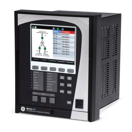
Page 80: Single Line Diagram
Setpoints > Device > Front Panel > Display Properties > Color Scheme Single Line Diagram for 845 and Breaker/Transformer status color The 845 has a single line diagram (SLD) that represents the power system. The single line diagram provided is pre-configured to show: •... - Page 81 Metering\ CT Bank 2 -K1\ K1 Ic W3 Ia Metering\ CT Bank 3 -K2\ K2 Ia W3 Ib Metering\ CT Bank 3 -K2\ K2 Ib W3 Ic Metering\ CT Bank 3 -K2\ K2 Ic 845 TRANSFORMER PROTECTION SYSTEM – INSTRUCTION MANUAL 3–7...
-
Page 82: Rugged And Membrane Front Panel Leds
• Reset mode: self-reset or latched The 845 front panel provides two columns of 7 LED indicators each, and 3 LED pushbutton indicators. The “IN-SERVICE” (LED 1) and the “PICKUP” (LED 4) indicators from the first LED column are non-programmable LEDs. The bottom 3 LED indicators from the first column, and the 7 LED indicators from the second LED column are fully programmable. - Page 83 CHAPTER 3: INTERFACES FRONT CONTROL PANEL INTERFACE Figure 3-10: LEDs for 845 relay protecting 3W Xfmr Some status indicators are common while some are feature specific which depend on the availability in the order code. The common status indicators in the first column are described below.
-
Page 84: Home Screen Icons
RESET button on the front panel is pressed after the operand is reset. Default labels are shipped in the package of every 845, together with custom templates. A custom LED template is available for editing and printing, refer to publication GET-20035 from http://www.gegridsolutions.com/multilin. -
Page 85: Relay Messages
PB action. The PB Target Message is displayed for 10 seconds then defaults to the screen that was displayed before pressing the pushbutton. The PB Target Message is recorded in the list with other generated Target Messages. 845 TRANSFORMER PROTECTION SYSTEM – INSTRUCTION MANUAL 3–11... -
Page 86: Self-Test Errors
The Critical Failure Relay (Output Relay 8) is energized when the relay is in-service, and no NOTE: major error is present Under both conditions, the targets cannot be cleared if the error is still active. Figure 3-12: Minor Errors 3–12 845 TRANSFORMER PROTECTION SYSTEM – INSTRUCTION MANUAL... - Page 87 CPU and LEDs, Keypad or peripheral memory devices Invalid MAC MAC address is not in Every 1 second Address the product range Calibration Error Unit has default Boot-up and Every 1 calibration values second 845 TRANSFORMER PROTECTION SYSTEM – INSTRUCTION MANUAL 3–13...
- Page 88 1. – Failure is logged after the detection of 5 consecutive failures 2. $ – is the slot ID (i.e., F, G, H etc.) 3–14 845 TRANSFORMER PROTECTION SYSTEM – INSTRUCTION MANUAL...
-
Page 89: Out Of Service
The factory default flash message time is 2 seconds. Label Removal The following procedure describes how to use the label removal tool. Bend the tabs of the tool upwards as shown in the image. 845 TRANSFORMER PROTECTION SYSTEM – INSTRUCTION MANUAL 3–15... - Page 90 Slide the label tool under the user-programmable pushbutton label as shown in the next image. Make sure the bent tab is pointing away from the relay. Remove the tool and user-programmable pushbutton label as shown in image. 3–16 845 TRANSFORMER PROTECTION SYSTEM – INSTRUCTION MANUAL...
-
Page 91: Software Interface
The EnerVista 8 Series Setup software can run without a 845 connected to the computer. In this case, settings may be saved to a file for future use. If a 845 is connected to a PC and communications are enabled, the 845 can be programmed from the setting screens. In addition, measured values, status and trip messages can be displayed with the actual value screens. -
Page 92: Installing The Enervista 8 Series Setup Software
In the EnerVista Launchpad window, click the Add Product button and select the 845 Protection System as shown below. Select the Web option to ensure the most recent software release, or select CD if you do not have a web connection, then click the Add Now button to list software items for the 845. - Page 93 If you are going to communicate from your computer to the 845 Relay using the USB port: 10. Plug the USB cable into the USB port on the 845 Relay then into the USB port on your computer. 11. Launch EnerVista 8 Series Setup software from LaunchPad.
-
Page 94: Upgrading The Software
The latest EnerVista software and firmware can be downloaded from: Software https://www.gegridsolutions.com/ After upgrading, check the version number under Help > About. If the new version does not display, try uninstalling the software and reinstalling the new versions. 3–20 845 TRANSFORMER PROTECTION SYSTEM – INSTRUCTION MANUAL... -
Page 95: Connecting Enervista 8 Series Setup Software To The Relay
USB is selected in the interface drop-down list. Select “USB” and press the Connect button. Ethernet or WiFi can also be used as the interface for Quick Connect as shown next. 845 TRANSFORMER PROTECTION SYSTEM – INSTRUCTION MANUAL 3–21... -
Page 96: Configuring Ethernet Communications
FASTPATH: Install and start the latest version of the EnerVista 8 Series Setup software (available from the GE EnerVista CD or Website). See the previous section for the installation procedure. Click on the Device Setup button to open the Device Setup window and click the Add Site button to define a new site. -
Page 97: Connecting To The Relay
Enter the IP address, slave address, and Modbus port values assigned to the 845 relay (from the Setpoints > Device > Communications menu). Click the Read Order Code button to connect to the 845 and upload the order code. If a communications error occurs, ensure that the Ethernet communication values correspond to the relay setting values. -
Page 98: Working With Setpoints & Setpoints Files
File to Device" and 2) saving Logic Designer changes online. Individual setting changes from the device front panel or Enervista 8 Series Setup software Online Window do not change the DEVICE IN SERVICE state. 3–24 845 TRANSFORMER PROTECTION SYSTEM – INSTRUCTION MANUAL... -
Page 99: Engaging A Device
Click = to exit from the keypad and keep the new value. Click on X to exit from the keypad and retain the old value. 845 TRANSFORMER PROTECTION SYSTEM – INSTRUCTION MANUAL 3–25... -
Page 100: File Support
In the Setpoints > System Setup > Voltage Sensing dialog box, click on Save to save the values into the 845. Click YES to accept any changes and exit the window. Click Restore to retain previous values. Click Default to restore Default values. -
Page 101: Downloading & Saving Setpoints Files
CHAPTER 3: INTERFACES SOFTWARE INTERFACE The 845 displays relay setpoints with the same hierarchy as the front panel display. Downloading & Saving Back up a copy of the in-service settings for each commissioned unit, so as to revert to the... -
Page 102: Creating A New Setpoints File
Select the file name and path to store the file, or select any displayed file name to replace an existing file. All 845 setpoint files should have the extension ‘.cid’ (for example, ‘845 1.cid’). Click OK to complete the process. Once this step is completed, the new file, with a complete path, is added to the 845 software environment. -
Page 103: Upgrading Setpoints Files To A New Revision
Upgrading Setpoints It is often necessary to upgrade the revision for a previously saved setpoint file after the Files to a New 845 firmware has been upgraded. This is illustrated in the following procedure: Revision Establish communications with the 845 relay. -
Page 104: Printing Setpoints
Setpoint lists can be printed in the same manner by right clicking on the desired file (in the file list) or device (in the device list) and selecting the Print Device Information or Print Settings File options. 3–30 845 TRANSFORMER PROTECTION SYSTEM – INSTRUCTION MANUAL... -
Page 105: Printing Values From A Connected Device
The following procedure illustrates how to load setpoints from a file. Before loading a setpoints file, it must first be added to the 845 environment as described in the section, Adding Setpoints Files to the Environment. -
Page 106: Uninstalling Files And Clearing Data
The Quick Setup item is accessed from the EnerVista software from different screens. Online and offline settings changes are made from the corresponding Quick Setup screen. Figure 3-14: 845 Quick Setup (Online) tree position 3–32 845 TRANSFORMER PROTECTION SYSTEM – INSTRUCTION MANUAL... - Page 107 CHAPTER 3: INTERFACES SOFTWARE INTERFACE Figure 3-15: 845 Quick Setup (Offline) tree position Quick Setup is designed to allow quick and easy user programming. Power system parameters, and settings for some simple overcurrent elements are easily set. The Quick Setup screen is shown as follows: Figure 3-16: Quick Setup window •...
-
Page 108: Upgrading Relay Firmware
Note that uploading firmware to a relay having a Communications card must be done with “Port 4 operation” configured as independent. Before upgrading firmware, it is very important to save the current 845 settings to a file on FASTPATH: your PC. After the firmware has been upgraded, it will be necessary to load this file back into the 845. -
Page 109: Loading New Relay Firmware
The firmware filename has the following format. The following screen appears. Select YES to proceed. EnerVista 8 Series Setup software now prepares the 845 to receive the new firmware file. The 845 front panel momentarily displays “Upload Mode”, indicating that it is in upload mode. - Page 110 SOFTWARE INTERFACE CHAPTER 3: INTERFACES The following screen appears, click YES to proceed with the firmware loading process. 3–36 845 TRANSFORMER PROTECTION SYSTEM – INSTRUCTION MANUAL...
- Page 111 Wait for the Comms upload process to complete. Wait for the Mains upload process to complete. The EnerVista 8 Series Setup software notifies the user when the 845 has finished loading and notifies the user to Cycle power to the relay to complete firmware update.
-
Page 112: Advanced Enervista 8 Series Setup Software Features
GE symbols (similar to ANSI). The following figure shows the objects that are available for design in the SLD Configurator and their maximum usage limits [X]. The maximum limit reflects the maximum possible order code. 3–38 845 TRANSFORMER PROTECTION SYSTEM – INSTRUCTION MANUAL... - Page 113 The control objects consist of selectable breakers and disconnect switches. The following figure shows the different symbols in the GE Standard style and IEC style. If the switching element is tagged, blocked, or bypassed, indicators with the letters “T”, “B”, and “By”...
- Page 114 0 degrees. Orientation in multiple directions allows the user to configure the single line diagram according to the existing drawings and ensure the correct side for the fixed/moving contacts. 3–40 845 TRANSFORMER PROTECTION SYSTEM – INSTRUCTION MANUAL...
- Page 115 Blocked” signal in both On and Off state. Figure 3-21: Reclose Blocked signal In addition, Remote Breaker status objects are added for GE and IEC style. Remote breaker status allows monitoring of three distant breakers. These objects are not controllable and hence cannot be used for selection and operation.
- Page 116 On the rugged front panel, the up and down keys can be pressed for navigation and on the membrane front panel, up, down, left, and right keys can be pressed. With the rugged front panel navigation, pressing down sequentially rotates through all the available breakers 3–42 845 TRANSFORMER PROTECTION SYSTEM – INSTRUCTION MANUAL...
- Page 117 ), the browsing highlight around the object disappears. If an object is Message Timeout selected, Home button operation will be prohibited. The object must be de-selected by pressing escape in order for the home button to function. 845 TRANSFORMER PROTECTION SYSTEM – INSTRUCTION MANUAL 3–43...
- Page 118 Tagged by operator. No operation allowed. Open or Closed T B By Tagged by operator. No operation allowed. For detailed tagging, blocking and bypassing operations, refer to the section Local Control Mode (breakers and switches). 3–44 845 TRANSFORMER PROTECTION SYSTEM – INSTRUCTION MANUAL...
-
Page 119: Flexcurve Editor
The user can load Trip Times from a CSV File • The screen above shows the model followed by 845 for viewing FlexCurves. Select Initialize to copy the trip times from the selected curve to the FlexCurve. 845 TRANSFORMER PROTECTION SYSTEM – INSTRUCTION MANUAL... -
Page 120: Transient Recorder (Waveform Capture)
"CFG." The other file is a "DAT" file, required by the COMTRADE file for proper display of waveforms. • To view a previously saved COMTRADE file, click the Open button and select the corresponding COMTRADE file. 3–46 845 TRANSFORMER PROTECTION SYSTEM – INSTRUCTION MANUAL... - Page 121 • From the window main menu bar, press the Preference button to open the COMTRADE Setup page, in order to change the graph attributes. 845 TRANSFORMER PROTECTION SYSTEM – INSTRUCTION MANUAL 3–47...
- Page 122 The Waveform Capture window reappears based on the selected graph attributes. To view a vector graph of the quantities contained in the waveform capture, press the View Phasors button to display the following window: 3–48 845 TRANSFORMER PROTECTION SYSTEM – INSTRUCTION MANUAL...
- Page 123 CHAPTER 3: INTERFACES SOFTWARE INTERFACE 845 TRANSFORMER PROTECTION SYSTEM – INSTRUCTION MANUAL 3–49...
-
Page 124: Protection Summary
With the software running and communications established, select the Setpoints > Protection Summary menu item to open the Protection Summary window. The Protection Summary screen is as follows: 3–50 845 TRANSFORMER PROTECTION SYSTEM – INSTRUCTION MANUAL... -
Page 125: Offline Settings File Conversion
The EnerVista 8 Series Setup software reduces the manual effort required when moving from an older product to the 845. The feature takes an existing settings file provided by the user and generates a new settings file compatible with the 8 Series order code specified by the user. - Page 126 If the file version is less than 5.0 it must be converted to 5.2 using the latest 745 EnerVista Setup before doing the 845 conversion. Click OK to begin the conversion and complete the process. Once this step is completed, the new file, with a complete path, is added to the EnerVista 8 Series Setup software environment.
-
Page 127: Conversion Summary Report
EnerVista taskbar or it can be printed from the “GUI” print button. Although the report shows successful conversion (green checkbox), the settings must still NOTE: be verified before putting the relay in service. 845 TRANSFORMER PROTECTION SYSTEM – INSTRUCTION MANUAL 3–53... - Page 128 SOFTWARE INTERFACE CHAPTER 3: INTERFACES 3–54 845 TRANSFORMER PROTECTION SYSTEM – INSTRUCTION MANUAL...
- Page 129 Setpoints Setpoints Main Menu The 845 has a considerable number of programmable setpoints, all of which make the relay extremely flexible. These setpoints have been grouped into a variety of menus which are available from the paths shown below. Each setpoints menu has sub-sections that describe in detail the setpoints found on that menu.
-
Page 130: Setpoints Setpoints Main Menu
Figure 4-2: Main Setpoints Screen Protection and Trip Breaker Selection Depending on order code, the 845 relay provides protection for either two-winding, or three-winding transformers. Based on this, either two or three breakers can be configured for status monitoring, tripping and closing. Each breaker menu provides a selection of trip output and/or close output relay. - Page 131 From the Relay HMI: Protection Element Menu • From the 845 PC program: Element’s Menu or Protection Summary From the Relay HMI: Protection Element Menu If Trip is selected as a “Function” for an element, and upon operation of that element, the LED “TRIP”...
- Page 132 IOC1 menu to be programmable. From 845 PC Program: Element Menu or Protection Summary Using the 845 PC program, there are two places where the menu of each protection, control, or monitoring element can be accessed: The element’s individual menu, and the Protection Summary menu.
- Page 133 When Alarm, Latched Alarm or Configurable is selected as a Function, the Output Relays 1 and 2, which have been assigned to trip Breaker 1 and 2 respectively, are de- activated for operation. 845 TRANSFORMER PROTECTION SYSTEM – INSTRUCTION MANUAL 4–5...
- Page 134 (non-selectable), if the function of an element is set to Alarm, Latched Alarm, or Configurable. In all other cases, the check boxes corresponding to those output relays will be active, and available for selection. 4–6 845 TRANSFORMER PROTECTION SYSTEM – INSTRUCTION MANUAL...
-
Page 135: Setpoints Entry Methods
Files can be stored and downloaded for fast, error free entry when a computer is used. To facilitate this process, the GE EnerVista CD with the EnerVista 8 Series Setup software is supplied with the relay. The relay leaves the factory with setpoints programmed to default values, and it is these values that are shown in all the setpoint message illustrations. - Page 136 845 relay. The targets disappear from the screen when “Self-Reset” is selected, and the conditions are cleared. The targets stay on the screen, when “Latched” is selected, and the conditions are cleared.
-
Page 137: Logic Diagrams
Each feature produces output flags (operands) which can be used further for creating logic in the FlexLogic equation editor, or Trip Bus, or can be directly assigned to trigger an output. The operands from all relay features constitute the list of FlexLogic operands. 845 TRANSFORMER PROTECTION SYSTEM – INSTRUCTION MANUAL 4–9... -
Page 138: Setpoints Text Abbreviations
Hz: Hertz • MAX: maximum • MIN: minimum • SEC, s: seconds • UV: undervoltage • OV: overvoltage • VT: voltage transformer • Ctrl: control • Hr & hr: hour • O/L: overload 4–10 845 TRANSFORMER PROTECTION SYSTEM – INSTRUCTION MANUAL... -
Page 139: Device
(greyed out). • In Regular configuration mode, all function/features and setpoints of the device are editable and nothing is hidden or greyed out. 845 TRANSFORMER PROTECTION SYSTEM – INSTRUCTION MANUAL 4–11... - Page 140 Instantaneous Direction Disabled Direction Disabled Voltage Restraint Disabled Voltage Restraint Disabled Relays Do Not Operate Volt Lower Limit p.u. PTOC 1 Block Relays Do Not Operate Events Enabled Targets Self-Reset PTOC 1 4–12 845 TRANSFORMER PROTECTION SYSTEM – INSTRUCTION MANUAL...
-
Page 141: Real-Time Clock
PTP and IRIG-B can be swapped. If both PTP and IRIG-B are available to the 845, by default the 845 clock syncs to PTP over IRIG-B. If PTP is not available the 845 CPU syncs the internal clock to IRIG-B. -
Page 142: Clock
DST START WEEK Range: 1st, 2nd, 3rd, 4th, Last Default: Not Set DST START HOUR Range: 0 to 23 Default: 2 DST END MONTH Range: January to December (all months) Default: Not Set 4–14 845 TRANSFORMER PROTECTION SYSTEM – INSTRUCTION MANUAL... -
Page 143: Ptp Configuration
Ethernet switch it is connected to 845 TRANSFORMER PROTECTION SYSTEM – INSTRUCTION MANUAL 4–15... -
Page 144: Sntp Protocol
PTP time. If set to 2 and IRIG-B is available, the relay syncs its reference to IRIG-B time. SNTP Protocol Path: Setpoints > Device > Real Time Clock > SNTP 4–16 845 TRANSFORMER PROTECTION SYSTEM – INSTRUCTION MANUAL... -
Page 145: Security
If password complexity is enabled, a user account requires an alpha-numeric password that meets the following requirements: • Passwords cannot contain the user account name or parts of the user's full name that exceed two consecutive characters 845 TRANSFORMER PROTECTION SYSTEM – INSTRUCTION MANUAL 4–17... -
Page 146: Basic Security
- Non-alphabetic characters (for example, ~, !, @, #, $,%, &) PASSWORD RECOVERY PROCEDURE In the event of losing all passwords, the 845 can be reset to factory defaults by following the procedure below: The customer sends an email to the customer support department providing a valid serial number and using a recognizable corporate email account. - Page 147 If this setting is enabled and an alarm or trip occurs on the relay, the Reset button is not available to the Operator. Only the Administrator can reset the relay with their password. 845 TRANSFORMER PROTECTION SYSTEM – INSTRUCTION MANUAL 4–19...
-
Page 148: Cybersentry
Commands may be issued freely through protocols other than Modbus (e.g., DNP, IEC 104, FASTPATH: and, IEC 61850) without user authentication or encryption of data taking place, even if the relay has the advanced security feature enabled. 4–20 845 TRANSFORMER PROTECTION SYSTEM – INSTRUCTION MANUAL... - Page 149 If the user enters the wrong password, the “Authentication Failed!” message is displayed. – If the maximum failed authentications occur, the “Account Blocked!” message is displayed. – The Observer user role is the default choice and it does not require a password. 845 TRANSFORMER PROTECTION SYSTEM – INSTRUCTION MANUAL 4–21...
- Page 150 The Access timeout is the time of idleness before a logged in user is automatically logged out. This timeout setting applies to all users, independent of the communication channel (serial, Ethernet or direct access). 4–22 845 TRANSFORMER PROTECTION SYSTEM – INSTRUCTION MANUAL...
- Page 151 The two menu items: Change Administrator Password, and Change Operator Password are available only to Administrator, which is the only role that has permissions to change passwords for itself and the other local roles. 845 TRANSFORMER PROTECTION SYSTEM – INSTRUCTION MANUAL 4–23...
- Page 152 For this reason, if these settings have been modified, offline, they will not be written during the file write operation. 4–24 845 TRANSFORMER PROTECTION SYSTEM – INSTRUCTION MANUAL...
- Page 153 The following are settings that need to be configured through EnerVista, in order to set up communication with a Radius server on 845. For configuring the RADIUS server itself, consult the RADIUS documentation. An example is provided, see Communications Guide.
-
Page 154: Communications
Setpoints > Device > Communications > RS485 BAUD RATE Range: 9600, 19200, 38400, 57600, 115200 Default: 115200 PARITY Range: None, Odd, Even Default: None PORT PROTOCOL Range: Modbus, DNP 3.0, IEC 60870-5-103 Default: Modbus 4–26 845 TRANSFORMER PROTECTION SYSTEM – INSTRUCTION MANUAL... -
Page 155: Wifi
IP address and mask. WiFi GWY IP Address The setting specifies the address of the access point AP which the 8 Series device uses for communicating over WiFi. 845 TRANSFORMER PROTECTION SYSTEM – INSTRUCTION MANUAL 4–27... - Page 156 This event is recorded to indicate a network connect. WiFi Disconnected This event is recorded to indicate a network disconnect. If the relay is in service mode and the settings are default a minor error is triggered. NOTE: 4–28 845 TRANSFORMER PROTECTION SYSTEM – INSTRUCTION MANUAL...
- Page 157 EnerVista for initial configuration and commissioning. Once the relay is configured, change the 8-Series relay default WiFi SSID and Passphrase settings before the relay goes into service. Figure 4-11: Example of WiFi Deployment 845 TRANSFORMER PROTECTION SYSTEM – INSTRUCTION MANUAL 4–29...
-
Page 158: Ethernet Ports
Typical link distance: 4 km Network Settings Menu The following are the network settings menu of the 845 to accommodate the features of the 845 product. If the communications card is installed network port 1 is no longer available. When using more than one Ethernet port, configure each to belong to a different network or subnet using the IP addresses and mask, else communication becomes unpredictable when more than one port is configured to the same subnet. - Page 159 LAN’s. In this mode of operation both ports cannot be connected to the same LAN. The receiving devices (845 ) process the first frame received and discard the duplicate through a link redundancy entity (LRE) or similar service that operates below layer 2.
-
Page 160: Modbus Protocol
Range: 1 to 254 in steps of 1 Default: 254 For the RS485 ports each 845 must have a unique address from 1 to 254. Address 0 is the broadcast address to which all Modbus slave devices listen. Addresses do not have to be sequential, but no two devices can have the same address, otherwise conflicts resulting in errors occur. - Page 161 (“holding registers”). Holding registers are 16 bit (two byte) values transmitted high order byte first. As a result all 845 Setpoints are sent as two bytes. The maximum number of registers that can be read in one transmission is 125.
- Page 162 Password Characters 3 and 4 62254 F32E 0000 Password Characters 5 and 6 62255 F32F 0000 Password Characters 7 and 8 62256 F330 0000 Password Characters 9 and 10 62257 F331 0000 4–34 845 TRANSFORMER PROTECTION SYSTEM – INSTRUCTION MANUAL...
- Page 163 0002 0005 0060 Table 4-13: Function Format for “Clear Energy Use Data” command Slave # Function Data Starting Number of Byte count Data 1 Data 2 Address Setpoints 0080 0002 0005 0069 845 TRANSFORMER PROTECTION SYSTEM – INSTRUCTION MANUAL 4–35...
-
Page 164: Routing
RT1 (2,3,4,5,6) DESTINATION Range: Standard IPV4 network address format (0.0.0.1 to 223.255.255.254) Default: 127.0.0.1 This setting sets the destination IPv4 route. This setting is available only if the communications card is present. 4–36 845 TRANSFORMER PROTECTION SYSTEM – INSTRUCTION MANUAL... - Page 165 255.255.255.0 The route destination must not be a connected network. The route gateway must be on a connected network. This rule applies to the gateway address of the default route as well. 845 TRANSFORMER PROTECTION SYSTEM – INSTRUCTION MANUAL 4–37...
-
Page 166: Dnp Protocol
This gateway is the address of Router 2, which is “aware” of destination 10.1.3.0 and is able to route packets coming from the 8 Series device and destined to EnerVista. DNP Protocol Path: Setpoints > Device > Communications > DNP protocol 4–38 845 TRANSFORMER PROTECTION SYSTEM – INSTRUCTION MANUAL... - Page 167 Range: 0 to 65519 in steps of 1 Default: 65519 The DNP address sets the DNP slave address. This number identifies the 845 on a DNP communications link. Each DNP slave must be assigned a unique address. DNP Client Address 1 (2) Range: standard IP address Default: 0.0.0.0...
- Page 168 This setting specifies a time delay for the detection of dead network TCP connections. If there is no data traffic on a DNP TCP connection for greater than the time specified by this setting, the connection will be aborted by the 845. This frees up the connection to be re-used by a client.
-
Page 169: Dnp / Iec104 Point Lists
FACTOR setting is set to “/ 1000”, and the Phase A voltage is 72000 V, the Phase A voltage is sent on to the 845 as 72. The settings are useful when analog input values must be adjusted to fit within certain ranges in DNP masters. - Page 170 When a freeze function is performed on a Binary Counter point, the frozen value is available in the corresponding Frozen Counter point. 845 Digital Counter values are represented as 16 or 32-bit integers. The DNP 3.0 protocol defines counters to be unsigned integers.
-
Page 171: Iec 60870-5-104
The IEC 60870-5-104 communications protocol is supported on Ethernet ports 4 and 5 only. Setting changes become active after rebooting. In 845 both DNP and IEC104 protocol can work at the same time, but the user has to FASTPATH: consider that there is only one point map. So, the two protocols use the same data mapping, i.e., same point index and same point source. - Page 172 “Network - TCP”, the IEC104 protocol can be used over TCP/IP on channels 1 or 2. The IEC104 NETWORK CLIENT ADDRESS settings can force the 845 to respond to a maximum of two specific IEC104 masters which own the configured IP Addresses. The settings in this sub-menu are shown below.
-
Page 173: Iec 60870-5-103
Setup software. A rebooting MUST be done before any changes made take affect. The IEC 61850 Configurator The 845 supports the IEC 61850 protocol which is identified by order code option “2A” or “2E”. The IEC 61850 configurator is found in both the online and offline section of the EnerVista 8 Series Setup software for configuring the online 845 and offline 845 settings file respectively. - Page 174 Read Device Settings: The menu option reads all the settings from the relay by TFTP and creates an 845 file with extension *.CID. The created *.CID file consists of two sections. A private section where all non IEC 61850 settings are available, and a public section in which IEC 61850 related settings are implemented.
-
Page 175: Remote Modbus Device
(BSG3). The 27 analog and 27 digital operands that are available in the device are supported and are pre-configured in the default settings file. The data defined for BSG3 are described in the 8 Series Protection Relay Platform Communications guide. 845 TRANSFORMER PROTECTION SYSTEM – INSTRUCTION MANUAL 4–47... -
Page 176: Transient Recorder
Number of Records Sample Rate Analog Channels Length-Cycles 1127 1503 Path: Setpoints > Device > Transient Recorder 4–48 845 TRANSFORMER PROTECTION SYSTEM – INSTRUCTION MANUAL... - Page 177 Selecting the “On” setting enables triggering of the recorder when any of the protection elements configured as a “Trip” function operates, or the state of the operand assigned to operate the #1 Trip output relay changes to “high”. 845 TRANSFORMER PROTECTION SYSTEM – INSTRUCTION MANUAL 4–49...
-
Page 178: Data Logger
Data Logger buffer space can be monitored to produce an alarm when the logged data occupies 80% of the data logger storage space. Target message, and operand “Data Logger ALRM” is generated at this time. 4–50 845 TRANSFORMER PROTECTION SYSTEM – INSTRUCTION MANUAL... - Page 179 “Rate”. The mean (average) is calculated simply using the well known ratio between the sum of all the values and their number over the time interval. 845 TRANSFORMER PROTECTION SYSTEM – INSTRUCTION MANUAL 4–51...
- Page 180 DEVICE CHAPTER 4: SETPOINTS Figure 4-13: Data Logger Storage Capacity 4–52 845 TRANSFORMER PROTECTION SYSTEM – INSTRUCTION MANUAL...
-
Page 181: Fault Reports
Path: Setpoints > Device > Fault Report FUNCTION Range: Disabled, Enabled Default: Disabled 845 TRANSFORMER PROTECTION SYSTEM – INSTRUCTION MANUAL 4–53... -
Page 182: Event Data
Fourteen other status LEDs are available, 12 of which are programmable. Please refer to Front Control Panel Interface. The USB port on the Front Panel, is intended for connection to a portable PC. FASTPATH: 4–54 845 TRANSFORMER PROTECTION SYSTEM – INSTRUCTION MANUAL... -
Page 183: Programmable Leds
LED 3: ALARM - see the default setpoint above and the description • LED 4: PICKUP – non-programmable. The LED is hardcoded to show a green light when at least one element has picked up. 845 TRANSFORMER PROTECTION SYSTEM – INSTRUCTION MANUAL 4–55... -
Page 184: Programmable Pushbuttons
Pushbutton states can be logged by the Event Recorder and displayed as Target Messages. In latched mode, user-defined messages can also be associated with each pushbutton and displayed when the pushbutton is ON or changing to OFF. 4–56 845 TRANSFORMER PROTECTION SYSTEM – INSTRUCTION MANUAL... - Page 185 The PUSHBTN 1 OFF TEXT setting is linked to PUSHBUTTON 1 OFF operand and will be displayed in conjunction with PUSHBTN 1 ID only if the pushbutton element is in “Latched” mode. 845 TRANSFORMER PROTECTION SYSTEM – INSTRUCTION MANUAL 4–57...
- Page 186 “active” status after the pushbutton has been released. The length of time the operand remains on has no effect on the pulse duration. The setting is required to set the duration of the pushbutton operating pulse. EVENTS Range: Disabled, Enabled Default: Enabled 4–58 845 TRANSFORMER PROTECTION SYSTEM – INSTRUCTION MANUAL...
- Page 187 CHAPTER 4: SETPOINTS DEVICE Figure 4-15: Pushbuttons Logic Diagram 845 TRANSFORMER PROTECTION SYSTEM – INSTRUCTION MANUAL 4–59...
-
Page 188: Tab Pushbuttons
This setting specifies the 13-character line of the user-programmable message and is intended to provide the ID information of the pushbutton. This text is used to describe the pushbutton in the FlexLogic operands. 4–60 845 TRANSFORMER PROTECTION SYSTEM – INSTRUCTION MANUAL... - Page 189 This setting specifies the time required for a pushbutton to be pressed before it is deemed active. The timer is Reset upon release of the pushbutton. Note that any pushbutton operation will require the pushbutton to be pressed a minimum of 100ms. 845 TRANSFORMER PROTECTION SYSTEM – INSTRUCTION MANUAL 4–61...
- Page 190 “active” status after the pushbutton has been released. The length of time the operand remains on has no effect on the pulse duration. The setting is required to set the duration of the pushbutton operating pulse. EVENTS Range: Disabled, Enabled Default: Enabled 4–62 845 TRANSFORMER PROTECTION SYSTEM – INSTRUCTION MANUAL...
-
Page 191: Annunciator
This setting when enabled, automatically navigates to the annunciator panel page from where the indication was triggered. While in the annunciator panel, if no action is taken, the screen returns back to the home page after the timeout setting. 845 TRANSFORMER PROTECTION SYSTEM – INSTRUCTION MANUAL 4–63... - Page 192 Enter key again acknowledges the alarm and pressing the Escape button discards the message. When the alarms are active under latched mode, a power loss retains the previous state of the alarm as the alarm states are stored in non-volatile memory. 4–64 845 TRANSFORMER PROTECTION SYSTEM – INSTRUCTION MANUAL...
-
Page 193: Display Properties
The target message interrupts the message timeout, overriding it. The message timeout starts timing after each target message, and if no more activity is recorded for the specified time, the display goes back to the default screen. 845 TRANSFORMER PROTECTION SYSTEM – INSTRUCTION MANUAL 4–65... -
Page 194: Default Screens
Range: varieties of screens for selection Default: SLD (for Default Screen 1 only), Off (for Default Screen 2/3 only) The setpoint enables the user to input up to 3 default screens from a list of screens. 4–66 845 TRANSFORMER PROTECTION SYSTEM – INSTRUCTION MANUAL... -
Page 195: Home Screens
Default: Tab PB Summary HOME SCREEN 3 Range: All available pages Default: Annunciator Pg 1 HOME SCREEN 4 Range: All available pages Default: Values HOME SCREEN 5 to 10 Range: All available pages Default: Off 845 TRANSFORMER PROTECTION SYSTEM – INSTRUCTION MANUAL 4–67... -
Page 196: Resetting
When the relay is commissioned and the Validate CANBUS IO command is set to Yes the current auto detect value is saved to non-volatile memory. This value is then used to configure all display dependencies and used in self-test validation. 4–68 845 TRANSFORMER PROTECTION SYSTEM – INSTRUCTION MANUAL... - Page 197 Lower the Voltage Cutoff and Current Cutoff levels with care as the relay accepts lower FASTPATH: signals as valid measurements. Unless dictated otherwise by a specific application, the default settings of “0.020 pu” for current and “1.0 V” for voltage are recommended.” 845 TRANSFORMER PROTECTION SYSTEM – INSTRUCTION MANUAL 4–69...
-
Page 198: System
• Breakers: information related to detecting the status of breakers by assigning contact inputs • FlexCurves: information related to inverse time curves with user-programmable points 4–70 845 TRANSFORMER PROTECTION SYSTEM – INSTRUCTION MANUAL... -
Page 199: Current Sensing
The Voltage Sensing menu provides the setup for all VTs (PTs) connected to the relay voltage terminals. The 845 can be connected to 4 VTs, i. e. three-phase VTs from either a Wye (Star) or a Delta connection, and one auxiliary VT. The VT inputs setup for the 845 is shown below: Path: Setpoints >... - Page 200 115/√3 = 66.4 V. On a 14.4 kV system with a Delta connection and a VT primary to secondary turns ratio of 14400:120, the voltage value entered would be 120 V, i.e. 14400/120. 4–72 845 TRANSFORMER PROTECTION SYSTEM – INSTRUCTION MANUAL...
-
Page 201: Power Sensing
SYSTEM Power Sensing The power computation in the 845 relay is performed using the voltage and current inputs from the card inserted in slot J. In cases when the connected VTs and CTs have opposite polarity, the power sensing menu provides for inverting the power measurement. -
Page 202: Transformer
(no PTs, or voltage reads zero), the source for frequency tracking is the CT bank from the same card, as the voltage bank. For 845 relay orders without VT inputs, the source for frequency tracking is K1 - the first CT bank from the card residing in K-slot. -
Page 203: Transformer Setup
This setting defines the winding temperature rise over 30°C ambient temperature. The setting is automatically selected for the transformer type as shown in the following figure. The data reflects the data outlined in ANSI/IEEE 57.91, ANSI/IEEE 57.92, and ANSI/ IEEE 57.94 standards. 845 TRANSFORMER PROTECTION SYSTEM – INSTRUCTION MANUAL 4–75... - Page 204 “Sealed Self Cooled”, “Vented Self Cooled”, “Forced Cooled”: as named TOP OIL RISE OVER AMBIENT Range: 1 to 200°C in steps of 1 Default: 35°C This setting is available from the transformer nameplate data. 4–76 845 TRANSFORMER PROTECTION SYSTEM – INSTRUCTION MANUAL...
- Page 205 CT on the winding side where energization happens on the transformer and compute/pick various parameters during an energization event. Voltage bank J2 will be taken into consideration for generating voltage waveform based on the 845 order code. YEAR OF MANUFACTURE...
- Page 206 Path: Setpoints > System > Transformer > Winding 2(3) All transformer windings from 845 are associated with CT bank inputs. Depending on the selected 845 order code, the following CT banks represent the winding currents: 845 orders for two-winding transformers without voltage inputs: –...
- Page 207 I-II-III is connected to transformer windings labeled I, II and III respectively. Magnitude Compensation The percent differential protection from the 845 relay uses the phase-phase voltage and the CT primary setting for Winding 1 as a reference, to perform magnitude compensation for (bring to common base) the currents measured from the other windings: Winding 2 and Winding 3.
- Page 208 To compute differential and restraint currents, the 845 relay uses Winding 1 phase-phase voltage and the primary CT rating from the Signal input used for Winding 1. The 845 relay computes magnitude compensation factors for Winding 2 and Winding 3 currents as...
- Page 209 CT ratio mismatch) is 20. Phase Shift Compensation Phase Compensation Reference: The percent differential protection from the 845 relay uses either the Delta, or the Zig-Zag winding (depending on the transformer setup) as a reference to perform phase shift compensation. If the transformer has only “Wye”...
- Page 210 Users with a system phase sequence of ACB must determine the transformer type for this sequence. The following diagram shows the internal connections of the Y/d30 transformer from our example. 4–82 845 TRANSFORMER PROTECTION SYSTEM – INSTRUCTION MANUAL...
- Page 211 (winding 1) in a delta. This compensates for the phase angle lag introduced in the delta side (winding 2). The 845 performs the phase angle correction internally based on the setpoint “Angle With Respect to W1” from the menu System > Transformer > Transformer Setup > see “Winding 2”, and the same setpoint from the menu System >...
- Page 212 The phase compensation angle φ is the angle by which a winding current is shifted comp with reference to the angle of the reference winding, and is calculated by the 845 for each winding as follows φ [w] = | φ[w ] –...
- Page 213 ------ - I ------ - I -- - I -- - I -- - I -- - I -- - I -- - I -- - I -- - I -- - I 845 TRANSFORMER PROTECTION SYSTEM – INSTRUCTION MANUAL 4–85...
- Page 214 M[w3] - magnitude compensation factor for winding 3 (see previous sections) [w] , I [w], and I [w]- phase and zero sequence compensated winding phase currents (see earlier) The magnitude compensation factor for the reference winding is 1. 4–86 845 TRANSFORMER PROTECTION SYSTEM – INSTRUCTION MANUAL...
- Page 215 1 , are scaled only to be presented in times Winding 1 CT. = 1 , - magnitude compensation factor for winding 1 - REFERENCE Winding 1 currents = (M ))/CT = 104.5/500 = 0.209 x CT load 845 TRANSFORMER PROTECTION SYSTEM – INSTRUCTION MANUAL 4–87...
- Page 216 The differential and restraint currents would be as follows: Differential currents: = 0 x CT = 0 x CT = 0 x CT Restraint currents: = 0.209 x CT = 0.209 x CT = 0.209 x CT 4–88 845 TRANSFORMER PROTECTION SYSTEM – INSTRUCTION MANUAL...
- Page 217 Transformer Types and Phase Shift compensation angles The figures below show standard two-winding and three-winding transformer types, and the phase compensation angles which reference the phase reference winding used by the relay. 845 TRANSFORMER PROTECTION SYSTEM – INSTRUCTION MANUAL 4–89...
- Page 218 SYSTEM CHAPTER 4: SETPOINTS Figure 4-26: Two-winding transformer connections 4–90 845 TRANSFORMER PROTECTION SYSTEM – INSTRUCTION MANUAL...
- Page 219 CHAPTER 4: SETPOINTS SYSTEM 845 TRANSFORMER PROTECTION SYSTEM – INSTRUCTION MANUAL 4–91...
- Page 220 SYSTEM CHAPTER 4: SETPOINTS Figure 4-27: Three-winding transformer connections 4–92 845 TRANSFORMER PROTECTION SYSTEM – INSTRUCTION MANUAL...
- Page 221 CHAPTER 4: SETPOINTS SYSTEM 845 TRANSFORMER PROTECTION SYSTEM – INSTRUCTION MANUAL 4–93...
- Page 222 SYSTEM CHAPTER 4: SETPOINTS 4–94 845 TRANSFORMER PROTECTION SYSTEM – INSTRUCTION MANUAL...
- Page 223 CHAPTER 4: SETPOINTS SYSTEM 845 TRANSFORMER PROTECTION SYSTEM – INSTRUCTION MANUAL 4–95...
- Page 224 SYSTEM CHAPTER 4: SETPOINTS 4–96 845 TRANSFORMER PROTECTION SYSTEM – INSTRUCTION MANUAL...
- Page 225 CHAPTER 4: SETPOINTS SYSTEM 845 TRANSFORMER PROTECTION SYSTEM – INSTRUCTION MANUAL 4–97...
- Page 226 SYSTEM CHAPTER 4: SETPOINTS 4–98 845 TRANSFORMER PROTECTION SYSTEM – INSTRUCTION MANUAL...
- Page 227 CHAPTER 4: SETPOINTS SYSTEM 845 TRANSFORMER PROTECTION SYSTEM – INSTRUCTION MANUAL 4–99...
-
Page 228: Xfmer Status Detection
SYSTEM CHAPTER 4: SETPOINTS Xfmer Status The 845 relay can be set to detect the status of the protected transformer when energized Detection or de-energized. The detection of the transformer energized/de-energized status is set to produce operands, which can be used for transformer monitoring applications, and to trigger an LED (operand set by the factory to trigger LED “Transformer De-Energized”). - Page 229 CHAPTER 4: SETPOINTS SYSTEM Figure 4-28: Transformer Status Detection Logic Diagram 845 TRANSFORMER PROTECTION SYSTEM – INSTRUCTION MANUAL 4–101...
- Page 230 The 845 relay calculates delta voltages, and compares them against the specified FASTPATH: minimum voltage threshold given in times VT. If Wye is programmed for phase VT connection, the VT unit is obtained by multiplying the programmed secondary voltage through the VT ratio and SQRT(3).
-
Page 231: Thermal Inputs
Thermal Inputs The 845 relay can be set to monitor the hottest-spot winding temperature, the aging acceleration factor and the transformer insulation life. In order for the relay to perform the correct calculations, the user needs to enter transformer data and program RTD inputs for measuring ambient and top-oil temperatures. -
Page 232: On-Load Tap Changer
CHAPTER 4: SETPOINTS On-load Tap Changer This section contains the settings to configure the tap position input. The 845 relay offers tap position detection by monitoring either a resistive input from the tap changer control circuitry, a dcmA analog input, or by Binary Coded Decimal (BCD) inputs. Based on the detected tap, the 845 relay dynamically corrects for CT ratio mismatch resulting from the changes of the voltage ratio of the transformer. - Page 233 All transformer windings from 845 are associated with CT bank inputs. Depending on 845 ordering, the following CT banks represent the winding currents: 845 orders for two-winding transformers without voltage inputs: –...
- Page 234 MIN TAP Range: -19 to +35 in steps of 1 Default: -16 This setting defines the minimum tap from the tap changer. The 845 uses the setting to signal when the minimum tap is reached. NEUTRAL TAP Range: -17 to +37 in steps of 1 Default: 0 This setting defines the neutral tap position.
- Page 235 IO_A card for up to 19 taps. The selection of the suitable setting depends on the customer’s criteria. In both cases, when the BCD format is chosen, the neutral tap position must be entered. 845 TRANSFORMER PROTECTION SYSTEM – INSTRUCTION MANUAL 4–107...
- Page 236 BCD bit 6 BCD bit 5 BCD bit 4 BCD bit 3 BCD bit 2 BCD bit 1 Input Input Input Input Input Input Position +Tap +Tap +Tap +Tap +Tap +Tap +Tap 4–108 845 TRANSFORMER PROTECTION SYSTEM – INSTRUCTION MANUAL...
- Page 237 Position +Tap +Tap +Tap +Tap +Tap +Tap +Tap +Tap +Tap +Tap +Tap invalid +Tap invalid +Tap invalid +Tap invalid +Tap invalid +Tap Invalid …. …. … … … … … … -Tap 845 TRANSFORMER PROTECTION SYSTEM – INSTRUCTION MANUAL 4–109...
-
Page 238: Breakers
-Tap Breakers The status of each winding breaker is detected on the 845 relay by monitoring the state/ states of either one, or preferably two contact inputs. It is highly recommended to monitor the status of the breaker using both breaker auxiliary contacts 52a, and 52b. However using only one of them is also acceptable. - Page 239 PB LED: BREAKER OPENED FLEXLOGIC OPERANDS FlexLogic operand (BKR 52a state) BKR 1 Opened FlexLogic operand (BKR 52b status) LED: ALARM 30 ms FLEXLOGIC OPERANDS LATCH BKR 1 Unkwn State 892740A2.cdr RESET (command) 845 TRANSFORMER PROTECTION SYSTEM – INSTRUCTION MANUAL 4–111...
-
Page 240: Switches
Select an operand from the list of FlexLogic operands, which when asserted resets the Switch Discrepancy state. Please note that resetting the discrepancy alarm will work only after no discrepancy condition exists between the switch aux contacts 89a and 89b. 4–112 845 TRANSFORMER PROTECTION SYSTEM – INSTRUCTION MANUAL... - Page 241 89b contact open Not Configured Table 4-22: Switch status with both contacts 89a and 89b programmed 89a Contact Status 89b Contact Status Disconnect Switch Status SW[X] Opened SW[X] Closed SW[X] Intermittent, SW[X] Discrepancy 845 TRANSFORMER PROTECTION SYSTEM – INSTRUCTION MANUAL 4–113...
- Page 242 SYSTEM CHAPTER 4: SETPOINTS Figure 4-33: Disconnect Switch State Detection logic diagram 4–114 845 TRANSFORMER PROTECTION SYSTEM – INSTRUCTION MANUAL...
-
Page 243: Flexcurves
The following table details the 120 points as well as the characteristic for each of them, and a blank cell where the user can write the time value when the operation (for I > I pickup or the reset (for I < I ) is required. pickup 845 TRANSFORMER PROTECTION SYSTEM – INSTRUCTION MANUAL 4–115... - Page 244 FlexCurves are customized by editing the operating time (ms) values at pre-defined per- unit current multiples. Note that the pickup multiples start at zero (implying the "reset time"), operating time below Pickup, and operating time above Pickup. 4–116 845 TRANSFORMER PROTECTION SYSTEM – INSTRUCTION MANUAL...
-
Page 245: Inputs
Figure 4-34: Inputs Display Hierarchy Contact Inputs The 845 relay is equipped with a number of Contact Inputs, depending on the Order Code, which can be used to provide a variety of functions such as for circuit breaker control, external trips, blocking of protection elements, etc. Contact inputs accept wet and dry input signals. - Page 246 LOW-HIGH (marks no.1 and 2 in the figure below) and HIGH-LOW (marks no. 3 and 4 below) transitions. Figure 4-35: Contact Input Debouncing Mechanism and Time-stamping Sample Timing 4–118 845 TRANSFORMER PROTECTION SYSTEM – INSTRUCTION MANUAL...
- Page 247 The value is selected according to the following criteria: 17 for 24 V sources, 33 for 48 V sources, 84 for 110 to 125 V sources and 166 for 250 V sources. For internal wetting set the Voltage Threshold to 17V. FASTPATH: 845 TRANSFORMER PROTECTION SYSTEM – INSTRUCTION MANUAL 4–119...
-
Page 248: Virtual Inputs
The 52b contact is closed when the breaker is open and open when the breaker is closed. FASTPATH: Virtual Inputs The 845 relay is equipped with 64 Virtual Inputs that can be individually programmed to respond to input signals from the keypad or from communications protocols. This has the following advantages over Contact Inputs only: •... - Page 249 FUNCTION : Disabled=0 Enabled =1 Virtual Input 1 to ON =1 LATCH FlexLogic Operands Reset- Virtual Input 1 to OFF =0 VI 1 ON Dominant SETPOINTS VIRTUAL INPUT 1 TYPE: Latched 892705A1.cdr Self-Reset 845 TRANSFORMER PROTECTION SYSTEM – INSTRUCTION MANUAL 4–121...
-
Page 250: Remote Inputs
13 characters. UNITS Range: Any combination of 6 Characters Default: units This setting allows the user to give a symbolic name to the engineering units. The length is limited to 6 characters. 4–122 845 TRANSFORMER PROTECTION SYSTEM – INSTRUCTION MANUAL... - Page 251 Range: 0 to 600 s in steps of 1 s Default: 2 This setpoint will operate if the trip pickup condition is maintained for a longer time than the delay time set here. 845 TRANSFORMER PROTECTION SYSTEM – INSTRUCTION MANUAL 4–123...
- Page 252 This setpoint selects a fixed time interval to delay dropping out the output signal after being generated. ALARM OUTPUT RELAY X For details see Common Setpoints. BLOCK Range: Any FlexLogic operand Default: Off 4–124 845 TRANSFORMER PROTECTION SYSTEM – INSTRUCTION MANUAL...
- Page 253 This setting enables or disables the events of the Analog Input function. TARGETS Range: Disabled, Self-Reset, Latched Default: Latched The selection of the Self-Reset or Latched setting enables the targets of the Analog Input function. 845 TRANSFORMER PROTECTION SYSTEM – INSTRUCTION MANUAL 4–125...
- Page 254 INPUTS CHAPTER 4: SETPOINTS Figure 4-37: Analog Input Threshold Logic Diagram 4–126 845 TRANSFORMER PROTECTION SYSTEM – INSTRUCTION MANUAL...
-
Page 255: Output Relays
The I/O module from slot F, for example, provides five output relays. The 845 auxiliary relays, starting with Aux. Relay 1, can be energized from the menu of each protection or control feature, or from their respective menus when assigning a FlexLogic operand (trigger) under the setpoint "Aux Rly # Operate". - Page 256 Switch, and vice versa. The table below defines the dependency of output relay availability based on the first come-first serve principal. 4–128 845 TRANSFORMER PROTECTION SYSTEM – INSTRUCTION MANUAL...
- Page 257 Relay Not Ready state, or detection of Major Self-Test error. MAINTAINING AN UNINTERRUPTED PROCESS The Output Relays are operational (can be closed/opened) while the 845 Transformer Protection System is In-Service. If the relay goes into “Out-of-Service” mode, the status of all previously energized output relays changes to de-energized.
-
Page 258: Auxiliary Relay Selected For Breaker Trip
(if not already activated by an operand driving this output relay) when control power is removed from the 845. Conversely a non-failsafe relay is de-energized in its normal non-activated state and will not change state when control power is removed from the 845 (if not already activated by a protection element). - Page 259 CHAPTER 4: SETPOINTS OUTPUTS Figure 4-40: Relay 1 “TRIP” logic diagram 845 TRANSFORMER PROTECTION SYSTEM – INSTRUCTION MANUAL 4–131...
-
Page 260: Aux Relay Selected For Breaker Close
The output relays selected under the Breaker menu for breaker closing are excluded from NOTE: the list of outputs for selection under the menus of all elements providing such output relay selection. 4–132 845 TRANSFORMER PROTECTION SYSTEM – INSTRUCTION MANUAL... - Page 261 CHAPTER 4: SETPOINTS OUTPUTS Figure 4-41: “Close” logic diagram 845 TRANSFORMER PROTECTION SYSTEM – INSTRUCTION MANUAL 4–133...
-
Page 262: Auxiliary Output Relays
FlexLogic operand (trigger) under the setpoint “Aux Rly # Operate”. Changing the state of any of the Auxiliary Relays will be inhibited if the 845 relay is in “Not Ready” mode. NAME... -
Page 263: Critical Failure Relay #8
Relay ( Ready = 1) Critical Failure Relay The 845 relay is equipped with one output relay (# 8 - “Critical Failure Relay”) for failsafe indication. The Critical Failure Relay is a Form-C contact with one NO and one NC contact (no control power). -
Page 264: Virtual Outputs
CHAPTER 4: SETPOINTS Virtual Outputs The 845 relay is equipped with 96 virtual outputs that may be assigned for use via FlexLogic. Virtual outputs not assigned for use are set to OFF (Logic 0). A name can be assigned to each virtual output. Any change of state to a virtual output can be logged as an event if programmed to do so. - Page 265 Each channel can be programmed to represent a FlexAnalog parameter available in the respective 8 Series relay. The range and steps is the same as the range of the FlexAnalog. 845 TRANSFORMER PROTECTION SYSTEM – INSTRUCTION MANUAL 4–137...
-
Page 266: Protection
PROTECTION CHAPTER 4: SETPOINTS Protection The 845 protection elements are organized in six (6) identical setpoint groups: Setpoint Group 1 to Setpoint Group 6. Figure 4-45: Protection Display Hierarchy Each Setpoint Group has the same protection functions, depending on the relay order code. - Page 267 Neutral Overvoltage Protection (59N) • Negative Sequence Overvoltage Protection (59_2) • Volts per Hertz (24) Power Elements • Directional Power (32) Frequency Elements • Underfrequency (81U) • Overfrequency (81O) • Frequency Rate of Change (81R) 845 TRANSFORMER PROTECTION SYSTEM – INSTRUCTION MANUAL 4–139...
-
Page 268: Percent Differential
CHAPTER 4: SETPOINTS Percent Differential The 845 relay provides one Overall Percent Differential element per setpoint group. The setpoints from the protection menu define a dual slope, dual breakpoint differential/ restraint characteristic. The filtering and calculation of transformer differential and restraint currents, and differential current 2nd and 5th harmonics are as shown in the figure: Filtering and calculation of differential and restraint currents. - Page 269 Eq. 2 max( comp comp comp Refer to the Transformer Setup chapter for the winding currents magnitude and phase NOTE: shift compensations performed by the 845 relay. Figure 4-47: Differential/Restraint Characteristic for main transformer Operate Block Slope 2 Slope 1 Pickup...
- Page 270 Winding 1 (138kV) CT – reference. Magnitude factor: M(w1) = 1 Winding 2(4.16kV) CT – non reference. Magnitude factor: M(w2) = 4.16 *3000/138*200 = 0.4521 Based on emergency MVA rating: Winding 1 rated current = 28MVA/(138kV*sqrt(3)) = 117 Amps 4–142 845 TRANSFORMER PROTECTION SYSTEM – INSTRUCTION MANUAL...
- Page 271 Break 2 must be set to the through-fault current which causes the worst CT to saturate, with saturation free time of at least half power cycle. To define the degree of CT saturation, the IEEE CT saturation tool can be used: 845 TRANSFORMER PROTECTION SYSTEM – INSTRUCTION MANUAL 4–143...
- Page 272 Break 2 must be set to a through fault current so that the CT (3000:5) produces at least ½ cycle saturation free time. The solution is to change the fault current to 15000 kA. The waveform now shows a bigger part of the first cycle before saturation. 4–144 845 TRANSFORMER PROTECTION SYSTEM – INSTRUCTION MANUAL...
- Page 273 0.4521, the Break 2 setting would be: Break 2 = 5 *0.4521 = 2.21 xCT (w1) Figure 4-48: Examples of differential/restraint trajectory during internal fault Figure 4-49: Examples of differential/restraint trajectory during external fault 845 TRANSFORMER PROTECTION SYSTEM – INSTRUCTION MANUAL 4–145...
- Page 274 This differential current is a result of the transformer magnetizing current, CT inaccuracies, and transformer ratio that would change by the transformer on-load tap changer. When the tap changer feature is set properly, the 845 compensates the transformation ratio which impacts the differential protection automatically.
- Page 275 0.04 x CT, the 2nd harmonic current from that phase is dropped (zeroed) from the equation for averaging, and the divider is decreased from 3 to 2. The same happens if the magnitude of the differential current on 845 TRANSFORMER PROTECTION SYSTEM – INSTRUCTION MANUAL 4–147...
- Page 276 Any, or all of the output relays can be selected to operate, upon percent differential operation. The 845 relay provides one instantaneous differential element per setpoint group. The Instantaneous differential protection is not biased protection and operates similar to the instantaneous overcurrent protection. Inputs to this protection are computed by the relay per-phase differential currents.
- Page 277 Percent Differential function is set to “Configurable”. EVENTS Range: Disabled, Enabled Default: Disabled TARGETS Range: Disabled, Self-Reset, Latched Default: Latched Figure 4-50: Percent and Instantaneous Differential Protection Logic Diagram 845 TRANSFORMER PROTECTION SYSTEM – INSTRUCTION MANUAL 4–149...
- Page 278 PROTECTION CHAPTER 4: SETPOINTS 4–150 845 TRANSFORMER PROTECTION SYSTEM – INSTRUCTION MANUAL...
-
Page 279: Transformer Overload
BLOCK Range: Off, Any FlexLogic operand Default: Off OUTPUT RELAYS Range: Do Not Operate, Operate Default: Do Not Operate EVENTS Range: Enabled, Disabled Default: Enabled TARGETS Range: Self-reset, Latched, Disabled Default: Latched 845 TRANSFORMER PROTECTION SYSTEM – INSTRUCTION MANUAL 4–151... - Page 280 PROTECTION CHAPTER 4: SETPOINTS Figure 4-51: Transformer Overload Logic Diagram 4–152 845 TRANSFORMER PROTECTION SYSTEM – INSTRUCTION MANUAL...
-
Page 281: Current Elements
IEEE Moderately ANSI Normally IEC Curve C (BS IAC Inverse FlexCurves™ A, B, Inverse Inverse 142) C and D ANSI Moderately IEC Short Inverse IAC Short Inverse Recloser Curve Inverse Definite Time 845 TRANSFORMER PROTECTION SYSTEM – INSTRUCTION MANUAL 4–153... - Page 282 1.626 136.090 57.130 21.880 12.010 7.780 5.564 4.255 3.416 2.845 2.439 181.454 76.174 29.174 16.014 10.374 7.419 5.674 4.555 3.794 3.252 10.0 226.817 95.217 36.467 20.017 12.967 9.274 7.092 5.693 4.742 4.065 4–154 845 TRANSFORMER PROTECTION SYSTEM – INSTRUCTION MANUAL...
- Page 283 Table 4-27: ANSI CURVE TRIP TIMES (IN SECONDS) MULTIPLIER CURRENT (I/Ipickup) (TDM) 10.0 ANSI EXTREMELY INVERSE 2.000 0.872 0.330 0.184 0.124 0.093 0.075 0.063 0.055 0.049 4.001 1.744 0.659 0.368 0.247 0.185 0.149 0.126 0.110 0.098 845 TRANSFORMER PROTECTION SYSTEM – INSTRUCTION MANUAL 4–155...
- Page 284 TDM = Multiplier setting I = input current = Pickup Current setting pickup K, E = constants = characteristic constant = reset time in seconds (assuming energy capacity is 100% and RESET is RESET “Timed”) 4–156 845 TRANSFORMER PROTECTION SYSTEM – INSTRUCTION MANUAL...
- Page 285 1.835 1.067 0.668 0.526 0.451 0.404 0.371 0.346 0.327 0.311 0.80 2.446 1.423 0.890 0.702 0.602 0.538 0.494 0.461 0.435 0.415 1.00 3.058 1.778 1.113 0.877 0.752 0.673 0.618 0.576 0.544 0.518 845 TRANSFORMER PROTECTION SYSTEM – INSTRUCTION MANUAL 4–157...
- Page 286 A to E = constants = characteristic constant = reset time in seconds (assuming energy capacity is 100% and RESET is RESET “Timed”) Table 4-30: GE TYPE IAC INVERSE TIME CURVE CONSTANTS IAC CURVE SHAPE IAC Extremely Inverse 0.0040 0.6379 0.6200 1.7872...
- Page 287 T CURVES The curves for the I t are derived from the formula: Where: T = operate time (in seconds) TDM = Multiplier setting I = input current = Pickup Current setting pickup 845 TRANSFORMER PROTECTION SYSTEM – INSTRUCTION MANUAL 4–159...
-
Page 288: Percent Of Load-To-Trip
It is the ratio of this current to the lowest pickup setting among the phase time and the instantaneous overcurrent elements. If all of these elements are disabled, the value displayed is “0”. 4–160 845 TRANSFORMER PROTECTION SYSTEM – INSTRUCTION MANUAL... -
Page 289: Phase Time Overcurrent Protection (51P)
CHAPTER 4: SETPOINTS PROTECTION Phase Time The 845 relay TOC element can be configured with any of the IEEE, ANSI, IEC, and IAC Overcurrent standard inverse curves, any of the four FlexCurves, or set to definite time. The selection of... - Page 290 Figure 4-53: Voltage Restraint characteristics for Phase TOC BLOCK Range: Off, Any FlexLogic operand Default: Off OUTPUT RELAY X For details see Common Setpoints. EVENTS Range: Enabled, Disabled Default: Enabled TARGETS Range: Self-reset, Latched, Disabled Default: Self-reset 4–162 845 TRANSFORMER PROTECTION SYSTEM – INSTRUCTION MANUAL...
- Page 291 CHAPTER 4: SETPOINTS PROTECTION Figure 4-54: Phase Time Overcurrent Protection logic diagram 845 TRANSFORMER PROTECTION SYSTEM – INSTRUCTION MANUAL 4–163...
-
Page 292: Phase Instantaneous Overcurrent Protection (50P)
PROTECTION CHAPTER 4: SETPOINTS Phase Instantaneous The 845 IOC element consists of the equivalent of three separate instantaneous Overcurrent overcurrent relays (one per phase) - ANSI device 50P - all with identical characteristics. The settings of this function are applied to each of the three phases to produce Pickup and Trip Protection (50P) flags per phase. - Page 293 CHAPTER 4: SETPOINTS PROTECTION Figure 4-55: Phase Instantaneous Overcurrent logic diagram 845 TRANSFORMER PROTECTION SYSTEM – INSTRUCTION MANUAL 4–165...
-
Page 294: Phase Directional Overcurrent Protection (67P)
PROTECTION CHAPTER 4: SETPOINTS Phase Directional The 845 Phase Directional Overcurrent protection elements (one for each of phases A, B, Overcurrent and C) determine the phase current flow direction for steady state and fault conditions and can be used to control the operation of the phase overcurrent elements by sending Protection (67P) directional bits to inputs of these elements. - Page 295 10 ms must therefore be added to all the instantaneous protection elements under the supervision of the Phase Directional element. If current reversal is a concern, a longer delay – in the order of 20 ms – is needed. 845 TRANSFORMER PROTECTION SYSTEM – INSTRUCTION MANUAL 4–167...
- Page 296 PROTECTION CHAPTER 4: SETPOINTS Figure 4-56: Phase Directional Overcurrent Protection logic diagram 4–168 845 TRANSFORMER PROTECTION SYSTEM – INSTRUCTION MANUAL...
-
Page 297: Neutral Time Overcurrent Protection (51N)
CHAPTER 4: SETPOINTS PROTECTION Neutral Time The 845 computes the neutral current (In) using the following formula: Overcurrent |In|=|Ia+Ib+Ic| Protection (51N) The settings of this function are applied to the neutral current to produce Trip or Pickup flags. The Neutral TOC Pickup flag is asserted when the neutral current is above the PKP value. - Page 298 CHAPTER 4: SETPOINTS BLOCK Range: Off, Any FlexLogic operand Default: Off OUTPUT RELAY X For details see Common Setpoints. EVENTS Range: Enabled, Disabled Default: Enabled TARGETS Range: Self-reset, Latched, Disabled Default: Self-reset 4–170 845 TRANSFORMER PROTECTION SYSTEM – INSTRUCTION MANUAL...
- Page 299 CHAPTER 4: SETPOINTS PROTECTION Figure 4-57: Neutral Time Overcurrent Protection logic diagram 845 TRANSFORMER PROTECTION SYSTEM – INSTRUCTION MANUAL 4–171...
-
Page 300: Neutral Instantaneous Overcurrent Protection (50N)
PROTECTION CHAPTER 4: SETPOINTS Neutral The 845 Neutral Instantaneous Overcurrent protection element computes the neutral Instantaneous current (In) using the following formula: Overcurrent |In| = |Ia + Ib + Ic| Protection (50N) The element essentially responds to the magnitude of a neutral current fundamental frequency phasor calculated from the phase currents. - Page 301 CHAPTER 4: SETPOINTS PROTECTION BLOCK Range: Off, Any FlexLogic operand Default: Off OUTPUT RELAY X For details see Common Setpoints. EVENTS Range: Enabled, Disabled Default: Enabled TARGETS Range: Self-reset, Latched, Disabled Default: Self-reset 845 TRANSFORMER PROTECTION SYSTEM – INSTRUCTION MANUAL 4–173...
- Page 302 PROTECTION CHAPTER 4: SETPOINTS Figure 4-58: Neutral Instantaneous Overcurrent Protection logic diagram 4–174 845 TRANSFORMER PROTECTION SYSTEM – INSTRUCTION MANUAL...
-
Page 303: Neutral Directional Overcurrent Protection (67N)
CHAPTER 4: SETPOINTS PROTECTION Neutral Directional The 845 Neutral Directional Overcurrent protection element provides both forward and Overcurrent reverse fault direction indications: the Ntrl Dir OC FWD and Ntrl Dir OC REV, respectively. The output operands are asserted if the magnitude of the operating current is above a... - Page 304 The above bias should be taken into account when using the Neutral Directional Overcurrent element to directionalize other protection elements. For 845 relays ordered without voltage inputs, the polarizing signal for the Neutral NOTE: Directional OC element is the ground current (Ig) from the bank selected as Signal Input in the element’s menu.
- Page 305 Range: 0.000 to 0.500 in steps of 0.001 Default: 0.063 This setting controls the amount of the positive-sequence restraint. Set to zero to remove the restraint. Set higher if large system unbalances or poor CT performance are expected. 845 TRANSFORMER PROTECTION SYSTEM – INSTRUCTION MANUAL 4–177...
- Page 306 When selecting this setting it must be kept in mind that the design uses a ‘positive-sequence restraint’ technique for the “Calculated 3I0” mode of operation. BLOCK Range: Off, Any FlexLogic operand Default: Off EVENTS Range: Enabled, Disabled Default: Enabled TARGETS Range: Self-reset, Latched, Disabled Default: Self-reset 4–178 845 TRANSFORMER PROTECTION SYSTEM – INSTRUCTION MANUAL...
- Page 307 CHAPTER 4: SETPOINTS PROTECTION Figure 4-60: Neutral Directional Overcurrent Protection logic diagram 845 TRANSFORMER PROTECTION SYSTEM – INSTRUCTION MANUAL 4–179...
-
Page 308: Ground Time Overcurrent Protection (51G)
PROTECTION CHAPTER 4: SETPOINTS Ground Time The 845 is equipped with the Ground Time Overcurrent protection element. The settings of Overcurrent this function are applied to the ground input current to produce Trip or Pickup flags. The Ground TOC Pickup flag is asserted when the ground current is above the PKP value. The... - Page 309 CHAPTER 4: SETPOINTS PROTECTION Figure 4-61: Ground Time Overcurrent Protection logic diagram 845 TRANSFORMER PROTECTION SYSTEM – INSTRUCTION MANUAL 4–181...
-
Page 310: Ground Instantaneous Overcurrent Protection (50G)
PROTECTION CHAPTER 4: SETPOINTS Ground Instantaneous The 845 relay is equipped with the Ground Instantaneous Overcurrent protection element. Overcurrent The settings of this function are applied to the measured Ground current for producing Pickup and Trip flags. The Ground IOC Pickup flag is asserted when the Ground current is Protection (50G) above the PKP value. - Page 311 CHAPTER 4: SETPOINTS PROTECTION Figure 4-62: Ground Instantaneous Overcurrent Protection logic diagram 845 TRANSFORMER PROTECTION SYSTEM – INSTRUCTION MANUAL 4–183...
-
Page 312: Ground Directional Overcurrent Protection (67G)
PROTECTION CHAPTER 4: SETPOINTS Ground Directional The 845 Ground Directional Overcurrent protection element. It provides both forward and Overcurrent reverse fault direction indications: the Gnd Dir OC FWD and Gnd Dir OC REV operands, respectively. The output operands are asserted if the magnitude of the operating current is... - Page 313 The polarizing voltage can be programmed to be either the zero- sequence voltage calculated from the phase voltages ("Calculated V_0") or supplied externally as an auxiliary voltage ("Measured VX") 845 TRANSFORMER PROTECTION SYSTEM – INSTRUCTION MANUAL 4–185...
- Page 314 This setting defines the Pickup level for the overcurrent unit of the element in the reverse direction. BLOCK Range: Off, Any FlexLogic operand Default: Off EVENTS Range: Enabled, Disabled Default: Enabled TARGETS Range: Self-reset, Latched, Disabled Default: Self-reset 4–186 845 TRANSFORMER PROTECTION SYSTEM – INSTRUCTION MANUAL...
- Page 315 CHAPTER 4: SETPOINTS PROTECTION Figure 4-64: Ground Directional Overcurrent Protection logic diagram 845 TRANSFORMER PROTECTION SYSTEM – INSTRUCTION MANUAL 4–187...
-
Page 316: Restricted Ground (Earth) Fault (87G)
PROTECTION CHAPTER 4: SETPOINTS Restricted Ground The 845 relay is equipped with the Restricted Ground (Earth) Fault (RGF) element. (Earth) Fault (87G) The Restricted Ground (Earth) Fault (RGF) protection provides ground fault detection for low-magnitude ground fault currents primarily for ground faults close to the neutral point of the wye connected transformer winding. - Page 317 CHAPTER 4: SETPOINTS PROTECTION 845 implementation of the Restricted Ground (Earth) Fault protection is a low impedance current differential scheme. The 845 calculates the magnitude of the ground differential current as an absolute value from the vector summation of the computed residual current, and the measured ground current, and applies a restraining current defined as the maximum measured line current (Imax) to produce a percent slope value.
- Page 318 CURRENT SUPERVISION is set to “Enabled”. BLOCK Range: Off, Any FlexLogic operand Default: Off OUTPUT RELAY X For details see Common Setpoints. EVENTS Range: Enabled, Disabled Default: Enabled TARGETS Range: Self-reset, Latched, Disabled Default: Self-reset 4–190 845 TRANSFORMER PROTECTION SYSTEM – INSTRUCTION MANUAL...
- Page 319 @ 30% load the slope setting would be: (36 / 208 A)*100 = 17% The ground current supervision feature and/or the RGF 1 Pickup time delay can be used if CT saturation due to heavy external fault, is a concern. 845 TRANSFORMER PROTECTION SYSTEM – INSTRUCTION MANUAL 4–191...
- Page 320 PROTECTION CHAPTER 4: SETPOINTS Figure 4-68: Restricted Ground (Earth) Fault Protection Logic Diagram 4–192 845 TRANSFORMER PROTECTION SYSTEM – INSTRUCTION MANUAL...
-
Page 321: Negative Sequence Time Overcurrent Protection (51_2)
CHAPTER 4: SETPOINTS PROTECTION Negative Sequence The 845 relay is equipped with the Negative Sequence Time Overcurrent protection Time Overcurrent element. The Negative Sequence Time Overcurrent element may be used to determine and clear unbalance in the system. The input for computing negative-sequence current is Protection (51_2) the fundamental phasor value. - Page 322 PROTECTION CHAPTER 4: SETPOINTS Figure 4-69: Negative Sequence Time Overcurrent Protection logic diagram 4–194 845 TRANSFORMER PROTECTION SYSTEM – INSTRUCTION MANUAL...
-
Page 323: Negative Sequence Instantaneous Overcurrent Protection (50_2)
The Negative Sequence Instantaneous Overcurrent element may be used to determine and clear unbalance in the system. The input for computing negative Overcurrent sequence current is the fundamental phasor value. The 845 computes the negative Protection (50_2) sequence current magnitude |I_2| using the following formula: |I_2|=1/3*|Ia+Ib*(1∠240º)+Ic*(1∠120 º)|... - Page 324 PROTECTION CHAPTER 4: SETPOINTS EVENTS Range: Enabled, Disabled Default: Enabled TARGETS Range: Self-reset, Latched, Disabled Default: Self-reset 4–196 845 TRANSFORMER PROTECTION SYSTEM – INSTRUCTION MANUAL...
- Page 325 CHAPTER 4: SETPOINTS PROTECTION Figure 4-70: Negative Sequence Instantaneous Overcurrent logic diagram 845 TRANSFORMER PROTECTION SYSTEM – INSTRUCTION MANUAL 4–197...
-
Page 326: Voltage Elements
Phase OV Monitoring Frequency Group 4 Auxiliary OV Control Group 5 Neutral OV FlexLogic Group 6 Neg Seq OV Testing Volts per Hertz Level 1 Level 2 Level 3 Level 4 Level 5 4–198 845 TRANSFORMER PROTECTION SYSTEM – INSTRUCTION MANUAL... -
Page 327: Undervoltage Curves
1.1 x PKP (not at 0.82 x PKP). On the other hand, when the measured voltage is 1 x VT, the ratio is 0.9/1 = 0.9, therefore, in the FlexCurve, the corresponding Reset time entry is at 0.9 x PKP. 845 TRANSFORMER PROTECTION SYSTEM – INSTRUCTION MANUAL 4–199... -
Page 328: Phase Undervoltage Protection (27P)
PROTECTION CHAPTER 4: SETPOINTS Phase Undervoltage The 845 relay is equipped with the Phase Undervoltage (UV) element. The Phase Protection (27P) Undervoltage element may be used to protect voltage sensitive loads and system components against sustained undervoltage conditions. This element may be used for permissive functions, initiation of the source transfer schemes, and similar functions. - Page 329 Undervoltage Curves. BLOCK Range: Off, Any FlexLogic operand Default: Off OUTPUT RELAY X For details see Common Setpoints. EVENTS Range: Enabled, Disabled Default: Enabled TARGETS Range: Disabled, Self-reset, Latched Default: Self-reset 845 TRANSFORMER PROTECTION SYSTEM – INSTRUCTION MANUAL 4–201...
- Page 330 PROTECTION CHAPTER 4: SETPOINTS Figure 4-73: Phase Undervoltage Protection logic diagram 4–202 845 TRANSFORMER PROTECTION SYSTEM – INSTRUCTION MANUAL...
-
Page 331: Auxiliary Undervoltage (27X)
CHAPTER 4: SETPOINTS PROTECTION Auxiliary The 845 relay provides two identical Auxiliary Undervoltage (UV) elements per protection Undervoltage (27X) group, or a total of 12 elements. Each Auxiliary Undervoltage element may be used to protect voltage sensitive loads and system components against sustained undervoltage conditions. - Page 332 CHAPTER 4: SETPOINTS BLOCK Range: Off, Any FlexLogic operand Default: Off OUTPUT RELAY X For details see Common Setpoints. EVENTS Range: Enabled, Disabled Default: Enabled TARGETS Range: Disabled, Self-reset, Latched Default: Self-reset 4–204 845 TRANSFORMER PROTECTION SYSTEM – INSTRUCTION MANUAL...
- Page 333 CHAPTER 4: SETPOINTS PROTECTION Figure 4-74: Auxiliary Undervoltage Protection logic diagram 845 TRANSFORMER PROTECTION SYSTEM – INSTRUCTION MANUAL 4–205...
-
Page 334: Phase Overvoltage Protection (59P)
PROTECTION CHAPTER 4: SETPOINTS Phase Overvoltage The 845 relay provides two identical Phase Overvoltage (OV) elements per protection Protection (59P) group, or a total of 12 elements. Each Phase Overvoltage element may be used to protect voltage sensitive loads and system components against sustained overvoltage conditions. - Page 335 CHAPTER 4: SETPOINTS PROTECTION OUTPUT RELAY X For details see Common Setpoints. EVENTS Range: Enabled, Disabled Default: Enabled TARGETS Range: Disabled, Self-reset, Latched Default: Self-reset 845 TRANSFORMER PROTECTION SYSTEM – INSTRUCTION MANUAL 4–207...
- Page 336 PROTECTION CHAPTER 4: SETPOINTS Figure 4-75: Phase Overvoltage logic diagram 4–208 845 TRANSFORMER PROTECTION SYSTEM – INSTRUCTION MANUAL...
-
Page 337: Auxiliary Overvoltage Protection (59X)
CHAPTER 4: SETPOINTS PROTECTION Auxiliary Overvoltage The 845 relay provides one Auxiliary Overvoltage (OV) element per protection group, or a Protection (59X) total of 6 elements. Each Auxiliary OV element is used to protect voltage sensitive loads and system components against sustained overvoltage conditions. This element can be used for monitoring zero-sequence voltage (from an "open corner delta"... - Page 338 Default: 1.000 s BLOCK Range: Off, Any FlexLogic operand Default: Off OUTPUT RELAY X For details see Common Setpoints. EVENTS Range: Enabled, Disabled Default: Enabled TARGETS Range: Disabled, Self-reset, Latched Default: Self-reset 4–210 845 TRANSFORMER PROTECTION SYSTEM – INSTRUCTION MANUAL...
- Page 339 CHAPTER 4: SETPOINTS PROTECTION Figure 4-77: Auxiliary Overvoltage Protection logic diagram 845 TRANSFORMER PROTECTION SYSTEM – INSTRUCTION MANUAL 4–211...
-
Page 340: Neutral Overvoltage Protection (59N)
PROTECTION CHAPTER 4: SETPOINTS Neutral Overvoltage The 845 relay provides one Neutral Overvoltage (also called Neutral Displacement) (Neutral Protection (59N) OV) element per protection group. The Neutral Overvoltage element can be used to detect asymmetrical system voltage conditions caused by a ground fault or the loss of one or two phases of the source. The element responds to the system neutral voltage (3V_0), calculated from the phase voltages. - Page 341 CHAPTER 4: SETPOINTS PROTECTION BLOCK Range: Off, Any FlexLogic operand Default: Off OUTPUT RELAY X For details see Common Setpoints. EVENTS Range: Enabled, Disabled Default: Enabled TARGETS Range: Disabled, Self-reset, Latched Default: Self-reset 845 TRANSFORMER PROTECTION SYSTEM – INSTRUCTION MANUAL 4–213...
- Page 342 PROTECTION CHAPTER 4: SETPOINTS Figure 4-78: Neutral Overvoltage Protection logic diagram 4–214 845 TRANSFORMER PROTECTION SYSTEM – INSTRUCTION MANUAL...
-
Page 343: Negative Sequence Overvoltage Protection (59_2)
CHAPTER 4: SETPOINTS PROTECTION Negative Sequence The 845 relay provides one Negative Sequence Overvoltage (Negative Sequence OV 1) Overvoltage element per protection group, or a total of 6 elements. Protection (59_2) The Negative Sequence Overvoltage element can be used to detect an asymmetrical system voltage condition, loss of one or two phases of the source, or reversed phase sequence of voltages. - Page 344 PROTECTION CHAPTER 4: SETPOINTS Figure 4-79: Negative Sequence Overvoltage Protection logic diagram 4–216 845 TRANSFORMER PROTECTION SYSTEM – INSTRUCTION MANUAL...
-
Page 345: Volts Per Hertz (24)
This setting specifies the input voltage used to calculate the per-unit volts-per-Hertz (V/ Hz). If three phase voltages are used then set the AC Inputs to “Ph VT Bnk1-J2”. To use the V/Hz element with auxiliary voltage, set AC Inputs to “Aux VT Bnk1-J2”. 845 TRANSFORMER PROTECTION SYSTEM – INSTRUCTION MANUAL 4–217... - Page 346 TDM= Time Delay Multiplier (delay in seconds) V = fundamental RMS value of voltage (pu) F = frequency of voltage signal (pu) Pickup = volts-per-hertz pickup setpoint (pu) The volts/hertz inverse A curves are shown below. 4–218 845 TRANSFORMER PROTECTION SYSTEM – INSTRUCTION MANUAL...
- Page 347 TDM = Time Delay Multiplier (delay in seconds) V = fundamental RMS value of voltage (pu) F = frequency of voltage signal (pu) Pickup = volts-per-hertz pickup setpoint (pu) The Volts/Hertz inverse B curves are shown below. 845 TRANSFORMER PROTECTION SYSTEM – INSTRUCTION MANUAL 4–219...
- Page 348 V = fundamental RMS value of voltage (pu) F = frequency of voltage signal (pu) Pickup = volts-per-hertz pickup setpoint (pu) The Volts/Hertz Inverse C curves are shown below. Figure 4-82: Volts-Per-Hertz Curves for Inverse Curve C 4–220 845 TRANSFORMER PROTECTION SYSTEM – INSTRUCTION MANUAL...
- Page 349 The Volts per Hertz can be blocked by any asserted FlexLogic operand. OUTPUT RELAY X For details see Common Setpoints. EVENTS Range: Enabled, Disabled Default: Enabled TARGETS Range: Disabled, Self-reset, Latched Default: Self-reset 845 TRANSFORMER PROTECTION SYSTEM – INSTRUCTION MANUAL 4–221...
- Page 350 PROTECTION CHAPTER 4: SETPOINTS Figure 4-83: Volts per Hertz logic diagram 4–222 845 TRANSFORMER PROTECTION SYSTEM – INSTRUCTION MANUAL...
-
Page 351: Power Elements
Power Elements Figure 4-84: Power Elements Display Hierarchy Directional Power (32) The 845 relay provides two identical Directional Power elements per protection group; a total of 12 elements. The Directional Power element responds to three-phase directional power and is designed for reverse power (32REV) and low forward power (32FWD) applications for synchronous machines or interconnections involving co-generation. - Page 352 For example, section (a) in the figure below shows settings for reverse power, while section (b) shows settings for low forward power applications. 4–224 845 TRANSFORMER PROTECTION SYSTEM – INSTRUCTION MANUAL...
- Page 353 CHAPTER 4: SETPOINTS PROTECTION Figure 4-86: Sample applications of the Directional Power element 845 TRANSFORMER PROTECTION SYSTEM – INSTRUCTION MANUAL 4–225...
- Page 354 RCA = 180° and SMIN = 0.017 x Rated. The element drops out if the magnitude of the positive-sequence current becomes virtually zero, that is, it drops below the cutoff level. 4–226 845 TRANSFORMER PROTECTION SYSTEM – INSTRUCTION MANUAL...
- Page 355 2 for tripping. BLOCK Range: Off, Any FlexLogic operand Default: Off OUTPUT RELAY X For details see Common Setpoints. EVENTS Range: Enabled, Disabled Default: Enabled TARGETS Range: Self-reset, Latched, Disabled Default: Self-reset 845 TRANSFORMER PROTECTION SYSTEM – INSTRUCTION MANUAL 4–227...
- Page 356 PROTECTION CHAPTER 4: SETPOINTS Figure 4-87: Directional Power logic diagram 4–228 845 TRANSFORMER PROTECTION SYSTEM – INSTRUCTION MANUAL...
-
Page 357: Frequency Elements
Figure 4-88: Frequency Elements Display Hierarchy Underfrequency (81U) The 845 can be used as the primary detecting relay in automatic load-shedding schemes based on underfrequency. The need for such a relay arises if during a system disturbance, an area becomes electrically isolated from the main system and suffers a generation deficiency due to the loss of either transmission or generation facilities. - Page 358 A setting of zero is suspend current supervision. BLOCK Range: Off, Any FlexLogic operand Default: Off OUTPUT RELAY X For details see Common Setpoints. EVENTS Range: Enabled, Disabled Default: Enabled TARGETS Range: Disabled, Self-reset, Latched Default: Self-reset 4–230 845 TRANSFORMER PROTECTION SYSTEM – INSTRUCTION MANUAL...
- Page 359 CHAPTER 4: SETPOINTS PROTECTION Figure 4-89: Underfrequency Protection logic diagram 845 TRANSFORMER PROTECTION SYSTEM – INSTRUCTION MANUAL 4–231...
-
Page 360: Overfrequency (81O)
PROTECTION CHAPTER 4: SETPOINTS Overfrequency (81O) The 845 relay provides two identical Overfrequency (OVERFREQ) elements per protection group, or a total of 12 elements. A significant overfrequency condition, likely caused by a breaker opening and disconnecting load from a particular generation location, can be detected and used to quickly ramp the turbine speed back to normal. - Page 361 BLOCK Range: Off, Any FlexLogic operand Default: Off OUTPUT RELAY X For details see Common Setpoints. EVENTS Range: Enabled, Disabled Default: Enabled TARGETS Range: Disabled, Self-reset, Latched Default: Self-reset 845 TRANSFORMER PROTECTION SYSTEM – INSTRUCTION MANUAL 4–233...
- Page 362 PROTECTION CHAPTER 4: SETPOINTS Figure 4-90: Overfrequency Protection logic diagram 4–234 845 TRANSFORMER PROTECTION SYSTEM – INSTRUCTION MANUAL...
-
Page 363: Frequency Rate Of Change (81R)
Configurable setting is selected and the element operates TREND Range: Decreasing, Increasing, Bi-directional Default: Decreasing The setting allows configuring of the element to respond to increasing or decreasing frequency, or to a frequency change in either direction. 845 TRANSFORMER PROTECTION SYSTEM – INSTRUCTION MANUAL 4–235... - Page 364 Typical application includes load shedding. Set the Pickup threshold to zero if no overcurrent supervision is required. The setting of zero suspends the current supervision. 4–236 845 TRANSFORMER PROTECTION SYSTEM – INSTRUCTION MANUAL...
- Page 365 When set to “Latched,” the target message will remain visible after the element output returns to logic 0 until a RESET command is received by the relay. 845 TRANSFORMER PROTECTION SYSTEM – INSTRUCTION MANUAL 4–237...
- Page 366 PROTECTION CHAPTER 4: SETPOINTS Figure 4-91: Frequency Rate-of-Change Protection logic diagram 4–238 845 TRANSFORMER PROTECTION SYSTEM – INSTRUCTION MANUAL...
-
Page 367: Monitoring
Setpoints > System > Transformer > Transformer Setup > Load Loss at Rated Load • Setpoints > System > Transformer > Transformer Setup > Rated Wndg Temp Rise • Setpoints > System > Transformer > Transformer Setup > Wndg Resistance (3-ph) 845 TRANSFORMER PROTECTION SYSTEM – INSTRUCTION MANUAL 4–239... - Page 368 Default: 10 s BLOCK Range: Any flexoperand Default: Off OUTPUT RELAY X Range: Do Not Operate, Operate Default: Do Not Operate EVENTS Range: Enabled, Disabled Default: Enabled TARGETS Range: Disabled, Self-reset, Latched Default: Self-reset 4–240 845 TRANSFORMER PROTECTION SYSTEM – INSTRUCTION MANUAL...
- Page 369 CHAPTER 4: SETPOINTS MONITORING Figure 4-93: Harmonic Derating Logic diagram 845 TRANSFORMER PROTECTION SYSTEM – INSTRUCTION MANUAL 4–241...
-
Page 370: Thermal Elements
MONITORING CHAPTER 4: SETPOINTS Thermal Elements The 845 thermal elements include Hottest-spot temperature, Aging Factor, and Loss of Life elements. The computation of these elements follows the IEEE standards C57.91-2011 “IEEE Guide for Loading Mineral-Oil-Immersed Transformers”, and C57.96-2013 “IEEE Guide for Loading Dry-Type Distribution Transformers”. - Page 371 The inputs for Ambient Temperature and Top-Oil Temperature from Thermal Inputs menu include selection of RTDs. The selected RTDs must be programmed, for the temperature to be measured on the relay and be included in the calculation for hottest-spot winding temperature. 845 TRANSFORMER PROTECTION SYSTEM – INSTRUCTION MANUAL 4–243...
- Page 372 Enabled setting enables the events function. TARGETS Range: Disabled, Self-reset, Latched Default: Self-reset The selection of the settings enables the target messages of the Self-reset Latched function. Figure 4-94: Hottest-Spot Logic diagram 4–244 845 TRANSFORMER PROTECTION SYSTEM – INSTRUCTION MANUAL...
- Page 373 CHAPTER 4: SETPOINTS MONITORING 845 TRANSFORMER PROTECTION SYSTEM – INSTRUCTION MANUAL 4–245...
- Page 374 Events function. Enabled TARGETS Range: Disabled, Self-reset, Latched Default: Self-reset The selection of the settings enables the target messages of the Self-reset Latched function. Figure 4-95: Aging Factor Logic diagram 4–246 845 TRANSFORMER PROTECTION SYSTEM – INSTRUCTION MANUAL...
- Page 375 CHAPTER 4: SETPOINTS MONITORING 845 TRANSFORMER PROTECTION SYSTEM – INSTRUCTION MANUAL 4–247...
- Page 376 Events function. Enabled TARGETS Range: Disabled, Self-reset, Latched Default: Self-reset The selection of the Self-reset Latched settings enables the target messages of the function. Figure 4-96: Loss of Life Logic diagram 4–248 845 TRANSFORMER PROTECTION SYSTEM – INSTRUCTION MANUAL...
- Page 377 CHAPTER 4: SETPOINTS MONITORING 845 TRANSFORMER PROTECTION SYSTEM – INSTRUCTION MANUAL 4–249...
-
Page 378: Tap Changer Failure
BLOCK Range: Off, Any FlexLogic operand Default: Off OUTPUT RELAYS Range: Do Not Operate, Operate Default: Do Not Operate EVENTS Range: Enabled, Disabled Default: Enabled TARGETS Range: Disabled, Self-reset, Latched Default: Latched 4–250 845 TRANSFORMER PROTECTION SYSTEM – INSTRUCTION MANUAL... - Page 379 CHAPTER 4: SETPOINTS MONITORING Figure 4-97: Tap Changer Failure logic diagram 845 TRANSFORMER PROTECTION SYSTEM – INSTRUCTION MANUAL 4–251...
-
Page 380: Trip And Close Circuit Monitoring
CHAPTER 4: SETPOINTS Trip and Close Circuit Monitoring The 845 relay provides Trip and Close Circuit Monitoring elements. The first and second Form A relay outputs on slot “F” include a circuit to monitor the DC voltage across the output contact when it is open. To do that, an external jumper is wired between the terminals “FA_1 COM”... - Page 381 52a in the trip circuit (across 52b contact(s) for Close coil). With such connections, the trickle current is maintained by the resistor. For these applications the setting for the Bypass Breaker Status should be set to ENABLED. 845 TRANSFORMER PROTECTION SYSTEM – INSTRUCTION MANUAL 4–253...
- Page 382 Power Supply (V DC) Resistance (Ohms) Power (Watts) 1000 10000 25000 25000 50000 Trip and Close Contacts must be considered unsafe to touch when the relay is DANGER: energized. TRIP CIRCUIT MONITORING 4–254 845 TRANSFORMER PROTECTION SYSTEM – INSTRUCTION MANUAL...
- Page 383 (not closed) open. BLOCK Range: Off, Any FlexLogic operand Default: Off OUTPUT RELAY X For details see Common Setpoints. EVENTS Range: Disabled, Enabled Default: Enabled TARGETS Default: Self-reset Range: Disabled, Self-reset, Latched 845 TRANSFORMER PROTECTION SYSTEM – INSTRUCTION MANUAL 4–255...
- Page 384 MONITORING CHAPTER 4: SETPOINTS Figure 4-103: Trip Circuit Monitoring Diagram 4–256 845 TRANSFORMER PROTECTION SYSTEM – INSTRUCTION MANUAL...
- Page 385 (not open) closed. BLOCK Default: Off Range: Off, Any FlexLogic operand OUTPUT RELAY X For details see Common Setpoints. EVENTS Range: Disabled, Enabled Default: Enabled TARGETS Range: Disabled, Self-reset, Latched Default: Self-reset 845 TRANSFORMER PROTECTION SYSTEM – INSTRUCTION MANUAL 4–257...
- Page 386 MONITORING CHAPTER 4: SETPOINTS Figure 4-104: Close Circuit Monitoring Diagram 4–258 845 TRANSFORMER PROTECTION SYSTEM – INSTRUCTION MANUAL...
-
Page 387: Breaker Arcing Current
MONITORING Breaker Arcing Current The 845 relay provides one Breaker Arcing Current element.This element calculates an estimate of the per-phase wear on the breaker contacts by measuring and integrating the current squared passing through the breaker contacts as an arc. These per-phase values are added to accumulated totals for each phase and compared to a programmed threshold value. - Page 388 The setpoint specifies the threshold value (kA2-cycle) above which the output operand is set. BLOCK Range: Off, Any FlexLogic operand Default: Off OUTPUT RELAYS X For details see Common Setpoints. EVENTS Range: Enabled, Disabled Default: Enabled TARGETS Range: Self-reset, Latched, Disabled Default: Self-reset 4–260 845 TRANSFORMER PROTECTION SYSTEM – INSTRUCTION MANUAL...
- Page 389 CHAPTER 4: SETPOINTS MONITORING Figure 4-106: Breaker Arcing Current logic diagram 845 TRANSFORMER PROTECTION SYSTEM – INSTRUCTION MANUAL 4–261...
-
Page 390: Breaker Health
CHAPTER 4: SETPOINTS Breaker Health The 845 relay provides breaker health information by monitoring and analyzing the operation count, arcing energy of breaking current, arcing time, tripping time, closing time and spring charging time if applicable. The breaker health status depends on many factors, such as permissible operation number, magnitude of breaking current, mechanical wear and contact wear. - Page 391 Range: 0.000 to 6000.000 s in steps of 0.001 s Default: 15.000 s This setting sets the Pickup level of the Spring Charge time. The Spring Charge time is measured from the pulse duration of the SPRING CHARGE STATUS. 845 TRANSFORMER PROTECTION SYSTEM – INSTRUCTION MANUAL 4–263...
- Page 392 LED is lit and one operand is asserted. BLOCK Range: Off, Any FlexLogic operand Default: Off OUTPUT RELAY X For details see Common Setpoints. EVENTS Range: Enabled, Disabled Default: Enabled TARGETS Range: Disabled, Self-reset, Latched Default: Self-reset 4–264 845 TRANSFORMER PROTECTION SYSTEM – INSTRUCTION MANUAL...
- Page 393 CHAPTER 4: SETPOINTS MONITORING Figure 4-107: Breaker Health and Operation logic diagram 845 TRANSFORMER PROTECTION SYSTEM – INSTRUCTION MANUAL 4–265...
-
Page 394: Functions
If the element is continuously asserted with the new power factor value, the timer will continue timing, otherwise, the element will reset without operating. The following figure illustrates the conventions established for use in 845 relays, where the negative value means the lead power factor, and the positive value means the lag power factor. - Page 395 CHAPTER 4: SETPOINTS MONITORING Figure 4-108: Conventions for Power Factor For example, the applications of Switch-In and Switch-Out levels are shown in the figures below. 845 TRANSFORMER PROTECTION SYSTEM – INSTRUCTION MANUAL 4–267...
- Page 396 MONITORING CHAPTER 4: SETPOINTS 4–268 845 TRANSFORMER PROTECTION SYSTEM – INSTRUCTION MANUAL...
- Page 397 Range: Disabled, Alarm, Latched Alarm, Configurable Default: Disabled SWITCH-IN Range: -0.01 to -0.99, 1, 0.99 to 0.01 (For 845 PC program: 0.01 Lead, 0.02 Lead, …, 0.98 Lead, 0.99 Lead, 1, 0.99 Lag, 0.98 Lag, …, 0.02 Lag, 0.01 Lag) Default: 0.08 Lag The setting sets the Power Factor Switch-In level.
- Page 398 The setting sets the minimum voltage for Power Factor element operation specified per times VT. BLOCK Range: Off, Any FlexLogic operand Default: Off OUTPUT RELAY X For details see Common Setpoints. EVENTS Range: Enabled, Disabled Default: Enabled TARGETS Range: Disabled, Self-reset, Latched Default: Self-reset 4–270 845 TRANSFORMER PROTECTION SYSTEM – INSTRUCTION MANUAL...
- Page 399 CHAPTER 4: SETPOINTS MONITORING Figure 4-109: Power Factor logic diagram 845 TRANSFORMER PROTECTION SYSTEM – INSTRUCTION MANUAL 4–271...
-
Page 400: Demand
Demand time interval, in the same way as Block Interval. The value is updated every minute and indicates the Demand over the time interval just proceeding the time of update. 4–272 845 TRANSFORMER PROTECTION SYSTEM – INSTRUCTION MANUAL... - Page 401 This setpoint sets the Current Demand Pickup level. BLOCK Range: Off, Any FlexLogic operand Default: Off OUTPUT RELAY X For details see Common Setpoints. EVENTS Range: Enabled, Disabled Default: Enabled TARGETS Range: Disabled, Self-reset, Latched Default: Self-reset 845 TRANSFORMER PROTECTION SYSTEM – INSTRUCTION MANUAL 4–273...
- Page 402 MONITORING CHAPTER 4: SETPOINTS Figure 4-111: Current Demand logic diagram 4–274 845 TRANSFORMER PROTECTION SYSTEM – INSTRUCTION MANUAL...
- Page 403 Pickup comparison. BLOCK Range: Off, Any FlexLogic operand Default: Off OUTPUT RELAYS X For details see Common Setpoints. EVENTS Range: Enabled, Disabled Default: Enabled TARGETS Range: Disabled, Self-reset, Latched Default: Self-reset 845 TRANSFORMER PROTECTION SYSTEM – INSTRUCTION MANUAL 4–275...
- Page 404 MONITORING CHAPTER 4: SETPOINTS Figure 4-112: Real Power Demand logic diagram 4–276 845 TRANSFORMER PROTECTION SYSTEM – INSTRUCTION MANUAL...
- Page 405 Pickup comparison. BLOCK Range: Off, Any FlexLogic operand Default: Off OUTPUT RELAY X For details see Common Setpoints. EVENTS Range: Enabled, Disabled Default: Enabled TARGETS Range: Disabled, Self-reset, Latched Default: Self-reset 845 TRANSFORMER PROTECTION SYSTEM – INSTRUCTION MANUAL 4–277...
- Page 406 MONITORING CHAPTER 4: SETPOINTS Figure 4-113: Reactive Power Demand logic diagram 4–278 845 TRANSFORMER PROTECTION SYSTEM – INSTRUCTION MANUAL...
- Page 407 The setting sets the Apparent Power Demand Pickup level. BLOCK Range: Off, Any FlexLogic operand Default: Off OUTPUT RELAY X For details see Common Setpoints. EVENTS Range: Enabled, Disabled Default: Enabled TARGETS Range: Disabled, Self-reset, Latched Default: Self-reset 845 TRANSFORMER PROTECTION SYSTEM – INSTRUCTION MANUAL 4–279...
- Page 408 MONITORING CHAPTER 4: SETPOINTS Figure 4-114: Apparent Power Demand logic diagram 4–280 845 TRANSFORMER PROTECTION SYSTEM – INSTRUCTION MANUAL...
-
Page 409: Pulsed Outputs
This feature is programmed such that no more than one pulse per two seconds is required. The 845 is not a revenue class meter and cannot be used for billing purposes. Energy quantities are displayed in MWh and MVarh, with resolutions of 1 kWh and 1 kVarh respectively. - Page 410 MONITORING CHAPTER 4: SETPOINTS EVENTS Range: Disabled, Enabled Default: Enabled TARGETS Range: Disabled, Self-reset, Latched Default: Self-Reset 4–282 845 TRANSFORMER PROTECTION SYSTEM – INSTRUCTION MANUAL...
- Page 411 CHAPTER 4: SETPOINTS MONITORING Figure 4-115: Pulsed Outputs logic diagram 845 TRANSFORMER PROTECTION SYSTEM – INSTRUCTION MANUAL 4–283...
-
Page 412: Digital Counters
CHAPTER 4: SETPOINTS Digital Counters The 845 relay provides sixteen identical Digital Counters. A Digital Counter counts the number of state transitions from logic 0 to logic 1. The Digital Counters are numbered from 1 to 16. The counters are used to count operations such as the Pickups of an element, the changes of state of an external contact (e.g. - Page 413 The counter accumulated value can be reset to zero either by asserting an operand NOTE: programmed under Reset from the counter menu, executing the clear Digital Counters command under the Records/Clear menu, or by setting the function of the counter to “Disabled”. 845 TRANSFORMER PROTECTION SYSTEM – INSTRUCTION MANUAL 4–285...
- Page 414 MONITORING CHAPTER 4: SETPOINTS Figure 4-116: Digital Counter logic diagram 4–286 845 TRANSFORMER PROTECTION SYSTEM – INSTRUCTION MANUAL...
-
Page 415: Harmonic Detection
If the fundamental magnitude on any of the three phases goes below the current cut-off level, the selected harmonic current from that phase is dropped (zeroed) from the equation for averaging, and the divider is decreased from 3 to 2. The same happens if 845 TRANSFORMER PROTECTION SYSTEM – INSTRUCTION MANUAL 4–287... - Page 416 A similar adaptive average algorithm is applied to calculate the average of operation current magnitude. OUTPUT RELAY X For details see Common Setpoints. EVENTS Range: Disabled, Enabled Default: Enabled TARGETS Range: Self-reset, Latched, Disabled Default: Latched 4–288 845 TRANSFORMER PROTECTION SYSTEM – INSTRUCTION MANUAL...
- Page 417 CHAPTER 4: SETPOINTS MONITORING Figure 4-117: Harmonic Detection logic diagram 845 TRANSFORMER PROTECTION SYSTEM – INSTRUCTION MANUAL 4–289...
-
Page 418: Rtd Temperature
These channels are intended to be connected to any of the RTD types in common use. Depending on the order code (Advanced Monitoring option selected), the 845 relay is packaged with one combo card consisting of one RTD input, one Ohms input, four DCmA inputs and seven DCmA outputs. - Page 419 NOTE: RTD Protection The 845 relay can monitor up to 13 RTDs, each of which can be configured to have a trip temperature and an alarm temperature. The RTD Temperature protection menu will be seen on the relay upon availability of RTD input/inputs. The minimum RTD Temperature requirement for the user is to set the setpoint “Type”.
- Page 420 ALARM DROPOUT DELAY Range: 0 s to 600 s in steps of 1 s Default: 0 s ALARM OUTPUT RELAY X For details see Common Setpoints. BLOCK Range: Off, Any FlexLogic operand Default: Off 4–292 845 TRANSFORMER PROTECTION SYSTEM – INSTRUCTION MANUAL...
- Page 421 CHAPTER 4: SETPOINTS MONITORING EVENTS Range: Disabled, Enabled Default: Enabled TARGETS Range: Disabled, Self-reset, Latched Default: Latched 845 TRANSFORMER PROTECTION SYSTEM – INSTRUCTION MANUAL 4–293...
- Page 422 MONITORING CHAPTER 4: SETPOINTS Figure 4-119: RTD Protection logic diagram 4–294 845 TRANSFORMER PROTECTION SYSTEM – INSTRUCTION MANUAL...
-
Page 423: Rtd Trouble
Range: Disabled, Alarm, Latched Alarm Default: Disabled ALARM OUTPUT RELAY X For details see Common Setpoints. EVENTS Range: Disabled, Enabled Default: Enabled TARGETS Range: Disabled, Self-reset, Latched Default: Latched Figure 4-120: RTD Trouble logic diagram 845 TRANSFORMER PROTECTION SYSTEM – INSTRUCTION MANUAL 4–295... -
Page 424: Loss Of Communications
For details see Common Setpoints. BLOCK Range: Off, Any FlexLogic operand Default: Off EVENTS Range: Disabled, Enabled Default: Enabled TARGETS Range: Disabled, Self-reset, Latched Default: Latched Figure 4-121: Loss of Communications logic diagram 4–296 845 TRANSFORMER PROTECTION SYSTEM – INSTRUCTION MANUAL... - Page 425 CHAPTER 4: SETPOINTS MONITORING 845 TRANSFORMER PROTECTION SYSTEM – INSTRUCTION MANUAL 4–297...
-
Page 426: Control
Level 4 Setpoint Group The 845 relay provides six setpoint groups. All setpoints contained under the protection setpoints are reproduced in six groups, identified as Setpoint Groups 1, 2, 3, 4, 5 and 6. These multiple setpoints provide the capability for both automatic and manual switching to protection settings for different operating situations. - Page 427 GROUP CHANGE INHIBIT 1 (UP TO 16) Range: Off, Any FlexLogic operand Default: Off The setpoint selects the FlexLogic operand that inhibits change of the active setpoint group. EVENTS Range: Disabled, Enabled Default: Enabled 845 TRANSFORMER PROTECTION SYSTEM – INSTRUCTION MANUAL 4–299...
- Page 428 CONTROL CHAPTER 4: SETPOINTS Figure 4-123: Setpoint Groups logic diagram 4–300 845 TRANSFORMER PROTECTION SYSTEM – INSTRUCTION MANUAL...
-
Page 429: Local Control Mode (Breakers And Switches)
REMOTE MODE (“Local Mode” setpoint set to Off, or the selected “Local Mode” input de-asserted), or LOCAL MODE (Local Mode setpoint asserted). Breaker Mode defaults The default value for 845 relays is Local. Navigation The 8 Series front panel provides navigation pushbuttons (PBs) which highlight the component (breaker or disconnect switch) from the single line diagram. - Page 430 If no operation is detected, the selection is removed, and the user must press the select PB again to enable the selection. The local mode breaker selection and operation is only active if the user has proper level security access. 4–302 845 TRANSFORMER PROTECTION SYSTEM – INSTRUCTION MANUAL...
- Page 431 PB “Block” will block the closing command, and vice versa (see figures: Local Control for breakers/Local Control for switches). When the block is active, the letter “B” appears in the SLD next to the controlled component 845 TRANSFORMER PROTECTION SYSTEM – INSTRUCTION MANUAL 4–303...
- Page 432 SLD screens. The Pushbutton “Tag” logic diagram shows the tagging logic diagram for a switch. The logic applies to one breaker or switch at the time in the single line diagram. 4–304 845 TRANSFORMER PROTECTION SYSTEM – INSTRUCTION MANUAL...
- Page 433 The Local Mode control allows programming of separate pair of PBs for Open and Close FASTPATH: commands to breakers and for Open and Close commands to switches. If desired, one pair of pushbuttons can be programmed for Open and Close commands to both breakers and switches. 845 TRANSFORMER PROTECTION SYSTEM – INSTRUCTION MANUAL 4–305...
- Page 434 CONTROL CHAPTER 4: SETPOINTS Figure 4-128: Local Control for breakers 4–306 845 TRANSFORMER PROTECTION SYSTEM – INSTRUCTION MANUAL...
- Page 435 CHAPTER 4: SETPOINTS CONTROL Figure 4-129: Local Control for Switches 845 TRANSFORMER PROTECTION SYSTEM – INSTRUCTION MANUAL 4–307...
- Page 436 This setpoint is active, when Local Mode is activated. The switch close command can be initiated by the programmed faceplate pushbutton. The setpoint appears in the Local Control Mode menu only when advanced SLD is selected when ordering the relay. 4–308 845 TRANSFORMER PROTECTION SYSTEM – INSTRUCTION MANUAL...
- Page 437 The tagging cannot be bypassed and can only be disabled (untagged) by pressing the TAG key again. EVENTS Range: Disabled, Enabled Default: Enabled TARGETS Range: Disabled, Self-reset, Latched Default: Self-reset 845 TRANSFORMER PROTECTION SYSTEM – INSTRUCTION MANUAL 4–309...
-
Page 438: Breaker Control
BYPASS REM BLK OPEN Range: Off, Any FlexLogic operand Default: Off This setting specifies selection of an input which when asserted bypasses the asserted remote block open signal. Open command is permitted for the breaker. 4–310 845 TRANSFORMER PROTECTION SYSTEM – INSTRUCTION MANUAL... - Page 439 DEAD SOURCE PERM setpoint from the Synchrocheck menu shall not be disabled. The 845 relay has one three-phase voltage inputs, a single auxiliary voltage input, and one FASTPATH: Synchrocheck element.
- Page 440 CONTROL CHAPTER 4: SETPOINTS Figure 4-130: Breaker Control logic diagram 4–312 845 TRANSFORMER PROTECTION SYSTEM – INSTRUCTION MANUAL...
-
Page 441: Switch Control (9)
To maintain the close/open command for a certain time, do so by either using the seal-in FASTPATH: timers Open Seal-In and Close Seal-In, or the setpoint "Seal-in" from the output relays, or FlexLogic. 845 TRANSFORMER PROTECTION SYSTEM – INSTRUCTION MANUAL 4–313... - Page 442 This setting specifies the selection of an input which when asserted bypasses the block to the disconnect close control. The Close command is permitted. EVENTS Range: Disabled, Enabled Default: Enabled TARGETS Range: Disabled, Self-reset, Latched Default: Self-reset 4–314 845 TRANSFORMER PROTECTION SYSTEM – INSTRUCTION MANUAL...
- Page 443 CHAPTER 4: SETPOINTS CONTROL Figure 4-131: Switch Control logic diagram 845 TRANSFORMER PROTECTION SYSTEM – INSTRUCTION MANUAL 4–315...
-
Page 444: Virtual Input Control
Virtual Input is also “On” until the “Off” command is received. If the Virtual Input type is “Self-Reset,” the command and status of this Virtual Input reverts to “Off” after one evaluation of the FlexLogic™ equations. 4–316 845 TRANSFORMER PROTECTION SYSTEM – INSTRUCTION MANUAL... -
Page 445: Trip Bus
CONTROL Trip Bus The 845 relay provides six identical Trip Bus elements. The Trip Bus element allows aggregating outputs of protection, control elements, inputs without using FlexLogic and assigning them in a simple and effective manner. Each Trip Bus can be assigned to trip, alarm or the other logic actions. - Page 446 CONTROL CHAPTER 4: SETPOINTS Figure 4-132: Trip Bus logic diagram 4–318 845 TRANSFORMER PROTECTION SYSTEM – INSTRUCTION MANUAL...
-
Page 447: Breaker Failure (50Bf)
CONTROL Breaker Failure (50BF) The 845 relay provides one Breaker Failure element. The Breaker Failure element determines that a breaker signaled to Trip has not cleared a fault within a definite time. The Breaker Failure scheme must Trip all breakers that can supply current to the faulted zone. -
Page 448: Setup
In a microprocessor relay this time is not significant. In the 845 relay, the current magnitude ramps-down to zero in ¾ of a power cycle after the current is interrupted. - Page 449 (for example: breakers with opening resistors). Neutral current supervision is used to provide increased sensitivity. 845 TRANSFORMER PROTECTION SYSTEM – INSTRUCTION MANUAL 4–321...
-
Page 450: Initiate
Ph IOC 1 OP Ph IOC 2 OP Ntrl TOC 1 OP Ntrl TOC 2 OP Ntrl IOC 1 OP Ntrl IOC 2 OP GND TOC 1 OP GND IOC 1 OP 4–322 845 TRANSFORMER PROTECTION SYSTEM – INSTRUCTION MANUAL... - Page 451 CHAPTER 4: SETPOINTS CONTROL Figure 4-133: Breaker Failure logic diagram 845 TRANSFORMER PROTECTION SYSTEM – INSTRUCTION MANUAL 4–323...
-
Page 452: Arc Flash Protection
Range: Off, Any FlexLogic operand Default: Off OUTPUT RELAY X For details see Common Setpoints. EVENTS Range: Disabled, Enabled Default: Enabled This setting enables or disables the events of the Arc Flash function. 4–324 845 TRANSFORMER PROTECTION SYSTEM – INSTRUCTION MANUAL... - Page 453 CHAPTER 4: SETPOINTS CONTROL TARGETS Range: Self-reset, Latched, Disabled Default: Latched Figure 4-134: Arc Flash logic diagram 845 TRANSFORMER PROTECTION SYSTEM – INSTRUCTION MANUAL 4–325...
-
Page 454: Synchrocheck (25)
METERING / SYNCHROCHECK 1. The Synchrocheck from the 845 relay works correctly if programmed with voltage inputs NOTE: from Phase and Aux VTs placed across the breaker on same side of the transformer winding. - Page 455 The setpoint selects the maximum angular difference in degrees between the two sources. An angular difference between the two input voltage phasors below this value is within the permissible limit for synchronism. 845 TRANSFORMER PROTECTION SYSTEM – INSTRUCTION MANUAL 4–327...
- Page 456 Range: 0.00 to 1.50 x VT in steps of 0.01 x VT Default: 0.80 x VT The setpoint establishes a minimum voltage magnitude for the Line Voltage. Above this magnitude, the Line Voltage input used for Synchrocheck is considered “Live” or energized. 4–328 845 TRANSFORMER PROTECTION SYSTEM – INSTRUCTION MANUAL...
- Page 457 Synchrocheck can be also blocked when the relay is tripping. OUTPUT RELAY X For details see Common Setpoints. EVENTS Range: Enabled, Disabled Default: Enabled TARGETS Range: Disabled, Self-reset, Latched Default: Self-reset 845 TRANSFORMER PROTECTION SYSTEM – INSTRUCTION MANUAL 4–329...
- Page 458 CONTROL CHAPTER 4: SETPOINTS Figure 4-135: Synchrocheck logic diagram 4–330 845 TRANSFORMER PROTECTION SYSTEM – INSTRUCTION MANUAL...
-
Page 459: Vt Fuse Failure (Vtff)
CONTROL VT Fuse Failure (VTFF) The 845 relay provides one VT Fuse Failure. The VT Fuse Failure detector can be used to raise an alarm and/or block elements that may operate incorrectly for a full or partial loss of AC potential caused by one or more blown fuses. Some elements that might be blocked (via the BLOCK input) are voltage restrained overcurrent, directional current, power functions. - Page 460 CONTROL CHAPTER 4: SETPOINTS Figure 4-136: VT Fuse Failure logic diagram 4–332 845 TRANSFORMER PROTECTION SYSTEM – INSTRUCTION MANUAL...
-
Page 461: Flexlogic
User Manual > Logic Designer & Monitor in the EnerVista 8 Series Setup software. Figure 4-137: FlexLogic Display Hierarchy The states of all digital signals used in the 845 are represented by flags (FlexLogic™ operands). A digital “1” is represented by a 'set' flag. Any external contact change-of-state can be used to block an element from operating, as an input to a control feature in a 845 TRANSFORMER PROTECTION SYSTEM –... - Page 462 Some types of operands are present in the relay in multiple instances; e.g. contact and remote inputs. These types of operands are grouped together (for presentation purposes only) on the faceplate display. The characteristics of the different types of operands are listed in the table below. 4–334 845 TRANSFORMER PROTECTION SYSTEM – INSTRUCTION MANUAL...
- Page 463 BF1 52b Superv OP Breaker failure 1 operated with breaker status only BF1 OP Breaker failure 1 operated BF 2, BF 3 Same set of operands as for BF 1 845 TRANSFORMER PROTECTION SYSTEM – INSTRUCTION MANUAL 4–335...
- Page 464 Ground instantaneous overcurrent 1 has picked up GND IOC 1 OP Ground instantaneous overcurrent 1 has operated Ground IOC 2, Ground IOC 6 Same set of operands as shown for Ground IOC 1 4–336 845 TRANSFORMER PROTECTION SYSTEM – INSTRUCTION MANUAL...
- Page 465 Same set of operands as shown for Negative Sequence IOC 1 Negative Sequence NegSeq DirOC FWD Negative Sequence directional overcurrent forward has operated Directional OC NegSeq DirOC REV Negative Sequence directional overcurrent reverse has operated 845 TRANSFORMER PROTECTION SYSTEM – INSTRUCTION MANUAL 4–337...
- Page 466 Ph IOC 1 OP At least one phase of phase IOC 1 has operated Ph IOC 2 The same set of operands as per Phase IOC 1 PHASE IOC 2 to PHASE IOC6 4–338 845 TRANSFORMER PROTECTION SYSTEM – INSTRUCTION MANUAL...
- Page 467 RTD 2 to RTD 12 Similar to RTD 1 Hot RTD Any RTD Alarm PKP operand has picked up. RTD Trouble RTD Trouble PKP RTD Trouble has picked up RTD Trouble OP RTD Trouble has operated 845 TRANSFORMER PROTECTION SYSTEM – INSTRUCTION MANUAL 4–339...
- Page 468 Underfrequency 1 has operated Underfreq 2 to 4 The same set of operands as per Underfreq 1 Virtual Input 1 to 32 VI # ON # – any virtual input number VI # OFF 4–340 845 TRANSFORMER PROTECTION SYSTEM – INSTRUCTION MANUAL...
- Page 469 (positive) for only one DUAL ONE SHOT One shot that responds pass through the to both the positive and FlexLogic equation. There negative going edges. is a maximum of 64 ‘one shots’. 845 TRANSFORMER PROTECTION SYSTEM – INSTRUCTION MANUAL 4–341...
- Page 470 A timer operator (for example, "TIMER 1") or Virtual Output assignment (for example, " = Virt Op 1") may only be used once. If this rule is broken, a syntax error will be declared. 4–342 845 TRANSFORMER PROTECTION SYSTEM – INSTRUCTION MANUAL...
-
Page 471: Timers
Operation of the element is summarized in the following table: LATCH 1 TYPE LATCH 1 SET LATCH 1 RESET LATCH 1 ON LATCH 1 OFF Reset Dominant Previous State Previous State Set Dominant Previous State Previous State 845 TRANSFORMER PROTECTION SYSTEM – INSTRUCTION MANUAL 4–343... - Page 472 Range: Any FlexLogic operand Default: Off If asserted, this specified FlexLogic operand ‘SET’ NV LATCH 1. LATCH 1 RESET Range: Any FlexLogic operand Default: Off If asserted, this specified FlexLogic operand ‘RESET’ NV LATCH 1. 4–344 845 TRANSFORMER PROTECTION SYSTEM – INSTRUCTION MANUAL...
-
Page 473: Flexlogic Equation
File Conversion and Handling of Time Stamps: When File Conversion is applied the three time stamps are processed (either carry forwarded, defaulted, updated with latest PC time) based on the Source and Destination File versions and Order code supported. 845 TRANSFORMER PROTECTION SYSTEM – INSTRUCTION MANUAL 4–345... - Page 474 • If the ‘Logic Designer’ is open and in saved mode (no edits to save or compile), the ‘Logic Designer’ screen is closed and then the ‘FlexLogic Equation Editor’ launch is initiated. 4–346 845 TRANSFORMER PROTECTION SYSTEM – INSTRUCTION MANUAL...
-
Page 475: Viewing Flexlogic Graphics
It is strongly recommended and helpful to view an equation as a graphic diagram before it is saved to the 845 device in order to troubleshoot any possible error in the equation. -
Page 476: Flexelements
For all the other combinations, the element displays 0.000 or N/A and will not assert any output operand. The analog value associated with one FlexElement can be used as an input to another FlexElement “Cascading”. Figure 4-140: FlexElement logic diagram 4–348 845 TRANSFORMER PROTECTION SYSTEM – INSTRUCTION MANUAL... - Page 477 = maximum nominal primary RMS value of the Input 1(+) BASE and input 2(-) inputs Power = maximum value of V for the Input 1(+) and BASE BASE BASE input 2(-) inputs Power Factor = 1.00 BASE 845 TRANSFORMER PROTECTION SYSTEM – INSTRUCTION MANUAL 4–349...
- Page 478 Aux VT Connection: Vab • Aux VT Secondary: 115 V • Aux VT Ratio: 120:1(phase-phase primary voltage = 13800V) • Phase CTs Primary: 2000 A • Ground CT Primary: 500 A • Frequency: 60Hz 4–350 845 TRANSFORMER PROTECTION SYSTEM – INSTRUCTION MANUAL...
- Page 479 500A) = 2000A, the pickup can be set as follows: Pickup = 200A/2000A = 0.1 pu Detecting Low 3-ph Apparent Power: = 7.968kV BASE = 1000 A BASE = 7968 V *2000A = 15.936MVA BASE BASE BASE 845 TRANSFORMER PROTECTION SYSTEM – INSTRUCTION MANUAL 4–351...
- Page 480 The harmonics and THD values are measured as percentage of the fundamental signal, FASTPATH: and have resolution of 0.01%. However for the minimum pickup setting of 0.001 pu, this would mean percentage step of 0.1%. 4–352 845 TRANSFORMER PROTECTION SYSTEM – INSTRUCTION MANUAL...
- Page 481 The base unit for the breaker arcing current is programmed in the relay as: BASE = 2000 *cycle • Input 1(+): Total Arcing Current • Input 2(-): Off • Operating Mode: Absolute • Input Comparison Mode: Level • Direction: Over • Pickup: 2.500 pu • Hysteresis: 0.0 % 845 TRANSFORMER PROTECTION SYSTEM – INSTRUCTION MANUAL 4–353...
-
Page 482: Testing
The 8 Series can simulate current and voltage inputs when the Simulation feature is enabled. Other test operations are also possible such as the LED lamp test of each color, contact input states and testing of output relays. 4–354 845 TRANSFORMER PROTECTION SYSTEM – INSTRUCTION MANUAL... -
Page 483: Simulation
When in test mode, and Force Relays is “Disabled”, the relay states maintain their normal operation. Forcing of output relay states is not performed when the Simulation State is “Disabled”. 845 TRANSFORMER PROTECTION SYSTEM – INSTRUCTION MANUAL 4–355... -
Page 484: Pre-Fault
Order Code options. For Ground CT, the magnitude is entered as a multiple of the corresponding CT Bank GROUND CT PRIMARY setpoint. J1(K1,K2) Prefault la(lb,lc,lg) Angle: Range: -359.9° to 0.0° in steps of 0.1 Default: 0.0° 4–356 845 TRANSFORMER PROTECTION SYSTEM – INSTRUCTION MANUAL... -
Page 485: Fault
For Sensitive Ground CT: 0.000 to 4.600 x CT in steps of 0.001 x CT For CBCT: 0.000 to 15.000 A in steps of 0.001 Default: 0.000 x CT J1(K1,K2) Postfault la(lb,lc,lg) Angle: Range: -359.9° to 0.0° in steps of 0.1 Default: 0.0° 845 TRANSFORMER PROTECTION SYSTEM – INSTRUCTION MANUAL 4–357... -
Page 486: Test Leds
The number of Output Relays available is dependent on the installed Order Code options. Output Relays setpoints here (in test mode) will revert to default values at power-up. NOTE: Path: Setpoints > Testing > Output Relays OUTPUT RELAY X Range: Off, On Default: Off 4–358 845 TRANSFORMER PROTECTION SYSTEM – INSTRUCTION MANUAL... -
Page 487: Ethernet Loopback Test
Write the “Number of Tests” register. The default is 500, and there is usually no need to change it. Initiate the test by Writing 1 for “Yes” to the “Test Start” command. Read the “Tests to Run” register. Once it is 0 the test is complete. 845 TRANSFORMER PROTECTION SYSTEM – INSTRUCTION MANUAL 4–359... - Page 488 Actual Value, 16 bit enumeration 0XF214 0XF21A Tests to Run Actual Value, 16 bits 0xF215 0XF21B Tests Passed (Count) Actual Value, 16 bits 0xF216 0XF21C Tests Failed (Count) Actual Value, 16 bits 0xF217 0XF21D 4–360 845 TRANSFORMER PROTECTION SYSTEM – INSTRUCTION MANUAL...
- Page 489 Grid Solutions 845 Transformer Protection System Chapter 5: Status Status Figure 5-1: Main Status Screen 845 TRANSFORMER PROTECTION SYSTEM – INSTRUCTION MANUAL 5–1...
-
Page 490: Status Summary
Upon pressing the Enter key, the tab labels change to the programmable tab pushbutton labels and a flash message for the breaker selected appears (Flash Message: “BKR1 Selected”). Pressing Escape de-selects the breaker/switch and the tab pushbutton labels. 5–2 845 TRANSFORMER PROTECTION SYSTEM – INSTRUCTION MANUAL... -
Page 491: Annunciator
The initial view of the Tab Pushbutton controls is the Summary page, which shows the status of all 20 pushbuttons. To operate the pushbuttons, the user must navigate to the individual pages where the tab pushbuttons can be used to activate them. 845 TRANSFORMER PROTECTION SYSTEM – INSTRUCTION MANUAL 5–3... -
Page 492: Breakers
The Close coil state is displayed when Form -A output relays are used, and Close Coil monitoring is enabled. TOTAL ARCING CURRENT The measure of arcing current from all three phases during breaker trips. Refer to the Breaker Arcing Current element description for more details. 5–4 845 TRANSFORMER PROTECTION SYSTEM – INSTRUCTION MANUAL... -
Page 493: Switches
The status value shows the state of the given Flex operand related to Arc Flash protection. Light 1(4) PKP Range: ON, OFF HS Phase IOC PKP A/B/C Range: ON, OFF HS Ground IOC PKP Range: ON, OFF Arc Flash OP Range: ON, OFF 845 TRANSFORMER PROTECTION SYSTEM – INSTRUCTION MANUAL 5–5... -
Page 494: Contact Inputs
The status of all output relays is shown here, see above. In the “ITEM NAME” column, the value indicates the label on the output terminal. The value column indicates the present ON or OFF state of the output relay. 5–6 845 TRANSFORMER PROTECTION SYSTEM – INSTRUCTION MANUAL... -
Page 495: Virtual Inputs
The state of all virtual inputs is shown here, see next figure. The value for each Virtual Input is shown on the control panel graphically as a toggle switch in either the On (|) state or the Off (O) state. Figure 5-5: Status of Virtual Inputs 845 TRANSFORMER PROTECTION SYSTEM – INSTRUCTION MANUAL 5–7... -
Page 496: Virtual Outputs
GOOSE message can be a digital or analog value. Messages are launched within one scan of a digital point status change or an analog exceeding its deadband. The 845 server supports a subset of the server features described in part 7.2 of the IEC61850 standard. - Page 497 * Launch speed is measured by comparing the time stamp in SOE of digital remote output status change to the time stamp of message seen on the network by a computer who’s clock is synchronized by an IRIG-B card to the same IRIG-B source as the 845 relay. REMOTE INPUTS Path: Status >...
- Page 498 The communication state bits are not latched. Path: Status > Communications > Activity Status SERIAL MODBUS Range: NONE, ACTIVE Default: NONE SERIAL DNP Range: NONE, ACTIVE Default: NONE SERIAL IEC103 Range: NONE, ACTIVE Default: NONE 5–10 845 TRANSFORMER PROTECTION SYSTEM – INSTRUCTION MANUAL...
- Page 499 Range: 0 to 99 in steps of 1 Default: 0 DNP TCP - Remaining Range: 0 to 99 in steps of 1 Default: 0 IEC - 104 - Maximum Range: 0 to 99 in steps of 1 Default: 0 845 TRANSFORMER PROTECTION SYSTEM – INSTRUCTION MANUAL 5–11...
- Page 500 Range: 0 to 99 in steps of 1 Default: 0 SFTP - Maximum Range: 0 to 99 in steps of 1 Default: 0 SFTP - Remaining Range: 0 to 99 in steps of 1 Default: 0 5–12 845 TRANSFORMER PROTECTION SYSTEM – INSTRUCTION MANUAL...
-
Page 501: Information
• Boot Time: The Main CPU boot code build time • MAC Address 1: The MAC address for Ethernet port 4 • MAC Address 2: The MAC address for Ethernet port 5 845 TRANSFORMER PROTECTION SYSTEM – INSTRUCTION MANUAL 5–13... -
Page 502: Hardware Versions
EAM stayed in the ranges specified. • Surge Count: The number of surge (>500 V/1.2/50 µS) events that have occurred since the EAM started recording data. 5–14 845 TRANSFORMER PROTECTION SYSTEM – INSTRUCTION MANUAL... -
Page 503: Device Status
Default: NO BREAKER TRIPPED Range: YES, NO Default: NO ALARM Range: YES, NO Default: NO TRIP Range: YES, NO Default: NO ACTIVE GROUP Range: SP Group 1-6 Active Default: SP Group 1 Active 845 TRANSFORMER PROTECTION SYSTEM – INSTRUCTION MANUAL 5–15... -
Page 504: Clock
If an active master has been selected but lock is not at present established • SYNCH’D (NO PDELAY) If the port is synchronized, but the peer delay mechanism is non-operational • SYNCHRONIZED If the port is synchronized 5–16 845 TRANSFORMER PROTECTION SYSTEM – INSTRUCTION MANUAL... - Page 505 The phase angles in 8 Series relays are always presented as negative values in the lagging direction as illustrated in the following. Figure 6-1: Phase Angle Measurement 8 Series Convention 845 TRANSFORMER PROTECTION SYSTEM – INSTRUCTION MANUAL 6–1...
- Page 506 The measured values can also be displayed in the PC (EnerVista 8 Series) program. The same example of actual currents displayed in the EnerVista 8 Series program is shown as follows. 6–2 845 TRANSFORMER PROTECTION SYSTEM – INSTRUCTION MANUAL...
- Page 507 CHAPTER 6: METERING Figure 6-3: Current Metering Screen (EnerVista 8 Series) The complete list of actual values available in the Metering menu is covered in the following sections. 845 TRANSFORMER PROTECTION SYSTEM – INSTRUCTION MANUAL 6–3...
-
Page 508: Metering Summary
SUMMARY CHAPTER 6: METERING Summary Path: Metering > Summary The Metering Summary menu consists of display screens, including a graphical presentation of key phasor quantities. 6–4 845 TRANSFORMER PROTECTION SYSTEM – INSTRUCTION MANUAL... -
Page 509: Transformer
Delta connection, and the CTs from the Delta winding in Wye connection. In the past, the magnitude correction has been accomplished using interposing CTs, or tapped relay windings. This however is not required any more when installing the 845 relay. The 845 relay simplifies the process by performing the magnitude and phase shift compensations automatically (internally). -
Page 510: Windings
The harmonic derating factor for each of the windings shows the effect of non-sinusoidal load currents on the power transformer’s rated full load current. The actual values messages display the harmonic derating factor for windings 1 through 3. The 845 displays winding load parameters as follows: Path: Metering > Transformer > Windings Winding 1 load (W1 Load (% of rated)) Range: 0.0 to 100.0 %... -
Page 511: Thermal Elements
Tap Changer setup menu. • Sudden change from valid BCD combination corresponding to a valid tap position to another valid BCD combination corresponding to a non-sequential tap position. 845 TRANSFORMER PROTECTION SYSTEM – INSTRUCTION MANUAL 6–7... -
Page 512: Currents
Ground Angle (Ig Angle) Range: 0.0 to 359.9° Sensitive Ground Angle (Isg Angle) Range: 0.0 to 359.9° Neutral Angle (In Angle) Range: 0.0 to 359.9° Average (I AVG) Range: 0.000 to 12000.000 A 6–8 845 TRANSFORMER PROTECTION SYSTEM – INSTRUCTION MANUAL... - Page 513 If all these elements are disabled, the value displayed is "0". For example, if the lowest pickup is 0.5 xCT, and the highest injected phase current is 1 xCT, the displayed value for load-to-trip is 200%. 845 TRANSFORMER PROTECTION SYSTEM – INSTRUCTION MANUAL 6–9...
-
Page 514: Voltages
Range: 0.00 to 600000.00 V Phase A Angle (Van Angle) Range: 0.0 to 359.9° Phase B Angle (Vbn Angle) Range: 0.0 to 359.9° Phase C Angle (Vcn Angle) Range: 0.0 to 359.9° 6–10 845 TRANSFORMER PROTECTION SYSTEM – INSTRUCTION MANUAL... -
Page 515: Frequency
Metering > Frequency 1 - J Frequency (Current Input J1-CT) Range: 2.000 to 90.000 Hz Frequency (Phase Voltage Input J2-3VT) Range: 2.000 to 90.000 Hz Frequency (Auxiliary Voltage Input J2-Vx) Range: 2.000 to 90.000 Hz 845 TRANSFORMER PROTECTION SYSTEM – INSTRUCTION MANUAL 6–11... -
Page 516: Volts Per Hertz
Range: 0.000 to 4294967.295 in steps of 0.001 K2 Phase C 2nd Harm Mag Range: 0.000 to 4294967.295 in steps of 0.001 K2 Phase A 5th Harm Mag Range: 0.000 to 4294967.295 in steps of 0.001 6–12 845 TRANSFORMER PROTECTION SYSTEM – INSTRUCTION MANUAL... -
Page 517: Harmonics 1(Harmonics 4)
Phase A Twenty Fifth Harmonic (Phase A 25) Range: 0.0 to 100.0 % Phase B Twenty Fifth Harmonic (Phase B 25) Range: 0.0 to 100.0 % Phase C Twenty Fifth Harmonic (Phase C 25) Range: 0.0 to 100.0 % 845 TRANSFORMER PROTECTION SYSTEM – INSTRUCTION MANUAL 6–13... -
Page 518: Harmonic Detection
Range: 2.000 to 90.000 Hz Voltage Difference (Volts Difference) Range: 0.00 to 600000.00 V Voltage Angle Difference (Angle Difference) Range: 0.0 to 359.9° Voltage Frequency Difference (Frequency Difference) Range: 2.000 to 90.000 Hz 6–14 845 TRANSFORMER PROTECTION SYSTEM – INSTRUCTION MANUAL... -
Page 519: Power
3-phase K1 Currents & 3-phase J2 Voltages. Figure 6-4: Flow direction of signed values for watts and VARs Path: Metering > Power 1(X) Real Total (Real) Range: - 214748364.8 kW to 214748364.7 kW 845 TRANSFORMER PROTECTION SYSTEM – INSTRUCTION MANUAL 6–15... -
Page 520: Energy
Negative Watt Hours (Neg WattHours) Range: 0.0 MWh to 214748364.7 MWh Positive Var Hours (Pos VarHours) Range: 0.0 Mvarh to 214748364.7 Mvarh Negative Var Hours (Neg VarHours) Range: 0.0 Mvarh to 214748364.7 Mvarh 6–16 845 TRANSFORMER PROTECTION SYSTEM – INSTRUCTION MANUAL... -
Page 521: Power Factor
Date/Time Phase A Demand (J1 Date/Time Ph A Demand) MM/DD/YY HH:MM:SS Date/Time Phase B Demand (J1 Date/Time Ph B Demand) MM/DD/YY HH:MM:SS Date/Time Phase C Demand (J1 Date/Time Ph C Demand) MM/DD/YY HH:MM:SS 845 TRANSFORMER PROTECTION SYSTEM – INSTRUCTION MANUAL 6–17... -
Page 522: Current Demand K1
Maximum Phase B Demand (K2 Max Ph B Demand) Range: 0.000 to 12000.000 A Maximum Phase C Demand (K2 Max Ph C Demand) Range: 0.000 to 12000.000 A Date/Time Phase A Demand (K2 Date/Time Ph A Demand) MM/DD/YY HH:MM:SS 6–18 845 TRANSFORMER PROTECTION SYSTEM – INSTRUCTION MANUAL... -
Page 523: Directional Power
Metering > Arc Flash > Arc Flash 1 HS Phase Current A/B/C Range: 0.00 to 120000.00 A in steps of 0.01 HS Ground Current Range: 0.00 to 120000.00 A in steps of 0.01 845 TRANSFORMER PROTECTION SYSTEM – INSTRUCTION MANUAL 6–19... -
Page 524: Rtds
250°C are displayed as “Open RTD”) RTD 1(13) Date/Time Range: DD/MM/YY hh/mm/ss Analog Inputs Path: Metering > Analog Inputs Analog Ip 1 (4) Range: -500000 to 500000 units in steps of 1 6–20 845 TRANSFORMER PROTECTION SYSTEM – INSTRUCTION MANUAL... -
Page 525: Flexelements
FlexEI 1 Op Signal FlexEI 2 Op Signal FlexEI 3 Op Signal FlexEI 4 Op Signal FlexEI 5 Op Signal FlexEI 6 Op Signal FlexEI 7 Op Signal FlexEI 8 Op Signal 845 TRANSFORMER PROTECTION SYSTEM – INSTRUCTION MANUAL 6–21... - Page 526 FLEXELEMENTS CHAPTER 6: METERING 6–22 845 TRANSFORMER PROTECTION SYSTEM – INSTRUCTION MANUAL...
-
Page 527: Records Events
Records Events The 845 has an event recorder which runs continuously. All event records are stored in flash memory such that information is permanently retained. The events are displayed from newest to oldest event. Each event has a header message containing a summary of the event that occurred, and is assigned an event number equal to the number of events that have occurred since the recorder was cleared. -
Page 528: Fault Reports
This value is the date and time on which the specified fault report was generated. Data Logger The 845 Data Logger record can be retrieved and seen from this window. It displays the oldest and newest timestamps, and the total number of samples captured for all channels programmed in Setpoints >... -
Page 529: Breakers
(the count units label also appears). Also included, is the date and time stamp for the frozen count. The Counter microseconds frozen value refers to the microsecond portion of the time stamp. Path: Records > Digital Counter 1 (16) 845 TRANSFORMER PROTECTION SYSTEM – INSTRUCTION MANUAL 7–3... -
Page 530: Remote Modbus Device
FlexLogic name defined in the Generic Modbus Device Setpoint label field in the CID file. The value displayed is based on the Format Code field defined in the Generic Modbus Device Setpoint for a specific digital value in the CID file. 7–4 845 TRANSFORMER PROTECTION SYSTEM – INSTRUCTION MANUAL... - Page 531 FlexAnalog name defined in the Generic Modbus Device Setpoint label field in the CID file. The value displayed is based on the Data Type and the Units field defined in the Generic Modbus Device Setpoint for a specific analog value in the CID file. 845 TRANSFORMER PROTECTION SYSTEM – INSTRUCTION MANUAL 7–5...
-
Page 532: Clear Records
The Clear Records command is accessible from the front panel and from the EnerVista 8 Series Setup software. Clear records from here. Path: Records > Clear Records Records can be cleared either by assigning “On” to the appropriate setting or by assigning a FlexLogic operand. 7–6 845 TRANSFORMER PROTECTION SYSTEM – INSTRUCTION MANUAL... - Page 533 Chapter 8: Transformer M&D Transformer M&D The 845 Transformer Protection Relay and M&D (monitoring and diagnostics) devices are connected and operated in client-server mode of operation. The contents from the M&D device are organized as per the menu tree shown below under “Transformer M&D menu”.
- Page 534 The 845 relay provides configuration parameters to establish communication with DGA devices on Modbus TCP/IP protocol. Four DGA devices are supported – Transfix, DGA 500, Minitrans, and HM2. The 845 relay supports MODBUS TCP client protocol which acts as the master or client to M&D devices.
-
Page 535: M&D Device Data
Range: None, Transfix, DGA 500, Minitrans, HM2 Default: None This setting defines the type of M&D DGA device being used with the 845 relay on the Modbus protocol. Supported device types include Transfix, DGA 500, Minitrans and HM2. Device Data The Device Data menu item provides the device ID and serial number of the DGA device connected to the 845 relay. -
Page 536: Learned Data Records
The records can only be retrieved using the EnerVista 8 Series Setup software. Learned Data records are calculated each day at mid-night 12:00:00 AM with a total of 365 records supported based on the FIFO concept. 8–4 845 TRANSFORMER PROTECTION SYSTEM – INSTRUCTION MANUAL... -
Page 537: Energization Records
ENERGIZATION RECORDS Energization Records The Transformer Energization record is generated by the 845 relay for every successful transformer energization event. The energization record can only be retrieved using EnerVista 8 Series Setup software. Six of the latest energization records are supported by the 845 relay based on the FIFO concept. -
Page 538: Digital Fault Records
The Transformer Digital fault record is generated by the 845 relay for every successful transformer trip event that occurs. The recorder can only be retrieved using EnerVista 8 Series Setup software. Six of the latest Digital fault records are supported by the 845 relay based on the FIFO concept. -
Page 539: Dga Models
DGA models consist of the standard Duval Triangle and Gas Ratios model which is computed based on the latest 50 DGA data samples. The Key Gas model is computed based on the latest DGA data. 845 TRANSFORMER PROTECTION SYSTEM – INSTRUCTION MANUAL 8–7... -
Page 540: Historical Maximum Record
PDF consists of report data, online DGA status, nameplate data, energization summary, protection events summary, key learned data parameter trends, historical maximum data, DGA data and DGA models based on the 845 order code. 8–8 845 TRANSFORMER PROTECTION SYSTEM – INSTRUCTION MANUAL... -
Page 541: Dga Historical Trend
DGA HISTORICAL TREND DGA Historical Trend DGA historical trend provides a trend chart of DGA parameters with the latest 100 gas ppm values displayed as a varying trend based on the DGA device type. 845 TRANSFORMER PROTECTION SYSTEM – INSTRUCTION MANUAL 8–9... - Page 542 DGA HISTORICAL TREND CHAPTER 8: TRANSFORMER M&D 8–10 845 TRANSFORMER PROTECTION SYSTEM – INSTRUCTION MANUAL...
-
Page 543: Environmental Health Report
Relay Firmware in Chapter 3, Interfaces > Software Interface > Upgrading Relay Firmware. Path: Maintenance > Environmental Awareness Health Report Over the life of the 845 product remedial action can be required. The 845 has a module which can record environmental data. Environmental Health Report Prolonged exposure to harsh environments and transient conditions that exceed those stated in Section 1 - Specifications reduce the life of electronic products. - Page 544 ENVIRONMENTAL HEALTH REPORT CHAPTER 9: MAINTENANCE 9–2 845 TRANSFORMER PROTECTION SYSTEM – INSTRUCTION MANUAL...
-
Page 545: General Maintenance
General Maintenance The 845 requires minimal maintenance. As a microprocessor-based relay, its characteristics do not change over time. The expected service life of a 845 is 20 years when the environment and electrical conditions are within stated specifications. While the 845 performs continual self-tests, it is recommended that maintenance be scheduled with other system maintenance. - Page 546 GENERAL MAINTENANCE CHAPTER 9: MAINTENANCE 9–4 845 TRANSFORMER PROTECTION SYSTEM – INSTRUCTION MANUAL...
-
Page 547: Warranty
Appendix A includes the warranty and revision history. Warranty For products shipped as of 1 October 2013, GE Digital Energy warrants most of its GE manufactured products for 10 years. For warranty details including any limitations and disclaimers, see the GE Digital Energy Terms and Conditions at https:// www.gegridsolutions.com/multilin/warranty.htm... -
Page 548: Major Updates
CT and VT inputs Revised Power Factor logic diagram to 894059A3.cdr to add setting for signal input Revised Pulsed Outputs logic diagram to 894064A2.cdr to add setting for signal input A–2 845 TRANSFORMER PROTECTION SYSTEM – INSTRUCTION MANUAL... - Page 549 Manual revision number from A2 to A3 and product version cover cover revision from 1.5x to 1.6x cover cover Replaced GE Digital Energy with GE Grid Solutions throughout Added Harmonic detection specification to 1-18 1-19 Specifications>Monitoring Revised the Line VT Connections diagram to 892776A3.cdr 845 TRANSFORMER PROTECTION SYSTEM –...
- Page 550 (A1) (A2) Manual revision number from A1 to A2 and product version revision from 1.4x to 1.5x Updated 845 order codes, see slots B, C, G and H 1-10 1-10 Added Arc Flash specifications to Specifications>Protection 1-22, 1-23 1-22, 1-23 Added Analog Inputs and Analog Outputs to Specifications>Inputs and Specifications>Outputs respectively...
- Page 551 CHAPTER A: APPENDIX A REVISION HISTORY Table A-6: Major Updates for 845-A1 PAGE NUMBER CHANGES Manual revision number A1 (first release) 845 TRANSFORMER PROTECTION SYSTEM – INSTRUCTION MANUAL A–5...
- Page 552 REVISION HISTORY CHAPTER A: APPENDIX A A–6 845 TRANSFORMER PROTECTION SYSTEM – INSTRUCTION MANUAL...