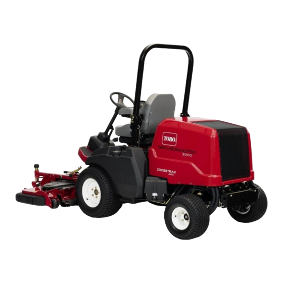
Toro Groundsmaster 3300 Series Operator's Manual
All-wheel drive traction unit
Hide thumbs
Also See for Groundsmaster 3300 Series:
- Operator's manual (36 pages) ,
- Installation instructions manual (12 pages) ,
- Installation instructions (2 pages)
Table of Contents

Related Manuals for Toro Groundsmaster 3300 Series


Summary of Contents for Toro Groundsmaster 3300 Series
- Page 1 Form No. 3438-812 Rev A Groundsmaster ® 3300 or 3310 All-Wheel Drive Traction Unit Model No. 31902—Serial No. 400000000 and Up Model No. 31903—Serial No. 400000000 and Up *3438-812* A Register at www.Toro.com. Original Instructions (EN)
-
Page 2: Figure 1
Section 4442 or 4443 to use or operate the engine on additional information, contact an Authorized Service any forest-covered, brush-covered, or grass-covered Dealer or Toro Customer Service and have the model land unless the engine is equipped with a spark and serial numbers of your product ready. -
Page 3: Table Of Contents
Resetting the PTO Function......34 Shutting Off the Engine........34 After Operation ............ 34 g000502 After Operation Safety ........34 Figure 2 Servicing the Cutting Unit ......... 34 Safety-alert symbol Towing the Machine .......... 37 Hauling the Machine ......... 37 Maintenance ............ -
Page 4: Safety
Safety Checking the Hydraulic-Fluid Level....58 Changing the Hydraulic Fluid and Filters ............59 This machine has been designed in accordance with Checking the Hydraulic Lines and ANSI B71.4-2017 and with EN ISO 5395 when you Hoses............59 complete the setup procedures and install the CE Kit, Cab Maintenance .......... -
Page 5: Safety And Instructional Decals
Safety and Instructional Decals Safety decals and instructions are easily visible to the operator and are located near any area of potential danger. Replace any decal that is damaged or missing. decal106-9206 106-9206 decalbatterysymbols 1. Wheel torque specifications Battery Symbols 2. - Page 6 decal133-8062 133-8062 decal115-8155 115-8155 1. Warning—read the Operator's Manual, do not prime or use starting fluid. decal138-2748 138-2748 1. Refer to the Operator’s 3. Fan and interior light Manual for fuse information. 2. Windshield washer decal125-9688 125-9688 1. Off 3. On 2.
- Page 7 decal138-7472 138-7472 decal138-7471 138-7471 1. Fast 2. Slow 1. Engine—start 5. Push down to disengage the cutting blade. 2. Engine—run 6. Deck—lower 3. Engine—stop 7. Deck—raise 4. Lift up to engage the cutting blade. decal139-6215 139-6215 1. Warning—read the 5. Cutting/dismemberment Operator’s Manual;...
- Page 8 decal139-6246 139-6246 Note: This machine complies with the industry standard stability test in the static lateral and longitudinal tests with the maximum recommended slope indicated on the decal. Review the instructions for operating the machine on slopes in the Operator’s Manual as well as the conditions in which you would operate the machine to determine whether you can operate the machine in the decal139-6218...
- Page 9 decal140-1460 140-1460 1. To move the machine 3. To adjust the steering forward, press forward on wheel, press the tilt lever. the pedal. 2. To move the machine backward, press backward on the pedal. decal140-3126 140-3126 1. Read the Operator’s 5.
-
Page 10: Setup
Install the tie-down bracket (Model No. Bolt (3/8 x 3-1/4 inches) 31902 only). Nut (3/8 inch) Seat Kit (ordered separately; refer to Install the seat (Model No. 31902 only). your authorized Toro distributor) Steering wheel Install the steering wheel (Model No. 31902 only). Cover Bumper Bolt (3/8 x 2-3/4 inches) Install the bumper (Model 31902 only). -
Page 11: Removing The Machine From The Shipping Container
Removing the Machine from the Shipping Container Model No. 31902 Only No Parts Required Procedure g299549 Remove the screws that hold down the rear Figure 3 wheel hubs to the pallet. 1. Wheel hub 3. Lug nut Cut the cable tie that holds the driveshaft to the 2. -
Page 12: Installing The Lift-Arm Assembly
g312023 g299550 Figure 5 Figure 4 Right side shown. 1. Wheel hub 3. Lug nut 1. Lift arm 3. Large pin 2. Tire 2. Machine frame 4. Grease fitting Removed the wheels from the wheel hubs (Figure 11). Install the grease fittings to the large pins (Figure Use 2 nuts (3/8 inch) and 2 bolts (3/8 x 2-3/4 inches) to secure the large pins to the frame... - Page 13 g312025 g312028 Figure 9 Figure 7 Right side shown. 1. Manifold 3. Hose swivel nut 2. Port C1 1. Sensor bracket 3. Nut (3/8 inch) 2. Carriage bolt Use a drift punch to align the cylinder rod holes with the lift-arm holes (Figure 10).
-
Page 14: Installing The Front Tires
Installing the Front Tires Installing the Tie-Down Bracket Model No. 31902 Only Model No. 31902 Only No Parts Required Parts needed for this procedure: Procedure Tie-down bracket Use the previously-removed lug nuts to secure Bolt (3/8 x 3-1/4 inches) the tires to the wheel hubs (Figure 11). -
Page 15: Installing The Seat
Installing the Seat Model No. 31902 Only Parts needed for this procedure: Seat Kit (ordered separately; refer to your authorized Toro distributor) Procedure Install the seat; refer to the Seat Kit Installation Instructions. Installing the Steering g307379 Figure 13 Wheel 1. -
Page 16: Installing The Bumper
Installing the Bumper Model No. 31902 Only Parts needed for this procedure: Bumper Bolt (3/8 x 2-3/4 inches) Bolt (3/8 x 3-1/4 inches) Nut (3/8 inch) Procedure Remove the bumper from the shipping skid. Use 4 bolts (3/8 x 3-1/4 inches) and 4 nuts (3/8 inch) to secure the upper area of the bumper to the machine frame (Figure... -
Page 17: Installing The Attachment
Parts needed for this procedure: No Parts Required Attachment (ordered separately; refer to your Procedure authorized Toro distributor) Bolt (5/16 x 2 inches) Before you start the engine for the first time, perform Nut (5/16 inch) the following fluid-level checks: •... -
Page 18: Adjusting The Weight Transfer Of The Attachment
Adjusting the Weight Transfer of the Attachment No Parts Required Procedure Perform this procedure only if you are installing an attachment other than the standard rotary cutting units (e.g., snowthrower, blade, or flail). g299920 You can change the hydraulic pressure used to Figure 16 transfer the weight of the attachment to the traction unit by adjusting the weight-transfer valve of the... -
Page 19: Product Overview
Product Overview the recommended pressure setting for the attachment. • Rotate the adjusting screw clockwise to increase the pressure. • Rotate the adjusting screw counterclockwise to decrease the pressure. Attachment Weight-Transfer Pressure Rotary cutting unit 1,724 kPa (250 psi) Flail Mower (Model No. 1,379 kPa (200 psi) 02835) Snowthrower... -
Page 20: Console
To get maximum power under heavy load or when ascending a hill, have the throttle in the F position while pressing traction pedal slightly to keep the engine speed (rpm) high. If the engine speed begins to decrease rapidly, release the traction pedal slightly to allow the engine speed to increase. -
Page 21: Cab Controls
Attachment Lift Switch Display Screen Button The attachment lift switch raises the attachment to the Refer to Using the Display-Screen Button (page 27). highest position (i.e., the T position) and RANSPORT lowers the attachment to the lowest position (i.e., the Cab Controls ) position. -
Page 22: Specifications
Specifications Note: Specifications and design are subject to change without notice. g302841 Figure 23... -
Page 23: Width Specifications
Contact before adjusting, servicing, cleaning, or storing it. your Authorized Service Dealer or authorized Toro distributor or go to www.Toro.com for a list of all • Know how to stop the machine and shut off the approved attachments and accessories. -
Page 24: Checking The Machine Daily
Replace worn or damaged blades and bolts in sets Check the air pressure in the front and rear tires. Add to preserve balance. or remove air as needed to set the air pressure in the tires to the tire air pressure specification. •... -
Page 25: Checking The Safety-Interlock System
Fuel filter plugging may occur for period after g287495 converting to biodiesel blends. Figure 25 • Contact your authorized Toro distributor if you wish for more information on biodiesel. Checking the Filling the Fuel Tank Safety-Interlock System Fuel tank capacity: 45 L (12 US gallons) -
Page 26: Adjusting The Roll Bar
Lowering the Roll Bar there is a malfunction in the safety-interlock Important: Lower the roll bar only when system. Refer to your authorized Toro absolutely necessary. distributor. With the engine running and the PTO switch set Park the machine on a level surface, engage the... -
Page 27: Understanding The Display-Screen Information
g034169 g034168 Figure 27 Understanding the Display-Screen Information The display screen shows information about your g034164 machine, such as the operating status, various Figure 26 diagnostics, and other information about the machine. There are two main-information screens (Figure and a main menu screen. Raising the Roll Bar Park the machine on a level surface, engage the parking brake, lower the cutting unit, shut off the... -
Page 28: Main Menu
ENUS machine faults. Refer to by your company with the the Service Manual or your PIN code to access protected authorized Toro distributor menus (i.e., the slope sensor for more information on the setting and the ability to clear menu. - Page 29 The factory default PIN code for you machine is “1234”. Display-Screen Icons If you changed the PIN code and forgot the code, Engine speed contact your authorized Toro distributor for assistance. Select the S option. ETTINGS Select the P option.
-
Page 30: During Operation
Slow down and use caution when making turns Roll Bar and crossing roads and sidewalks with the • machine. Always yield the right-of-way. A cab installed by Toro is a roll bar. • • Disengage the drive to the cutting unit, shut Always wear your seat belt. -
Page 31: Understanding The Diesel-Particulate Filter And Regeneration
Understanding the • Lower a folding roll bar temporarily only when necessary. Do not wear the seat belt when the Diesel-Particulate Filter roll bar is folded down. • Be aware that there is no rollover protection when and Regeneration a folded roll bar is in the down position. •... - Page 32 Types of diesel particulate filter regeneration • Notes that a regeneration is acknowledged that require you to park the machine: Regeneration Conditions that DPF description of Type cause DPF operation • Notes that a regeneration is in progress and regeneration the exhaust temperature is elevated Occurs because the •...
- Page 33 Time Since Last Regeneration Performing a Parked or Recovery Regeneration Access the DPF Regeneration menu, and scroll to the L option. EGEN When a parked regeneration is requested by the engine computer, follow the messages on the Use the L field to determine how EGEN InfoCenter.
-
Page 34: Starting The Engine
After Operation Canceling a Parked or Recovery Regeneration Use the P or R ARKED EGEN ANCEL ECOVERY EGEN setting to cancel a running parked or recovery ANCEL After Operation Safety regeneration process. Access the DPF Regeneration menu, scroll General Safety down to the P option or the ARKED... - Page 35 Press the lift switch to raise the cutting unit to the T position. RANSPORT Engage the parking brake, shut off the engine, and remove the key. Remove the pins from the height-of-cut plates (Figure 31). g258474 Figure 31 1. Height-of-cut pins 2.
- Page 36 g298276 Figure 33 Rotating the Cutting Unit to the Position RANSPORT Perform this procedure to rotate the cutting unit from the S position to the T position. ERVICE RANSPORT Release the cutting-unit latch from the tie-down bracket (Figure 34) by slightly rotating the cutting unit slightly forward (refer to Figure 32) and...
-
Page 37: Towing The Machine
Towing the Machine If it becomes necessary to tow or push the machine, the traction pump must be set to bypass hydraulic fluid. Move the machine at a speed below 4.8 kph (3 mph), and for a very short distance. Important: If towing limits are exceeded, severe damage to the hydraulic pump may occur. -
Page 38: Maintenance
Download a free copy of the electrical or • If possible, do not perform maintenance while the hydraulic schematic by visiting www.Toro.com and engine is running. Keep away from moving parts. searching for your machine from the Manuals link on the home page. -
Page 39: Daily Maintenance Checklist
Maintenance Service Maintenance Procedure Interval • Change the air-cleaner element. • Check and clean the cooling fins (clean them more frequently in dirty or dusty Every 250 hours conditions). • Replace the fuel/water separator. • Replace the fuel filter. • Inspect the fuel lines and connections. Every 400 hours •... -
Page 40: Pre-Maintenance Procedures
Maintenance Check Item For the week of: Mon. Tues. Wed. Thurs. Fri. Sat. Sun. Check the instrument operation. Lubricate all the grease fittings. Touch up any damaged paint. Inspect the seat belt. Check the glow plug and injector nozzles if the engine is hard to start, there is excess smoke, or the engine runs rough Immediately after every washing, regardless of the interval listed If the indicator shows red Notation for Areas of Concern... -
Page 41: Raising The Hood
Raising the Rear of the Machine Important: Ensure that no cables or hydraulic components are between the jack and the frame. g299730 Figure 38 1. Rear of the machine 3. Rear jack stand point—frame tube 2. Rear jacking point—frame tube Chock the 2 front wheels with chocks to prevent the machine from moving. -
Page 42: Lubrication
Lubrication Greasing the Bearings and Bushings Service Interval: Before each use or daily—Grease the PTO driveshaft (cross-bearings and telescoping splines). Every 50 hours—Grease the bearings and bushings. The machine has grease fittings that you must g303694 Figure 41 lubricate regularly with No. 2 lithium grease. 1. - Page 43 g285509 Figure 43 Front of the machine 1. Attachment pin joints 3. Lift-arm pin joints 2. Lift-cylinder bushings • Rear of the machine (Figure 44): – Axle spindle hubs (2) – Hydraulic-cylinder ball joint (2) – Tie-rod ends (2) g285510 Figure 44 Rear of the machine (bumper removed) 1.
-
Page 44: Engine Maintenance
Changing the Engine Oil and Filter temperatures) Service Interval: Every 500 hours Toro Premium Engine Oil is available from your authorized Toro distributor in either 15W-40 or 10W-30 Start the engine and let it run 5 minutes to allow viscosity grades. - Page 45 g297639 Figure 46 Change the engine-oil filter as shown in Figure g031261 Note: Figure 47 Ensure that the oil-filter gasket touches the engine, and then an extra 3/4 turn is completed.
-
Page 46: Servicing The Air Cleaner
Servicing the Air Cleaner Service Interval: Before each use or daily—Check the air-cleaner restriction indicator and replace the filter elements if necessary. Every 250 hours—Change the air-cleaner element. Check the air-cleaner body for damage, which could cause an air leak. Replace the body if it is damaged. Check the intake system for leaks, damage, or loose hose clamps Service the air-cleaner element only when the... -
Page 47: Fuel System Maintenance
Fuel System Maintenance DANGER Under certain conditions, diesel fuel and fuel vapors are highly flammable and explosive. A fire or explosion from fuel can burn you and others and can cause property damage. Never smoke when handling fuel, and stay away from an open flame or where a spark may ignite fuel fumes. -
Page 48: Cleaning The Fuel Tank
Electrical System Maintenance Electrical System Safety • Disconnect the battery before repairing the machine. Disconnect the negative terminal first and the positive last. Connect the positive terminal first and the negative last. • Charge the battery in an open, well-ventilated area, away from sparks and flames. -
Page 49: Disconnecting The Battery
Disconnecting the Battery Connecting the Battery WARNING WARNING Battery terminals or metal tools could short Incorrect battery cable routing could damage against metal components, causing sparks. the machine and cables, causing sparks. Sparks can cause the battery gasses to Sparks can cause the battery gasses to explode, resulting in personal injury. -
Page 50: Removing Or Installing The Battery
Wash the entire case with a solution of baking soda and water. Coat both battery posts and cable connectors with Grafo 112X (skin-over) grease (Toro Part No. 505-47) to prevent corrosion. Slide the rubber insulator over the positive terminal. g285614 Close the battery cover. - Page 51 Refer to the Traction-Unit Fuse Block (page 51) table for a description of each fuse on the traction-unit fuse block (Figure 58): g285656 Figure 59 1. Fuse box cover 3. Cab fuses 2. Thumb screw g289587 Figure 58 Refer to the Cab Fuse Block (page 51) table for a description of each fuse on the traction-unit fuse block...
-
Page 52: Drive System Maintenance
Drive System Cooling System Maintenance Maintenance Cooling System Safety Torquing the Wheel-Lug • Nuts Swallowing engine coolant can cause poisoning; keep out of reach from children and pets. Service Interval: After the first hour • Discharge of hot, pressurized coolant or touching a hot radiator and surrounding parts can cause After the first 10 hours severe burns. -
Page 53: Checking The Hood-Air-Intake Screen
Important: Do not use water only or WARNING alcohol-based coolants. If the engine has been running, the radiator Do not fill past the F ) mark on the pressurizes and the coolant inside is hot. If tank. you remove the cap, coolant may spray out, Install the expansion-tank cap. -
Page 54: Inspecting The Cooling-System Hoses
Brake Maintenance Checking and Adjusting the Parking Brake Service Interval: Every 400 hours Checking the Parking Brake Place jack stands under the front of the machine; refer to Raising the Front of the Machine (page 40). Remove the front wheels. Move the parking brake to the D ISENGAGED position;... -
Page 55: Belt Maintenance
Belt Maintenance Checking the Alternator-Belt Tension Service Interval: After the first 10 hours After the first 50 hours Every 100 hours Proper tension of the belt allows 10 mm (3/8 inch) of deflection when a force of 4.5 kg (10 lb) is applied on the belt midway between the pulleys. - Page 56 Replacing the Traction Belt g300592 g300570 Figure 70 Figure 69 1. Clutch wire harness 3. Bolt, washer, and nut 1. Traction belt 4. Idler pulley 2. Rubber strap 2. Insert ratchet here. 5. Engine pulley 3. Pump pulley Remove the bolt, washer, and nut from the rubber strap (Figure 70) on the frame.
-
Page 57: Controls System Maintenance
208 L (55 US gallon) drums. Note: A machine using the recommended replacement fluid requires less frequent fluid and filter changes. Alternative hydraulic fluids:If Toro PX Extended Life Hydraulic Fluid is not available, you may use another g299611 conventional, petroleum-based hydraulic fluid having Figure 71 specifications that fall within the listed range for all the 1. -
Page 58: Checking The Hydraulic-Fluid Level
2 marks on the dipstick gallons) of hydraulic fluid. Order Part No. 44-2500 (B in Figure 73). from your authorized Toro distributor. Checking the Hydraulic-Fluid Level Service Interval: Before each use or daily Park the machine on a level surface, lower the cutting unit, engage the parking brake, shut off the engine, and remove the key. -
Page 59: Changing The Hydraulic Fluid And Filters
Every 2,000 hours—Change the hydraulic fluid. damage. If the hydraulic fluid becomes contaminated, contact Install the drain plug when the hydraulic fluid your authorized Toro distributor; the system must be stops draining. flushed. Contaminated fluid looks milky or black when compared to clean fluid. -
Page 60: Cab Maintenance
Cab Maintenance Cleaning the Cab Important: Use care around the cab seals (Figure 75). If you are using a pressure washer, keep the washer wand at least 0.6 m (2 ft) away from the machine. Do not use the pressure washer directly on the cab seals or under the rear overhang. -
Page 61: Replacing The Dome Light
Filling the Windshield-Wiper-Fluid Reservoir Note: The windshield-wiper-fluid reservoir is located next to the engine on the right side of the machine. Remove the cap (Figure 79) on the reservoir. g032951 Figure 77 1. Latch-mount assembly 3. Screen cover 2. Condenser filter Replacing the Dome Light Note: Refer to the Parts Catalog for the appropriate... -
Page 62: Storage
Storage Storage Safety • Shut off the engine, remove the key, and wait for all movement to stop before you leave the operator’s position. Allow the machine to cool before adjusting, servicing, cleaning, or storing it. • Do not store the machine or fuel container where there is an open flame, spark, or pilot light, such as on a water heater or other appliance. - Page 63 Notes:...
- Page 64 Notes:...
- Page 65 Notes:...
- Page 66 The Toro Company (“Toro”) respects your privacy. When you purchase our products, we may collect certain personal information about you, either directly from you or through your local Toro company or dealer. Toro uses this information to fulfil contractual obligations - such as to register your warranty, process your warranty claim or to contact you in the event of a product recall - and for legitimate business purposes - such as to gauge customer satisfaction, improve our products or provide you with product information which may be of interest.
- Page 67 Countries Other than the United States or Canada Customers who have purchased Toro products exported from the United States or Canada should contact their Toro Distributor (Dealer) to obtain guarantee policies for your country, province, or state. If for any reason you are dissatisfied with your Distributor's service or have difficulty obtaining guarantee information, contact your Authorized Toro Service Center.
- Page 68 While the exposure from Toro products may be negligible or well within the “no significant risk” range, out of an abundance of caution, Toro has elected to provide the Prop 65 warnings. Moreover, if Toro does not provide these warnings, it could be sued by the State of California or by private parties seeking to enforce Prop 65 and subject to substantial penalties.