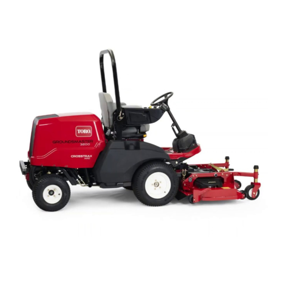
Toro Groundsmaster 3200 Series Installation Instructions Manual
Traction unit with winter enclosure
Hide thumbs
Also See for Groundsmaster 3200 Series:
- Service manual (274 pages) ,
- Operator's manual (44 pages) ,
- Installation instructions manual (24 pages)
Advertisement
Quick Links
Sound Reducing Kit
Groundsmaster
Enclosure
Model No. 140-6721
Installation
The Sound Reducing Kit can be installed on the
following:
•
Traction units (Models 31903 and 31909)
•
Winter enclosure (Model 31990)
1
Preparing the Machine
No Parts Required
Procedure
1.
Park the machine on a level surface.
2.
Engage the parking brake.
3.
Lower the attachment.
4.
Shut off the engine and remove the key.
5.
Disconnect the battery; refer to the electrical
system maintenance section in your Operator's
Manual.
© 2021—The Toro® Company
8111 Lyndale Avenue South
Bloomington, MN 55420
®
3200 or 3300 Series Traction Unit with Winter
Installing the Floor
Components
Parts needed for this procedure:
Register at www.Toro.com.
Installation Instructions
2
1
Steering plug
1
Upper steering plug
1
Lower steering plug
1
Steering pad
3
Mounting-tab plug
1
Corner floor pad
1
Center floor pad
1
Brake plug—7.6 cm (3 inches) width
1
Brake plug—3.1 cm (1.22 inch) width
4
ROPS plug
1
Seat-base pad (thin)
1
Seat-base pad (thick)
1
Seat pad
1
Rear-window pad
1
Lower-firewall pad
1
Upper-firewall pad
1
Firewall tile pad
1
Upper brake foam
1
Lower brake foam
1
Right corner pad
1
Left corner pad
Original Instructions (EN)
Printed in the USA
All Rights Reserved
Form No. 3445-275 Rev A
*3445-275*
Advertisement

Summary of Contents for Toro Groundsmaster 3200 Series
- Page 1 Firewall tile pad Upper brake foam Lower brake foam Right corner pad Left corner pad *3445-275* © 2021—The Toro® Company Original Instructions (EN) Register at www.Toro.com. 8111 Lyndale Avenue South Printed in the USA Bloomington, MN 55420 All Rights Reserved...
- Page 2 Installing the Steering Cover and Steering-Column Plugs Remove the fasteners and lift the steering cover up out of the way (Figure Note: While you install the plugs/pads in this procedure, you can use string to secure the steering cover to the steering wheel. g332885 Figure 3 2.
- Page 3 g331281 Figure 7 1. Steering plug (PSA) 2. Steering cover (cutaway view shown) g330591 Figure 5 1. Lower steering plug (PSA) Remove the backing film and install the steering (Figure g331294 Figure 8 g330645 Top view Figure 6 1. Steering plug 1.
-
Page 4: Removing The Seat
g330624 g330592 Figure 11 Figure 9 1. Corner floor pad (PSA) 2. Center floor pad (PSA) 1. Steering cover 2. Bolt Removing the Seat Installing the Floor Pads Remove the rubber floor mat (Figure 10). Perform the following steps to remove the seat from the seat base: Remove the nuts that secures the seat to the seat base... - Page 5 Installing the Brake Cover and Remove the backing film from the top of the upper brake-cover foam, and install it to the Plugs brake cover (Figure 15). Remove the push-in fasteners that secure the Figure 16 shows a top and cutaway (side) view brake cover to the floor (Figure 13).
- Page 6 Installing the Firewall Pads Remove the backing film and install the lower-firewall pad (Figure 17). g331283 Figure 16 1. Top view 3. Upper brake foam (PSA—both sides) 2. Cutaway (side) view 4. Lower brake foam Remove the backing film from the bottom side of the upper brake-cover foam (Figure 15).
- Page 7 Remove the backing film and install the rear-window pad (Figure 18). Installing the Seat Pads Install the seat-base pad (thin) inside of the seat base (Figure 19). g330729 Figure 19 1. Seat-base pad (thick) 3. Seat base 2. Seat-base pad (thin) Install the seat-base pad (thick) inside of the g330728 seat base...
- Page 8 Installing the Corner Pads Remove the backing film and install the corner pads as shown in Figure Installing the Upper-Frame Components Parts needed for this procedure: Rear-pillar pad Left door-side pad Right door-side pad Upper-ceiling pad Lower-ceiling pad Mount-panel pad Left rear-pillar cover g330727 Right rear-pillar cover...
- Page 9 Figure 27 shows the proper dimensions for installing the outer-pillar pads and sound-dampening panels to the rear-pillar covers. g330652 Figure 24 Left side shown 1. Mount-panel bracket 3. Bolt 2. Rear-side cover Install the rear-pillar pads over the hoses and wire harness (Figure 25).
- Page 10 g330646 Figure 28 Left side shown 1. Mount-panel bracket 3. Rear-pillar-cover assembly 2. Rear-pillar pad 4. Bolt Installing the Ceiling Pads Remove the backing film and install the ROPS g331309 pads to the ROPS mounts (Figure 29). Figure 27 Left-sided panel shown 1.
- Page 11 Installing the Door-Side Pads Remove the backing film and install the door-side pads as shown in Figure g330650 Figure 30 1. Rear cab window (PSA) 2. Lower-ceiling pad (PSA) Remove the backing film and install the upper-ceiling pad to the ROPS mount bracket (Figure 31).
- Page 12 Install the Mount-Panel Pads Installing the Rubber Floor Mat Remove the backing film and install the mount-panel Assemble the rubber floor mat to the floor of the pads to the sides of the cab control panel as shown machine (Figure 35).


