Table of Contents
Advertisement
Quick Links
Advertisement
Table of Contents

Related Manuals for Toro Groundsmaster 3200 Series


Summary of Contents for Toro Groundsmaster 3200 Series
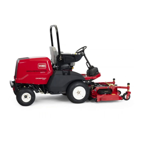
- Page 1 Form No. 3443-939 Rev C 60in or 72in Rear Discharge Rotary Mower Groundsmaster ® 3200 or 3300 Series Traction Unit Model No. 31971—Serial No. 407970000 and Up Model No. 31973—Serial No. 407850000 and Up *3443-939* Register at www.Toro.com. Original Instructions (EN)
- Page 2 Whenever you need service, genuine Toro parts, or additional information, contact an Authorized Service Dealer or Toro Customer Service and have the model g000502 and serial numbers of your product ready. Figure 1...
-
Page 3: Table Of Contents
Contents Safety Safety ............... 3 This machine has been designed in accordance with General Safety ........... 3 EN ISO 5395 (when equipped with the CE Kit) and Cutting Unit Safety..........3 ANSI B71.4-2017. Safety and Instructional Decals ......4 Setup ................ 8 General Safety 1 Preparing the Machine........ -
Page 4: Safety And Instructional Decals
• Use only accessories, attachments, and replacement parts approved by Toro. Safety and Instructional Decals Safety decals and instructions are easily visible to the operator and are located near any area of potential danger. Replace any decal that is damaged or missing. - Page 5 decal127-0326 127-0326 decal139-6303 139-6303 1. Read the Operator's 3. Remove the key and Manual. read the Operator's 1. Entanglement hazard—read the Operator’s Manual; stay Manual before performing away from moving parts; keep all guards and shields in maintenance. place. 2. Height of cut Model 31973 only: decal133-8061 133-8061...
- Page 6 Model 31973 only: Model 31971 only: decal144-0541 decal144-0543 144-0541 144-0543 1. Height of cut 1. Height of cut Model 31971 only: decal144-0542 144-0542 1. Height of cut...
- Page 7 decal137-5949 137-5949 1. Height of cut 2. Mounting holes...
-
Page 8: Setup
Setup Loose Parts Use the chart below to verify that all parts have been shipped. Procedure Description Qty. – No parts required Prepare the machine. – No parts required Install the CE kit (if required). Debris guard Bracket Install the debris guard to the front axle. Rivet Hex-head bolt Washer... -
Page 9: Installing The Cutting Unit To The Traction
Installing the Debris Guard Installing the Cutting Unit to the Front Axle to the Traction Unit Parts needed for this procedure: Parts needed for this procedure: Debris guard Hex-head bolt Bracket Washer Rivet Height-of-cut pin Procedure Procedure Park the machine on a level surface, move Use 5 rivets to install the bracket and debris guard to the lift arms to the lowest position, engage the the front axle... -
Page 10: Installing The Pto Cover
Use 2 hex-head bolts and 2 washers to secure the castor arms to the lift arms (Figure If you have previously used the bolts to install the cutting unit: Apply thread-locking compound to the threads of the bolts. g296657 Figure 6 g296375 Figure 5 1. -
Page 11: Greasing The Cutting Unit
Tighten the jam nuts. To ensure optimum performance and continued safety certification of the machine, use only genuine Toro replacement parts and accessories. Replacement parts and accessories made by other manufacturers could be dangerous, and such use could void the product warranty. -
Page 12: Operation
Operation Note: Determine the left and right sides of the machine from the normal operating position. CAUTION If you leave the key in the ignition switch, someone could accidently start the engine and seriously injure you or other bystanders. Remove the key from the ignition before you do any maintenance. -
Page 13: Adjusting The Cutting-Unit Pitch
Adjusting the Cutting-Unit Refer to Figure 9 to determine the combinations of spacers for your desired height-of-cut setting. Pitch Note: You may use the shims in any combination above or below the castor-arm hub A blade pitch of 6 to 9.5 mm (1/4 to 3/8 inch) is (as required) to achieve the desired height of recommended (i.e., the back of the blade plane is 6 cut or cutting-unit level. -
Page 14: Adjusting The Anti-Scalp Rollers
Adjusting the Anti-Scalp Adjusting the Skid Rollers Mount the skid in the lower position when operating in height of cuts higher than 64 mm (2-1/2 inches) and Whenever you change the height-of-cut, adjust the in the higher position when operating in height of cuts height of the anti-scalp rollers (Figure 12). -
Page 15: Operating Tips
• If a blade is damaged or worn, replace it Cutting Speed immediately with a genuine Toro replacement blade. Refer to Removing and Installing the To improve cut quality, use a slower ground speed. Cutting-Unit Blade(s) (page 20). -
Page 16: Maintenance
Maintenance Note: Determine the left and right sides of the machine from the normal operating position. Recommended Maintenance Schedule(s) Maintenance Service Maintenance Procedure Interval • Tighten the castor wheel nuts. After the first 2 hours • Check the PTO driveshaft-to-gearbox fastener torque. After the first 10 hours •... -
Page 17: Greasing The Bearings And Bushings
Greasing the Bearings and After the first 50 hours Every 400 hours Bushings The gearbox in designed to operate on SAE 80-90 Service Interval: Every 50 hours Lubricate the weight gear lube. Although the gearbox comes with grease fittings immediately after lubricant from the factory, check the level before every washing. -
Page 18: Removing The Cutting Unit From The Traction Unit
g296375 Figure 20 1. Lift arm 3. Washer g299646 2. Castor arm 4. Bolt Figure 18 1. Gearbox 3. PTO driveshaft Remove the bolts and nuts from the PTO shaft 2. Bolts and nuts (Figure 21) and slide the yoke out of the gearbox. Note: Refer to the Operator’s Manual, to properly align the splines if you separate the... -
Page 19: Servicing The Bushings In The Castor Arms
Servicing the Bushings in Remove the locknut from the bolt holding the castor wheel assembly between the castor fork the Castor Arms (Figure 23). Grasp the castor wheel and slide the bolt out of the fork or pivot arm. The castor arms have bushings pressed into the top Remove the bearing from the wheel hub and and bottom of the tube, and after many hours of allow the bearing spacer to fall out... - Page 20 Raise the cutting unit to the S position; ERVICE of balance, or is bent. Always use genuine Toro refer to your traction unit Operator’s Manual. replacement blades to ensure safety and optimum Examine the cutting ends of the blade carefully, performance.
-
Page 21: Checking And Correcting Mismatch Of Blades
Note: Remove the blades and sharpen them on a grinder. After sharpening the cutting edges, install the blade with the anti-scalp cup and blade bolt; refer to Inspecting and Sharpening the Cutting Unit Blade(s) (page 20). Checking and Correcting Mismatch of Blades If there is mismatch between the blades, the grass will appear streaked when it is cut. -
Page 22: Replacing The Drive Belt
Replacing the Drive Belt The blade drive belt, tensioned by the spring-loaded idler pulley, is very durable. However, after many hours of use, the belt will show signs of wear. Signs of a worn belt are squealing when belt is rotating, blades slipping when cutting grass, frayed edges, burn marks, and cracks. -
Page 23: Storage
Storage Disengage the PTO, release the traction pedal to the neutral position, and engage the parking brake. Shut off the engine, remove the key, and wait for all moving parts to stop before leaving the operator’s position. Allow the engine to cool before adjusting, cleaning, storing, or repairing the machine. - Page 24 Notes:...
- Page 25 The method of transmission shall be electronic transmittal. This machinery shall not be put into service until incorporated into approved Toro models as indicated on the associated Declaration of Conformity and in accordance with all instructions, whereby it can be declared in conformity with all relevant Directives.
- Page 26 While the exposure from Toro products may be negligible or well within the “no significant risk” range, out of an abundance of caution, Toro has elected to provide the Prop 65 warnings. Moreover, if Toro does not provide these warnings, it could be sued by the State of California or by private parties seeking to enforce Prop 65 and subject to substantial penalties.
- Page 27 The Toro Company (“Toro”) respects your privacy. When you purchase our products, we may collect certain personal information about you, either directly from you or through your local Toro company or dealer. Toro uses this information to fulfil contractual obligations - such as to register your warranty, process your warranty claim or to contact you in the event of a product recall - and for legitimate business purposes - such as to gauge customer satisfaction, improve our products or provide you with product information which may be of interest.
- Page 28 Countries Other than the United States or Canada Customers who have purchased Toro products exported from the United States or Canada should contact their Toro Distributor (Dealer) to obtain guarantee policies for your country, province, or state. If for any reason you are dissatisfied with your Distributor's service or have difficulty obtaining guarantee information, contact your Authorized Toro Service Center.