Table of Contents
Advertisement
Quick Links
Advertisement
Table of Contents

Related Manuals for Toro Groundsmaster 3200 Series


Summary of Contents for Toro Groundsmaster 3200 Series
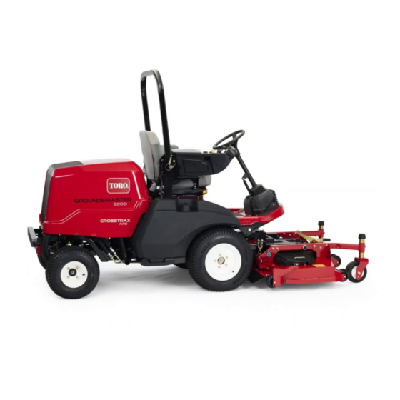
- Page 1 Form No. 3440-545 Rev A 60in or 72in Rear Discharge Rotary Mower Groundsmaster ® 3200 or 3300 Series Traction Unit Model No. 31974—Serial No. 400000000 and Up Model No. 31975—Serial No. 400000000 and Up *3440-545* A Register at www.Toro.com. Original Instructions (EN)
- Page 2 Whenever you need service, genuine Toro parts, or Serial No. additional information, contact an Authorized Service Dealer or Toro Customer Service and have the model This manual identifies potential hazards and has and serial numbers of your product ready. Figure 1...
-
Page 3: Table Of Contents
Contents Safety Safety ............... 3 This machine has been designed in accordance with General Safety ........... 3 EN ISO 5395 and ANSI B71.4-2017. Cutting Unit Safety..........3 Safety and Instructional Decals ......4 General Safety Setup ................ 7 1 Preparing the Machine........7 This product is capable of amputating hands and 2 Installing the Debris Guard to the Front feet and of throwing objects. -
Page 4: Safety And Instructional Decals
• Use only accessories, attachments, and replacement parts approved by Toro. Safety and Instructional Decals Safety decals and instructions are easily visible to the operator and are located near any area of potential danger. Replace any decal that is damaged or missing. - Page 5 decal127-0326 127-0326 decal139-6348 139-6348 1. Read the Operator's 3. Remove the key and Manual. read the Operator's 1. Height of cut (inches/millimeters) Manual before performing maintenance. 2. Height of cut decal138-7359 138-7359 decal139-6349 139-6349 1. Grease every 50 hours. 2. Belt routing 1.
- Page 6 decal137-5949 137-5949 1. Height of cut 2. Mounting holes...
-
Page 7: Setup
Setup Loose Parts Use the chart below to verify that all parts have been shipped. Procedure Description Qty. – No parts required Prepare the machine. Debris guard Bracket Install the debris guard to the front axle. Rivet Hex-head bolt Washer Install the cutting unit to the traction unit. -
Page 8: Installing The Cutting Unit To The Traction
Installing the Debris Guard Installing the Cutting Unit to the Front Axle to the Traction Unit Parts needed for this procedure: Parts needed for this procedure: Debris guard Hex-head bolt Bracket Washer Rivet Height-of-cut pin Procedure Procedure Park the machine on a level surface, move Use 5 rivets to install the bracket and debris guard to the lift arms to the lowest position, engage the the front axle... -
Page 9: Installing The Pto Cover
Use 2 hex-head bolts and 2 washers to secure the castor arms to the lift arms (Figure If you have previously used the bolts to install the cutting unit: Apply thread-locking compound to the threads of the bolts. g296657 Figure 6 g296375 Figure 5 1. -
Page 10: Greasing The Cutting Unit
Tighten the jam nuts. To ensure optimum performance and continued safety certification of the machine, use only genuine Toro replacement parts and accessories. Replacement parts and accessories made by other manufacturers could be dangerous, and such use could void the product warranty. -
Page 11: Operation
Operation Note: Determine the left and right sides of the machine from the normal operating position. CAUTION If you leave the key in the ignition switch, someone could accidently start the engine and seriously injure you or other bystanders. Remove the key from the ignition before you do any maintenance. -
Page 12: Adjusting The Cutting-Unit Pitch
Adjusting the Cutting-Unit Refer to Figure 9 to determine the combinations of spacers for your desired height-of-cut setting. Pitch Note: You may use the shims in any combination above or below the castor-arm hub A blade pitch of 6 to 9.5 mm (1/4 to 3/8 inch) is (as required) to achieve the desired height of recommended (i.e., the back of the blade plane is 6 cut or cutting-unit level. -
Page 13: Correcting A Cutting Unit Mismatch
Park the machine on a level surface, lower the cutting unit, engage the parking brake, shut off the engine, and remove the key. Set the cutting unit to the desired height of cut; refer to Adjusting the Height of Cut (page 11). - Page 14 Check the blades daily for sharpness and for any wear or damage. Sharpen the blades as necessary. • If a blade is damaged or worn, replace it immediately with a genuine Toro replacement blade. Refer to Removing and Installing the Cutting-Unit Blade(s) (page 19).
-
Page 15: Maintenance
Maintenance Note: Determine the left and right sides of the machine from the normal operating position. Recommended Maintenance Schedule(s) Maintenance Service Maintenance Procedure Interval • Tighten the castor wheel nuts. After the first 2 hours • Check the PTO driveshaft-to-gearbox fastener torque. After the first 10 hours •... -
Page 16: Greasing The Bearings And Bushings
Greasing the Bearings and Every 400 hours Bushings The gearbox in designed to operate on SAE 80-90 weight gear lube. Although the gearbox comes with lubricant from the factory, check the level before Service Interval: Every 50 hours Lubricate the operating the cutting unit. -
Page 17: Removing The Cutting Unit From The Traction Unit
g296375 Figure 19 1. Lift arm 3. Washer g299646 2. Castor arm 4. Bolt Figure 17 1. Gearbox 3. PTO driveshaft Remove the bolts and nuts from the PTO shaft 2. Bolts and nuts (Figure 20) and slide the yoke out of the gearbox. Removing the Cutting Unit from the Traction Unit Park the machine on a level surface with the... -
Page 18: Servicing The Bushings In The Castor Arms
Servicing the Bushings in Remove the locknut from the bolt holding the castor wheel assembly between the castor fork the Castor Arms (Figure 22). Grasp the castor wheel and slide the bolt out of the fork or pivot arm. The castor arms have bushings pressed into the top Remove the bearing from the wheel hub and and bottom of the tube, and after many hours of allow the bearing spacer to fall out... -
Page 19: Servicing The Cutting Blades
Removing and Installing the Cutting-Unit Blade(s) Blades Replace the blade if it hits a solid object, is out of balance, or is bent. Always use genuine Toro Blade Safety replacement blades to ensure safety and optimum performance. A worn or damaged blade can break, and a piece of... -
Page 20: Checking And Correcting Mismatch Of Blades
Check the blades for any wear or damage. The sail Examine the cutting edges of all of the blades lifts the grass up straight, thereby producing an even and sharpen the cutting edges if they are dull cut and gradually wears down during operation. or nicked (Figure 26). -
Page 21: Replacing The Drive Belt
10 mm (3/8 inch) lower than the outer blades, Remove the old belt from around the spindle proceed to step and add shims between the pulleys and idler pulley. spindle housing and the bottom of the cutting Using a torque wrench or similar tool to hold unit. -
Page 22: Storage
Storage Disengage the PTO, release the traction pedal to the neutral position, and engage the parking brake. Shut off the engine, remove the key, and wait for all moving parts to stop before leaving the operator’s position. Allow the engine to cool before adjusting, cleaning, storing, or repairing the machine. - Page 23 Notes:...
- Page 24 Notes:...
- Page 25 Notes:...
- Page 26 The method of transmission shall be electronic transmittal. This machinery shall not be put into service until incorporated into approved Toro models as indicated on the associated Declaration of Conformity and in accordance with all instructions, whereby it can be declared in conformity with all relevant Directives.
- Page 27 The Toro Company (“Toro”) respects your privacy. When you purchase our products, we may collect certain personal information about you, either directly from you or through your local Toro company or dealer. Toro uses this information to fulfil contractual obligations - such as to register your warranty, process your warranty claim or to contact you in the event of a product recall - and for legitimate business purposes - such as to gauge customer satisfaction, improve our products or provide you with product information which may be of interest.
- Page 28 Countries Other than the United States or Canada Customers who have purchased Toro products exported from the United States or Canada should contact their Toro Distributor (Dealer) to obtain guarantee policies for your country, province, or state. If for any reason you are dissatisfied with your Distributor's service or have difficulty obtaining guarantee information, contact your Authorized Toro Service Center.