Table of Contents
Advertisement
Chapter 1 Overview
1.1 Introduction to the Eudemon200 Firewall
1.2 Product Structure
1.3 System Parameters
1.4 Introduction to General Modules
1.4.1 RPU
1.4.2 PWR
1.4.3 FAN
................................................................................................
1.4.4 Interface Module
Chapter 2 Installation Preparation
2.1 Site Inspection
2.1.1 Equipment Room Environment
2.1.2 ESD Protection
2.1.3 Electromagnetic Environment
2.1.4 Lightning Protection
2.1.5 Workbench
2.2 Safety Recommendations
2.3 Checking Eudemon200 and Accessories
2.4 Installation Tools, Meters and Equipment
Chapter 3 Installation
3.1 Installation Flow
3.2 Mount a Eudemon200 to a Specified Place
3.2.1 Mounting a Eudemon200 into the Rack
3.2.2 Mount a Eudemon200 onto the Workbench
3.3 Connect the PGND
3.4 Connect Power Cable
3.4.1 Connect AC Power Cable
3.4.2 Connect DC-Input Power Cable
3.5 Connect the Console Terminal
3.6 Connect the Eudemon200 to LAN
3.7 Connect the Eudemon200 to WAN
3.8 Verify Installation
Chapter 4 Boot and Configuration
4.1 Boot the Eudemon200
4.1.1 Establish Configuration Environment
4.1.2 Power on the Eudemon200
4.1.3 Startup Process
4.2 Configuration Fundamentals
.........................................................................................
...................................................................................
................................................................................
...............................................................................................
...............................................................................................
............................................................................
........................................................................................
..............................................................................
.......................................................................
.....................................................................................
......................................................................
......................................................................................
......................................................................................
.................................................................................
............................................................................
....................................................................................
............................................................................
.............................................................................
...............................................
............................................................
.................................................................
......................................................
........................................................
...............................................
..............................................
...........................................
.........................................
..............................................................
.....................................................
...............................................................
..........................................................
........................................................
.................................................................
.............................................
...........................................................
..................................................................
..................................
1-1
1-1
1-3
1-5
1-6
1-6
1-9
1-11
1-12
2-1
2-1
2-1
2-1
2-2
2-2
2-3
2-3
2-3
2-5
3-1
3-1
3-2
3-2
3-3
3-3
3-4
3-4
3-5
3-7
3-8
3-9
3-11
4-1
4-1
4-1
4-4
4-5
4-7
Advertisement
Table of Contents
Troubleshooting

Related Manuals for Huawei Quidway Eudemon 200


Summary of Contents for Huawei Quidway Eudemon 200
- Page 1 Chapter 1 Overview ..................1.1 Introduction to the Eudemon200 Firewall ..........1.2 Product Structure ................... 1.3 System Parameters ................1.4 Introduction to General Modules ............1.4.1 RPU ....................1.4.2 PWR ....................1.4.3 FAN ....................1-11 1.4.4 Interface Module ................1-12 Chapter 2 Installation Preparation ..............
- Page 2 4.2.1 Basic Configuration Procedure ............4.2.2 Command Line Interface ..............4.2.3 Slot Arrangement and Interface Numbering Rules ......4.3 Software Maintenance ................Chapter 5 Hardware Maintenance ..............5.1 Tools Required ..................5.2 Power Module Removal and Installation ..........5.2.1 Remove a Power Module ...............
- Page 3 7.6.3 Panel and Interface LED ..............7-10 7.6.4 Interface Cable of 4E1 ..............7-10 7.6.5 Internal DIP Switch ................ 7-12 7.6.6 Connect Interface Cable ..............7-13 7.7 4T1 ......................7-14 7.7.1 Introduction ..................7-14 7.7.2 Interface Attributes ................. 7-14 7.7.3 Panel and Interface LED ..............
- Page 4 HUAWEI Quidway Eudemon 200 Firewall Installation Manual...
- Page 5 31040977 Huawei Technologies Co., Ltd. provides customers with comprehensive technical support and service. If you purchase the products from the sales agent of Huawei Technologies Co., Ltd., please contact our sales agent. If you purchase the products from Huawei Technologies Co., Ltd. directly, Please feel free to contact our local office, customer care center or company headquarters.
- Page 6 Copyright © 2004 Huawei Technologies Co., Ltd. All Rights Reserved No part of this manual may be reproduced or transmitted in any form or by any means without prior written consent of Huawei Technologies Co., Ltd. Trademarks , HUAWEI, C&C08, EAST8000, HONET,...
- Page 7 About This Manual Release Notes The product corresponding to this manual is Quidway Eudemon 200 Firewall. Related Manuals The following manuals provide more information about Quidway Eudemon 200 Firewall VRP3.20. Manual Content It provides information for the installation of Eudemon200...
- Page 8 Describes the boot and configuration essentials of Eudemon 200 simple application of command lines, list of interface configuration modes and introduction to names and sequences of interfaces. • Chapter 5 Hardware Maintenance Gives the hardware maintenance, including replacement of power module, blower module and various boards of Eudemon 200.
- Page 9 II. Command conventions Convention Description boldface font Command keywords (which must be input unchanged) are in boldface. italic font Command arguments for which you supply values are in italics. Elements in square brackets [ ] are optional. A line starting with an exclamation mark is comments. III.
-
Page 10: Table Of Contents
Installation Manual Quidway Eudemon 200 Firewall Table of Contents Table of Contents Chapter 1 Overview ........................1-1 1.1 Brief Introduction to Eudemon200 ..................1-1 1.2 Product Structure ....................... 1-3 1.3 System parameter ......................1-5 1.4 Introduction to General Modules..................1-5 1.4.1 RPU......................... - Page 11 Installation Manual Quidway Eudemon 200 Firewall Table of Contents 4.1.3 Startup Process....................... 4-5 4.2 Configuration Fundamentals....................4-7 4.2.1 Basic Configuration Procedure ................4-7 4.2.2 Command Line Interface..................4-8 4.2.3 Slot Arrangement and Interface Numbering Rules ..........4-9 4.3 Software Maintenance ....................... 4-9 Chapter 5 Hardware Maintenance....................
- Page 12 Installation Manual Quidway Eudemon 200 Firewall Table of Contents 7.6.3 Panel and Interface LED ..................7-10 7.6.4 Interface Cable of 4E1 ..................7-10 7.6.5 Internal DIP Switch....................7-12 7.6.6 Connect Interface Cable ..................7-13 7.7 4T1........................... 7-14 7.7.1 Introduction......................7-14 7.7.2 Interface Attributes ....................
-
Page 13: Chapter 1 Overview
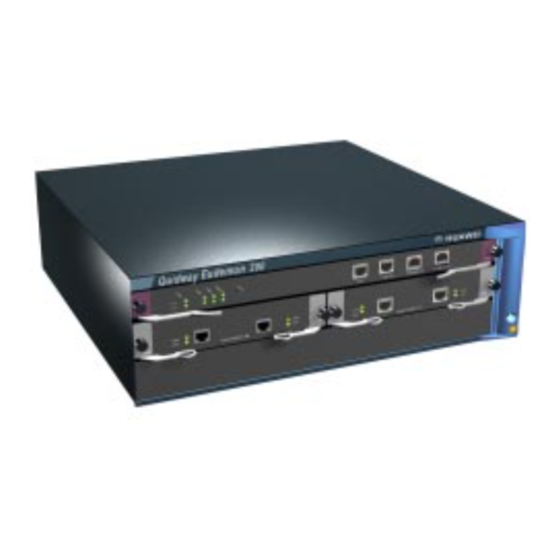
1.1 Introduction to the Eudemon200 Firewall The Eudemon200 firewall, as a new-generation high-speed firewall independently developed by Huawei, provides a cost-effective solution to small- and medium-sized Intranet network security. The chassis of the Eudemon200 firewall is equipped with console interface, AUX interface and two fixed 10/100M Ethernet interfaces. - Page 14 Installation Manual Quidway Eudemon200 Firewall Chapter 1 Overview and also supports packet filtering based on Application Specific Packet Filter (ASPF), such as channel and state inspection based on the TCP/UDP protocol, Java Blocking protection and ActiveX Blocking protection and Port-To-Application mapping. IV.
-
Page 15: Product Structure
Installation Manual Quidway Eudemon200 Firewall Chapter 1 Overview IX. Secure VPN application The Eudemon200 firewall not only supports IPSec VPN (Virtual Private Network) application that provides users with reliable transmission channel, but also it can build secure L2TP VPN, GRE VPN and L2TP over IPSec VPN. X. - Page 16 Installation Manual Quidway Eudemon200 Firewall Chapter 1 Overview 1. RPU Slot0 2. Interface Module Slot1 3. Interface Module Slot2 4. ESD-preventive wrist strap jack Figure 1-1 Front panel of the Eudemon200 firewall 1. Fan module 2. Grounding screw 3. AC power interface 4.
-
Page 17: System Parameter
Installation Manual Quidway Eudemon200 Firewall Chapter 1 Overview 1.3 System Parameters Table 1-1 System parameters of the Eudemon200 firewall Item Description Extended slot 2 10/100Mbps Ethernet ports Fixed interface 1 AUX port 1 console port PowerPC750 733MHz Boot ROM 512KB SDRAM 256MB (may be extended to 512MB) NVRAM... -
Page 18: Introduction To General Modules
Installation Manual Quidway Eudemon200 Firewall Chapter 1 Overview 1.4 Introduction to General Modules The general modules of the Eudemon200 firewall include RPU, PSU (PWR), FAN, and interface module, which will be described in the following subsections. 1.4.1 RPU I. Functions As the core component of the Eudemon200 firewall, RPU functions primarily to process protocols, forward low-speed packets, control interfaces, and detect faults. -
Page 19: Rpu
Installation Manual Quidway Eudemon200 Firewall Chapter 1 Overview II. Appearance Figure 1-3 RPU III. LED and button Table 1-2 RPU front panel, LED and button description Front panel LED and button Description System operation LED. Blinking means the CPU is in normal operation, constant ON or OFF means the CPU has failed. - Page 20 Installation Manual Quidway Eudemon200 Firewall Chapter 1 Overview Table 1-3 Console interface attributes Attribute Description Connector RJ-45 Interface standard EIA/TIA-232 Baud rate 9600bps - 115200bps 9600bps by default Connect to the ASCII terminal Connect to the serial interface of the local PC and run terminal emulation program on the Supported service Command Line Interface (CLI) AUX interface...
-
Page 21: Pwr
Installation Manual Quidway Eudemon200 Firewall Chapter 1 Overview Table 1-5 Ethernet interface attributes Attribute Description Connector RJ-45 Interface type Ethernet_II Ethernet_SNAP Supported frame format IEEE 802.2 IEEE 802.3 10M/100Mbps auto-sensing Operating mode Full duplex/Half-duplex Supported network protocol 1.4.2 PWR I. Functions The power supply system of the Eudemon200 firewall comprises two PWRs. - Page 22 Installation Manual Quidway Eudemon200 Firewall Chapter 1 Overview Note: If you want to install a Eudemon200 in a communication equipment room, you should make sure that the power distribution cabinet can provide the lightning protection box or arrester against the current of 20KA and above.
-
Page 23: Fan
Installation Manual Quidway Eudemon200 Firewall Chapter 1 Overview III. Front Panel and LED Table 1-6 PWR front panel and LED description AC Front panel DC Front panel Description ALM (red) PWR failure LED. ON means PWR is not in place or has failed. PWR operation LED. -
Page 24: Interface Module
Installation Manual Quidway Eudemon200 Firewall Chapter 1 Overview Figure 1-6 FAN 1.4.4 Interface Module 1-port 10Base-T/100Base-TX Fast Ethernet (FE) interface card (1FE) 2-port 10Base-T/100Base-TX FE interface card (2FE) 1-port 100Base-FX Ethernet multi-mode fiber interface card (1MFX) 1-port 100Base-FX Ethernet single-mode fiber interface card (1SFX) 4-port channelized T1 interface card (4T1) 4-port channelized E1 interface card (4E1) 1-port ATM 155M multi-mode fiber interface card (1ATM-OC3MM) -
Page 25: Chapter 2 Installation Preparation
Installation Manual Quidway Eudemon 200 Firewall Chapter 2 Installation Preparation Chapter 2 Installation Preparation 2.1 Site Inspection To ensure the proper working of the Eudemon200 firewall and prolong their service life, the installation site should meet the requirements described in the following subsections. -
Page 26: Electromagnetic Environment
Installation Manual Quidway Eudemon 200 Firewall Chapter 2 Installation Preparation On the communication network connected to the equipment, the static electricity is primarily introduced from the outside electrical fields, such as the outdoor high-voltage power cable and lightning, and from the inside system, such as indoor environment, floor material and the equipment frame. -
Page 27: Workbench
Installation Manual Quidway Eudemon 200 Firewall Chapter 2 Installation Preparation Add a lightning arrester for power supply onto the front end of the power input in order to protect the power supply from lightning strikes in a more effective way. - Page 28 Installation Manual Quidway Eudemon 200 Firewall Chapter 2 Installation Preparation accessories are completely consistent with the Purchase Contract. The following table lists the parts and accessories that are essential for a Eudemon 200 firewall. Table 2-2 Eudemon 200 firewall and accessories...
-
Page 29: Installation Tools, Meters And Equipment
Installation Manual Quidway Eudemon 200 Firewall Chapter 2 Installation Preparation 2.4 Installation Tools, Meters and Equipment 1. Tools ESD-preventive wrist strap Anti-static bag Phillips screwdriver P1-100MM, with the power head type D76 2x5x60. Socket M6. flat screwdriver 4-75mm. 2. Meters and equipment... -
Page 30: Chapter 3 Installation
Installation Manual Quidway Eudemon 200 Firewall Chapter 3 Installation Chapter 3 Installation 3.1 Installation Flow Start Start Mount the cabinet (optional) Mount the equipment to the specified location Connect the PGND wire Connect the power cord Connect the equipment to the console terminal... -
Page 31: Mount A Eudemon200 To A Specified Place
Chapter 3 Installation 3.2 Mount a Eudemon200 to a Specified Place The Eudemon200 firewall can be mounted in B68 cabinet provided by Huawei Technologies. For details about B68 cabinet installation, refer to “B68 Cabinet Installation”. Here, it will not be described again. -
Page 32: Mount A Eudemon200 Onto The Workbench
Installation Manual Quidway Eudemon 200 Firewall Chapter 3 Installation Fix the equipment to the rack with M3 screw through brackets. 1) Mounting screws 2) Mounting brackets (carrying cabling racks) 3) Guides Figure 3-3 Install Eudemon200 firewall into a rack 3.2.2 Mount a Eudemon200 onto the Workbench In most cases, the Eudemon200 firewall is placed on clean bench more often. -
Page 33: Connect Power Cable
Installation Manual Quidway Eudemon 200 Firewall Chapter 3 Installation against the high voltage of lightning shocks caused by external network lines like E1/T1 line and ISDN/PSTN line. The PGND screw is located at top right-rear of the chassis and identified by a grounding mark “... -
Page 34: Connect Dc-Input Power Cable
Installation Manual Quidway Eudemon 200 Firewall Chapter 3 Installation 1. Cable-retention clip 2. AC input 3. Power switch Figure 3-5 Partial appearance of AC power socket II. Recommended AC power socket The user is recommended to use a 3-line single-phase power socket with a grounding terminal, which should be reliably connected to the ground in the building. - Page 35 Installation Manual Quidway Eudemon 200 Firewall Chapter 3 Installation 1. Power switch 2. DC input Figure 3-6 Partial appearance of DC power socket II. Connect DC Power Cable Figure 3-7 DC power cable Table 3-1 DC power cable pinouts -48 power supply side...
-
Page 36: Connect The Console Terminal
Installation Manual Quidway Eudemon 200 Firewall Chapter 3 Installation Step 3: Place the power switch of the Eudemon200 firewall to the ON position. Step 4: Check that the POWER LED on the front panel of the Eudemon200 firewall is ON, which means the power cord connection is correct. -
Page 37: Connect The Eudemon200 To Lan
Installation Manual Quidway Eudemon 200 Firewall Chapter 3 Installation Step 1: Select a console terminal. Console terminal can be a standard ASCII terminal possessing an RS-232 serial port, or a regular PC, but the latter is often used. Step 2: Connect the cable. Power off the Eudemon200 firewall and console terminal, and connect the RS-232 serial port to the console port on the RPU via a console cable. -
Page 38: Connect The Eudemon200 To Wan
Installation Manual Quidway Eudemon 200 Firewall Chapter 3 Installation Note: The standard equipping package of the Eudemon200 firewall has included the interface cables for the fixed Ethernet ports. When preparing network cables, please use shielded twisted-pair (STP) cables so long they are available for the sake of electromagnetic compatibility. - Page 39 Installation Manual Quidway Eudemon 200 Firewall Chapter 3 Installation I. Introduction to AUX interface AUX is an EIA/TIA-232-compliant asynchronous serial interface that can provide backup for a WAN interface. Usually, it functions to provide dial connection. In case of console failure, AUX can function as a console interface. For the AUX interface attributes, refer to the section 1.4.
-
Page 40: Verify Installation
Installation Manual Quidway Eudemon 200 Firewall Chapter 3 Installation 3.8 Verify Installation During equipment installation, you must verify the installation each time you power on the Eudemon200 firewall, making sure that Enough clearance has reserved around the Eudemon200 firewall for adequate dissipation and the cabinet is stable enough. -
Page 41: Chapter 4 Boot And Configuration
Installation Manual Quidway Eudemon 200 Firewall Chapter 4 Boot and Configuration Chapter 4 Boot and Configuration 4.1 Boot the Eudemon200 4.1.1 Establish Configuration Environment I. Connect the Eudemon200 to a configuration terminal To set up the local configuration environment, RJ-45 connector of the console cable needs to be connected to the console port on the Eudemon200 firewall, and DB-25 connector or DB-9 connector to the serial interface of a PC, as shown in Figure 4-1. - Page 42 Installation Manual Quidway Eudemon 200 Firewall Chapter 4 Boot and Configuration Figure 4-2 New connection Step 2: Set terminal parameters Parameters of the HyperTerminal of Windows98 are set as follows: Select a connection port: While implementing the local configuration, choose the serial interface to be connected in the Connect Using box, as shown in Figure 4-3.
- Page 43 Installation Manual Quidway Eudemon 200 Firewall Chapter 4 Boot and Configuration Baud rate 9600, Data bits 8, Parity None, Stop bits 1, and Flow control None. Click the <OK> button to return to the HyperTerminal interface. Figure 4-4 Setting serial interface parameters Set HyperTerminal properties.
-
Page 44: Power On The Eudemon200
Installation Manual Quidway Eudemon 200 Firewall Chapter 4 Boot and Configuration Figure 4-5 Setting terminal type 4.1.2 Power on the Eudemon200 I. Check before power-on Perform the following check items before powering on a Eudemon200 firewall: Whether the power cord and ground wire are correctly connected. -
Page 45: Startup Process
Installation Manual Quidway Eudemon 200 Firewall Chapter 4 Boot and Configuration II. Power on the Eudemon200 Turn on the power switch of the Eudemon200 firewall. III. Check/Operate after power-on After powering on the Eudemon200 firewall, check Whether the LEDs on the front panel are normal. - Page 46 And then, the following information displays on the screen: ******************************************************* Firewall Platform 8060 Bootrom, Ver 1.08 *← BootROM version ******************************************************* Copyright(C) 2001-2005 by HUAWEI TECHNOLOGIES CO.,LTD. Creation date: Nov 10 2003, 13:15:42 CPU type : IBM750FX CPU L2 Cache : 512KB...
-
Page 47: Configuration Fundamentals
Installation Manual Quidway Eudemon 200 Firewall Chapter 4 Boot and Configuration IV. Decompress Application If the application files read into the SDRAM pass the checking, they will be decompressed. And the terminal screen displays the following information: Begin Decompressing .......... -
Page 48: Command Line Interface
Step 7: If there is any special reliability requirement, perform the reliability configuration for the Eudemon200 firewall. Refer to Quidway Eudemon 200 Firewall Operation Manual for detailed introduction of the protocols or function configuration the Eudemon200. 4.2.2 Command Line Interface I. -
Page 49: Slot Arrangement And Interface Numbering Rules
Ethernet port number of 2FE module is Ethernet 2/0/0 and Ethernet 2/0/1. Every interface is configured in special view. For details, refer to Operation Manual. 4.3 Software Maintenance Huawei independently develops the Eudemon200 software according to users’ requirements. For details about the basic software realization from the point of ordinary... - Page 50 Installation Manual Quidway Eudemon 200 Firewall Chapter 4 Boot and Configuration operation, which includes the first time start, the upload, download and software upgrading of the Eudemon200, refer to Operation Manual. Caution: Do not upgrade the Eudemon200 firewall software at will. If the upgrade is necessary, it is recommended to perform it under the guidance of the technical support personnel.
-
Page 51: Chapter 5 Hardware Maintenance
Replace the hardware of Eudemon200 sensibly and in a proper way under the guidance of the technical support personnel. Remember to wear ESD-preventive wrist strap and make it well contact with your skin. For the device to operate normally, use the SDRAM provided by Huawei Technologies Co, Ltd. only. 5.1 Tools Required Phillips screwdriver P1-100MM... -
Page 52: Install A Power Module
Installation Manual Chapter 5 Hardware MaintenanceHardware Quidway Eudemon 200 Firewall Maintenance Caution: If no power module has been installed in the slot, install the blank filler panel to keep air going and heat dissipation and prevent dust entering. Figure 5-1 Power module removal 5.2.2 Install a Power Module... -
Page 53: Install A Fan
Installation Manual Chapter 5 Hardware MaintenanceHardware Quidway Eudemon 200 Firewall Maintenance Step 1: Loosen the two captive screws of a fan. Step 2: One hand holds the handle attached to the front of the fan and pull part of it out, while the other hand holds the bottom of the fan. -
Page 54: Rpu Removal And Installation
Installation Manual Chapter 5 Hardware MaintenanceHardware Quidway Eudemon 200 Firewall Maintenance 5.4 RPU Removal and Installation 5.4.1 Remove an RPU Step 1: Power off the switch. (If there are two power modules installed, turn both of them off). Step 2: Loosen the captive screws at both sides of the RPU. - Page 55 Installation Manual Chapter 5 Hardware MaintenanceHardware Quidway Eudemon 200 Firewall Maintenance Start Start Prepare tools Prepare tools Remove the RPU Remove the RPU Locate the SDRAM Locate the SDRAM on the RPU on the RPU Remove the SDRAM Remove the SDRAM...
- Page 56 Installation Manual Chapter 5 Hardware MaintenanceHardware Quidway Eudemon 200 Firewall Maintenance II. Remove the SDRAM Step 1: Press outward, the locking clips at both sides of the SDRAM slot with an appropriate force, and the SDRAM will spring out from the slot.
-
Page 57: Chapter 6 Troubleshooting
Installation Manual Quidway Eudemon 200 Firewall Chapter 6 Troubleshooting Chapter 6 Troubleshooting 6.1 Troubleshooting of the Power System Fault POWER LED run is OFF or blinks. Troubleshooting Check: Whether the power switch of the Eudemon200 is turned on. Whether the power supply switch is turned on. -
Page 58: Troubleshooting Of Application Software Upgrade
Installation Manual Quidway Eudemon 200 Firewall Chapter 6 Troubleshooting Whether the power system is normal. Whether the console cable is connected correctly. Step 2: In case of not finding any problem after having checked the items above, it is likely that there is something wrong with the console cable or the terminal (e.g., the HyperTerminal) parameters. - Page 59 Installation Manual Quidway Eudemon 200 Firewall Chapter 6 Troubleshooting Loading... Loading Failed Troubleshooting The fault occurs due to downloading the device “ErrDev” using a wrong application. To solve the problem, just change “ErrDev” to “wancom” which is the application upgrade device of Eudemon200.
- Page 60 Installation Manual Quidway Eudemon 200 Firewall Chapter 6 Troubleshooting DownLoad Program To Flash Through Net Port boot device : wancom unit number processor number file name : e200.bin inet on ethernet (e) : 1.1.1.1 host inet (h) : 1.1.1.2 user (u)
-
Page 61: Chapter 7 Interface Module
Installation Manual Quidway Eudemon 200 Firewall Chapter 7 Interface Module Chapter 7 Interface Module 7.1 Interface Module Category Table 7-1 shows interface modules supported by the Eudemon200 firewall. Table 7-1 Interface module name abbreviation table Interface module Order type Full name... -
Page 62: Troubleshooting
Installation Manual Quidway Eudemon 200 Firewall Chapter 7 Interface Module Caution: The shielding fingers on the front panel of interface module achieve special electromagnetic shielding effect for the whole Eudemon200 firewall. Please ensure their integrity when uninstalling or replacing an interface module and never damage them. -
Page 63: 1Fe/2Fe
Installation Manual Quidway Eudemon 200 Firewall Chapter 7 Interface Module In the event that an interface module is not working normally, locate the problem by performing the following operations. Check the interface cables, making sure that you have used the correct cables. -
Page 64: Panel And Interface Led
Installation Manual Quidway Eudemon 200 Firewall Chapter 7 Interface Module 7.4.3 Panel and Interface LED Table 7-3 1FE/2FE panels and LEDs description Name Panel figure Category Flash state and description LINK OFF means the link is not connected and ON means the link is connected. -
Page 65: Connect Interface Cable
Installation Manual Quidway Eudemon 200 Firewall Chapter 7 Interface Module Crossover cable: The wire sequences of the twisted pairs crimped in the RJ-45 connectors at both ends are different. It is used for connecting two terminal devices (e.g., PC and router). Users can make it as needed. -
Page 66: Interface Attributes
Installation Manual Quidway Eudemon 200 Firewall Chapter 7 Interface Module Note: In terms of transmission mode, optical fibers fall into multi-mode optical fiber and single-mode optical fiber. Single-mode optical fiber has very thin core, and transmits only in single mode on a given wavelength. -
Page 67: Panel And Interface Led
Installation Manual Quidway Eudemon 200 Firewall Chapter 7 Interface Module 7.5.3 Panel and Interface LED Table 7-5 1MFX/1SFX panels and LEDs description Name Panel figure 1MFX 1SFX Category Flash state and description LINK OFF means the link is not connected and ON means the link is connected. -
Page 68: Connect Interface Optical Fiber
Installation Manual Quidway Eudemon 200 Firewall Chapter 7 Interface Module Note: Optical fiber connector is defined by ITU recommendations as the passive component used to stably but not permanently connect two or more optical fibers. Optical fiber connectors are the passive components indispensable to the optical fiber communications system in the sense that they make it possible to perform the pluggable connections between optical channels. -
Page 69: 4E1
Installation Manual Quidway Eudemon 200 Firewall Chapter 7 Interface Module optical port of the peer device; insert one end of another optical fiber into the Tx optical port of 1MFX/1SFX, and the other end into the Rx optical port of the peer device. -
Page 70: Panel And Interface Led
Installation Manual Quidway Eudemon 200 Firewall Chapter 7 Interface Module Description Attribute protocol 7.6.3 Panel and Interface LED Table 7-7 illustrates the 4E1 panels and LEDs description. Table 7-7 4E1 panels and LEDs description Name Panel figure Category Flash state and description LINK OFF means the link is not connected and ON means the link is connected. - Page 71 Installation Manual Quidway Eudemon 200 Firewall Chapter 7 Interface Module DB25 male DB15 female Figure 7-3 120-ohm 4E1 adapter cable Figure 7-4 75-ohm 4E1 adapter cable 7-11...
-
Page 72: Internal Dip Switch
Installation Manual Quidway Eudemon 200 Firewall Chapter 7 Interface Module Note: Both 75-ohm 4E1 adapter cable and 120-ohm 4E1 adapter cable are required for 4E1, but E1 cable is optional, so you need to order the E1 cable when purchasing a 4E1. Otherwise, it will not be provided. -
Page 73: Connect Interface Cable
Installation Manual Quidway Eudemon 200 Firewall Chapter 7 Interface Module Table 7-9 Description and setting of the DIP switches of 1 4E1 Configuration of Configuration of 120-ohm DIP switch Description 75-ohm impedance impedance 1BIT 2BIT 75-ohm/120-ohm 3BIT selection switch 4BIT... -
Page 74: 4T1
Installation Manual Quidway Eudemon 200 Firewall Chapter 7 Interface Module Caution: You must connect a cable to the interface with the appropriate mark. Misplugging is prone to impair the interface module and even damage the interface module mainframe. When the interface cables of 4E1 are led to the outdoors, you are recommended to install a special lightning arrester at the input end of the telephone line for the purpose of achieving a better lightning protection effect. -
Page 75: Panel And Interface Led
Installation Manual Quidway Eudemon 200 Firewall Chapter 7 Interface Module Table 7-10 Interface attributes of 4T1 Attribute Description Connector RJ-45 Connector number Interface standard G.703/T1 102, G.704 Interface speed 1.544Mbps Cable T1 cable (100-ohm standard shielded cable) Operating mode FT1, CT1, PRI... -
Page 76: Connect Interface Cable
Installation Manual Quidway Eudemon 200 Firewall Chapter 7 Interface Module Figure 7-6 T1 cable In addition, you may choose to extend the T1 cable by using a network interface connector that has an RJ-45 receptacle at each end. Note: Both T1 cable and network interface connector are optional accessories. You should order them together with the 4T1. -
Page 77: 1Atm-Oc3Mm/1Atm-Oc3Sm/1Atm-Oc3Sml
Installation Manual Quidway Eudemon 200 Firewall Chapter 7 Interface Module T1 cable (100-ohm straight-through shielding network cable) Network interface connector RJ45 Eudemon DDN, etc RJ45 Straight-through network cable RJ45 Figure 7-7 Extend the T1 cable Step 3: Power on the Eudemon200, and check the status of the LINK LED on the module panel. -
Page 78: Interface Attributes
Installation Manual Quidway Eudemon 200 Firewall Chapter 7 Interface Module 7.8.2 Interface Attributes Table 7-12 Interface attributes of the ATM modules Attribute 1ATM-OC3MM 1ATM-OC3SM 1ATM-OC3SML Optical fiber connector Connector number Interface standard SONET OC-3/SDH STM-1 Interface speed 155Mbps Cable and the... -
Page 79: Interface Optical Fiber
Installation Manual Quidway Eudemon 200 Firewall Chapter 7 Interface Module Table 7-13 1ATM-OC3MM/1ATM-OC3SM/1ATM-OC3SML panels and LEDs description Name Panel figure 1ATM-OC 1ATM-OC 1ATM-OC 3SML Category Flash state and description LINK OFF means the link is not connected and ON means the link is connected. -
Page 80: Connecting Interface Optical Fiber
Installation Manual Quidway Eudemon 200 Firewall Chapter 7 Interface Module Note: 1. Optical fiber connectors (Live tie-in is the common name): ITU recommends to define it as “Used to connect passive components of two or several optical fibers steadily but not permanently”. Optical fiber connectors are indispensable passive components in optical fiber communication system. - Page 81 Installation Manual Quidway Eudemon 200 Firewall Chapter 7 Interface Module Note: 1ATM-OC3SML adopts long-distance fiber interface, requiring a transmission at least longer than 25km. If the transmission distance is lower than 25km, the interface will be unable to receive signals.
-
Page 82: Appendix A Specifications Of Interface Cables
Installation Manual Quidway Eudemon 200 Firewall Appendix A Specifications of Interface Cables Appendix A Specifications of Interface Cables Note: The pinouts not described in the following tables of this appendix are not connected. A.1 Console Cable Table A-1 Console cable pinouts... -
Page 83: Ethernet Cable Pinouts
Installation Manual Quidway Eudemon 200 Firewall Appendix A Specifications of Interface Cables Signal RJ45 DB25 Signal Direction A.3 Ethernet Cable Pinouts A.3.1 RJ45 Connector PIN #8 PIN #1 Figure A-1 RJ45 connector A.3.2 Category 5 Twisted Pair Category 5 twisted pair comprises 8-core copper wires. -
Page 84: Ethernet Cable Pinouts
Installation Manual Quidway Eudemon 200 Firewall Appendix A Specifications of Interface Cables Blue Pair 1 White/Blue Orange Pair 2 White/Orange Green Pair 3 White/Green Brown Pair 4 White/Brown Figure A-2 Category 5 twisted pair A.3.3 Ethernet Cable Pinouts Table A-3 Straight -through cable pinouts... -
Page 85: E1 Cable And 4E1 Conversion Cable
Installation Manual Quidway Eudemon 200 Firewall Appendix A Specifications of Interface Cables Signal Category 5 RJ45 Signal Direction RJ45 Direction Twisted Pair White (Brown) Brown Note: The above table can be used as reference while distinguishing or preparing the two kinds of Ethernet cables. - Page 86 Installation Manual Quidway Eudemon 200 Firewall Appendix A Specifications of Interface Cables Table A-6 4E1 conversion cable pinouts DB25 DB15 Serial number Pinout Pinout Signal Signal TxR4 TxRing RxSD4 RxShield RxT4 RxTip TxT4 TxTip TxSD4 TxShield RxR4 RxRing TxR3 TxRing...
-
Page 87: T1 Cable
Installation Manual Quidway Eudemon 200 Firewall Appendix A Specifications of Interface Cables A.5 T1 Cable Table A-7 T1 cable pinouts Straight-through RJ45 Shielded Network Signal Description RJ45 Cable White (Orange) Ring Orange White (Green) Blue Ring White (Blue) Green White (Brown)